
 There are some great libraries that make it really easy to use the pins on the Raspberry Pi. It has relatively few pins and are a little less powerful than what you might expect from a microcontroller. Aside from those limitations, you should also keep in mind that pin manipulation is not done in a real time environment. Unlike an Arduino, which only runs your program, the Raspberry Pi takes turns running many programs like a normal desktop. While your program might be able to recieve the majority of the processor's attention, it will not be able to use all of it. Likewise, timing events may be slightly less reliable too. As great as Python is, it is even less reliable because of a process called garbage collection. It is not a problem for most situations, but it is definitely something to keep in mind.
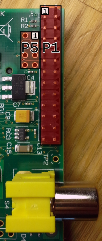
There are two kinds of numbers to specify which pin you want to use. There is the physical pin number, which altenate sideways increasing from top to bottom. For nearly any device, if you look carefully on the board, there is an indicator near the "1" pin on a header. This is even true of integrated circuit (IC) chips. Unlike with ICs, orienting the pins with that indicator in the top left, the pin numbers are increased from left to right and top to bottom. The reason this appears differently on P5 is because the indicator is on the bottom side.
The BCM GPIO number is the number that the processor uses to differentiate the pins. Obviously, pins like 5V and GND cannot be addressed since they only have their one purpose and cannot be changed. As a result, the BCM number is different than the header number. It is important to keep track of which addressing system you are using. It might help you to remember that BCM is a reference to the signal name on the Broadcom datasheet for the processor on the Raspberry Pi.
You should also know that the pinout information only pertains to the revision 2 version of the board. You can tell that you are not using a revision 1 board by the presense fo the P5 holes. P5 was added in revision 2. Revision 1 is essentially the same, but has quite a few pins missing.
| BCM GPIO# | Name | Header | Name | BCM GPIO# | |
|---|---|---|---|---|---|
| 3.3V | 2 | 1 | 5V | ||
| 29 | GPIO9 | 4 | 3 | GPIO8 | 28 |
| 31 | GPIO11 | 6 | 5 | GPIO10 | 20 |
| GND | 8 | 7 | GND | ||
| BCM GPIO# | Name | Header | Name | BCM GPIO# | |
|---|---|---|---|---|---|
| 3.3V | 1 | 2 | 5V | ||
| 2 | SDA* | 3 | 4 | 5V | |
| 3 | SCL* | 5 | 6 | GND | |
| 4 | GPIO7 | 7 | 8 | TX | 14 |
| GND | 9 | 10 | RX | 15 | |
| 17 | GPIO0 | 11 | 12 | PWM0 | 18 |
| 27 | GPIO2 | 13 | 14 | GND | |
| 22 | GPIO3 | 15 | 16 | GPIO4 | 23 |
| 3.3V | 17 | 18 | GPIO5 | 24 | |
| 10 | SPI MOSI | 19 | 20 | GND | |
| 9 | SPI MISO | 21 | 22 | GPIO6 | 25 |
| 11 | SPI SCLK | 23 | 24 | SPI CE0 | 8 |
| GND | 25 | 26 | SPI CE1 | 7 | |
*The i2c pins conveniently have 1.8 kΩ pullup resistors.
Each of these pins have their own limitations:
| Pin Type | Max Current |
|---|---|
| 3.3V | 50mA |
| 5V | 200mA |
| GPIO | 16mA @ 3.3V |
| Total GPIO | 51mA |
| Input High | >1.3V |
| Input Low | <0.8V |
It might be possible that the "total GPIO" and "3.3V" limitations both refer to the same number. Needless to say, in any case you really cannot put much on the GPIO or 3.3V power. Really, it's just two LEDs and you're already at 40-60mA.
Given the voltage and current limits of these pins, you will likely find yourself needing ways around them. A logic level converter is good for interfacing 3.3V serial and GPIO to 5V devices. Shift registers and I/O port expanders are both good for both being able to deliver more current and adding more pins. There are all sorts of ways around these limitations, but simple stuff like MOSFETS, transistors, and voltage regulators can be the most effective. There are also no analog inputs, so to read voltage you can use an Analog to Digital Converter (ADC). One way to get around all of these limitations is to use an ATmega or Arduino for any controls, and just use the Raspberry Pi for anything resource intensive, but interfacing the two still requires a logic level converter since they usually operate at different voltages. There are 3.3V Arduino variants though.
Using the GPIO Pins
GPIO is easily done with the rpi-gpio python package. First, make sure you have it installed by opening a terminal (like LXterminal)
sudo apt-get update
sudo apt-get install python-dev python-rpi.gpio
Then, just make a plain text file using whatever editor you like containing something like this:
import RPi.GPIO as io
import time

io.setmode(io.BCM)
# io.BCM says use the BCM GPIO numbering system for pins.
# io.BOARD will use the actual "header" numbers.

# reading from a GPIO pin
inputPinNumber = 18                     # the BCM GPIO pin number, 12 if io.BOARD
io.setup(inputPinNumber, io.IN)         # similar to pinMode in Arduino
if io.input(inputPinNumber):            # read the pin, use in if condition
    print("Pin 18 is high")
else:
    print("Pin 18 is low")

# writting to a GPIO pin
outputPinNumber = 23                    # the BCM GPIO pin number, 16 if io.BOARD
io.setup(outputPinNumber, io.OUT)
while True:                             # loop forever
    io.output(outputPinNumber, io.HIGH) # set the pin output to high (3.3V)
    time.sleep(0.5)                     # wait a half a second
    io.output(outputPinNumber, io.LOW)  # set the pin output to low (0V)
    time.sleep(0.5)                     # wait another half a second before looping
You will need to run it as root, since GPIO manipulation requires root priviliges.
pi@raspberrypi ~ $ sudo python pinIOtest.py
Using i2C and SPI
These serial connections require a little more setup because they require kernel modules, which are like drivers. They disabled them by default because "many users don't need them". I guess we are one of the few, huh?
You can copy these lines to a terminal like LXterminal or in SSH. The stuff after the # is just comments to explain what they do. You don't need to retype it, but it won't hurt if you're copy and pasting either.
sudo rm /etc/modprobe.d/raspi-blacklist.conf # remove their "disable"
sudo modprobe i2c-bcm2708 i2c-dev            # enable modules now without restart
echo i2c-bcm2708 | sudo tee /etc/modules     # add the i2c driver to startup
echo i2c-dev | sudo tee /etc/modules         # add other i2c driver to startup
sudo apt-get install python-smbus i2c-tools  # install some useful i2c tools
Now you can see what's connected to i2c with this neat command:
pi@raspberrypi ~ $ sudo i2cdetect -y 1
     0  1  2  3  4  5  6  7  8  9  a  b  c  d  e  f
00:          -- -- -- -- -- -- -- -- -- -- -- -- --
10: -- -- -- -- -- -- -- -- -- -- -- -- -- -- -- --
20: 20 -- -- -- -- -- -- -- -- -- -- -- -- -- -- --
30: -- -- -- -- -- -- -- -- -- -- -- -- -- -- -- --
40: -- -- -- -- -- -- -- -- -- -- -- -- -- -- -- --
50: -- -- -- -- -- -- -- -- -- -- -- -- -- -- -- --
60: -- -- -- -- -- -- -- -- -- -- -- -- -- -- -- --
70: -- -- -- -- -- -- -- --
The output shows that there is a device connected to the i2c bus and has an address of 20. This is the default address for an MCP230 port expander, which is what I have hooked up to it. If nothing were hooked up to the SCL and SDA that was i2c compatible, there would be "--" there, just like everything else.
Now, to use i2c in a Python program, use the SMBus package:
import smbus
bus = smbus.SMBus(1)
address = 0x20
write_byte(addr,val)
read_byte(addr)