Introduction
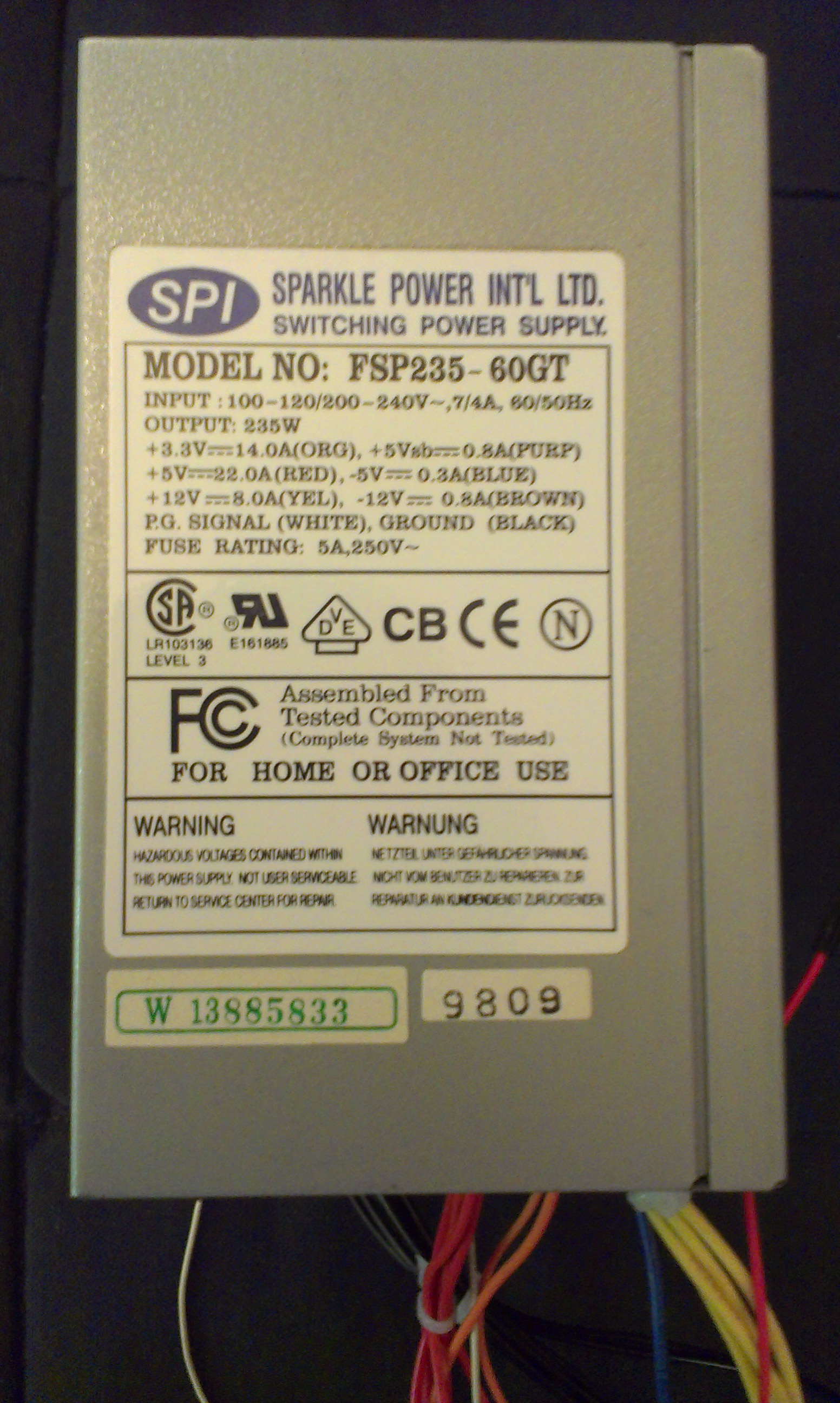
A lot of us have an old desktop computer we don't want anymore and it's good to re-use components. You'll find in each standard sized desktop, an ATX power supply. It's a standardized form factor for AC-to-DC power conversion with +3, +5, +12, and sometimes -5 and -12 VDC rails. If you look on the side, there is a sticker that will say what power it is rated to output.
Most power supplies are rated for usage in the range of 300 Watts to 600 Watts. High end ones go from 700 to 1200 Watts. That's not "toy" power. It can be dangerous and these things don't seem to have any fuses or anything in them. I melted a +5VDC wire for a few seconds when it accidentally contacted a ground. You could definitely start a fire with this and maybe hurt yourself. That being said, it is nice to have a nearly unlimited and somewhat well regulated power supply for no cost. You can get them new for about 20$ too, which seems like a good deal due to the variety of standardized voltages available.
It is not entirely straightforward to use these. They don't just turn on when they get power and there is no button for it. It is designed to be managed by an ATX compatible motherboard on computer. Basically, you need to short a specific pin to ground with a specific resistance (or use a potentiometer, like I did).
Completed Project Gallery:
Parts
- A computer (ATX) power supply
- A potentiometer OR an appropriate resistor and toggle button
- A green LED for the power indicator
- A red LED to show that the supply is on
- Two resistors (220-1000 Ohm) for the LEDs
- Binding Posts (optional)
- Voltage Regulators (optional)
Planning
If you want to add a button or potentiometer to turn it on, you'll need to cut a hole for it in the back. Potentiometers and certain buttons work nice because all you need to do is drill a hole of the right size and you can easily attach it with a nut and lock washer.
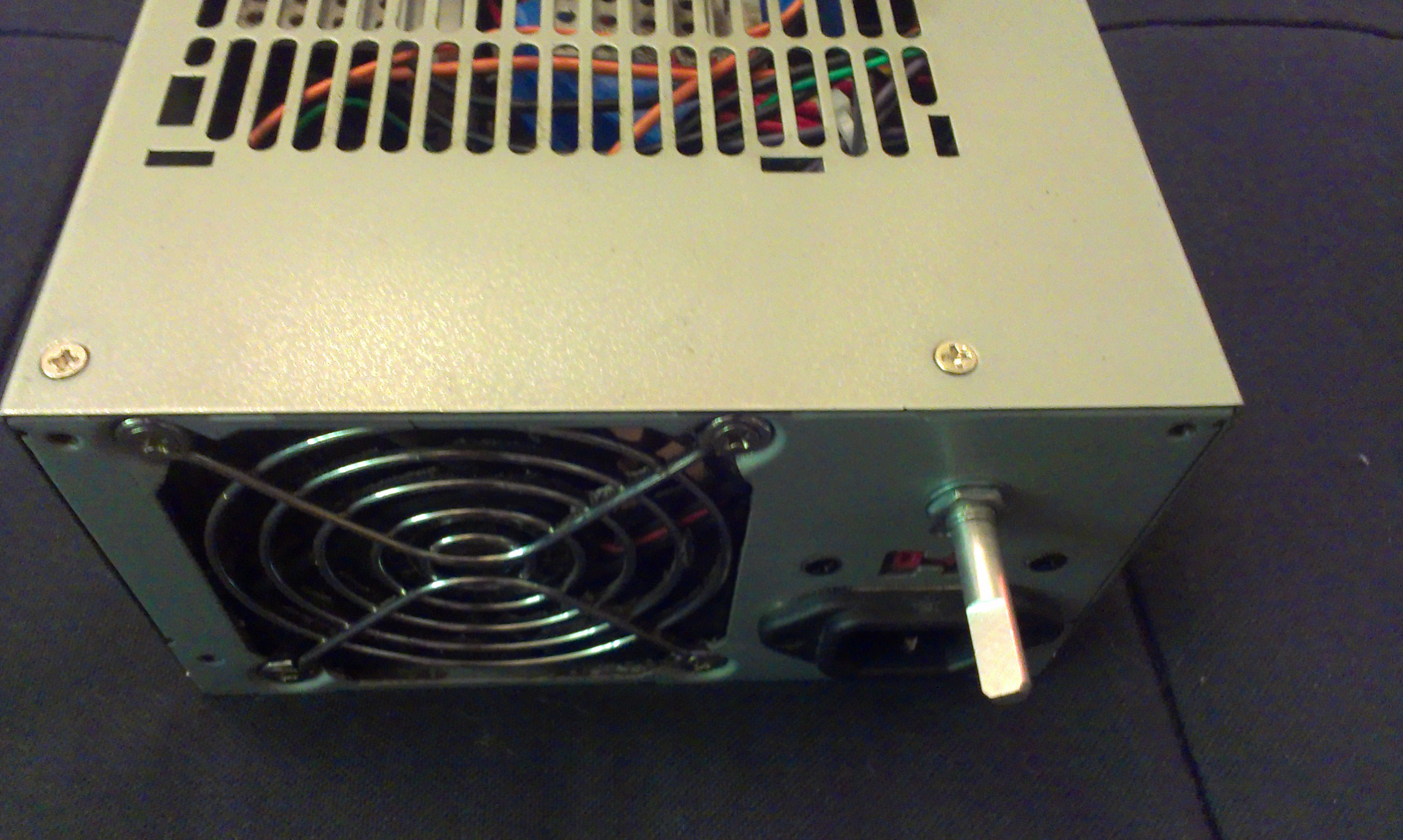
If you want some indicator LEDs, you'll have to drill holes for those too - probably on the front somewhere. You will need to open up the power supply and look carefully for a place to drill that won't damage the components.
Wiring
The Standard Connectors
| Color | Signal | Pin | Pin | Signal | Color |
|---|---|---|---|---|---|
| Orange | +3.3 V | 1 | 13 | +3.3 V | Orange |
| sense | Brown | ||||
| Orange | +3.3 V | 2 | 14 | −12 V | Blue |
| Black | Ground | 3 | 15 | Ground | Black |
| Red | +5 V | 4 | 16 | Power on | Green |
| Black | Ground | 5 | 17 | Ground | Black |
| Red | +5 V | 6 | 18 | Ground | Black |
| Black | Ground | 7 | 19 | Ground | Black |
| Grey | Power good | 8 | 20 | Reserved | N/C |
| Purple | +5 V standby | 9 | 21 | +5 V | Red |
| Yellow | +12 V | 10 | 22 | +5 V | Red |
The standard connectors, ATX and Molex, will both be removed and reorganized into something more like a lab power supply than one that can only power a desktop computer.
The ATX connector has 20 pins and a clip on one side: 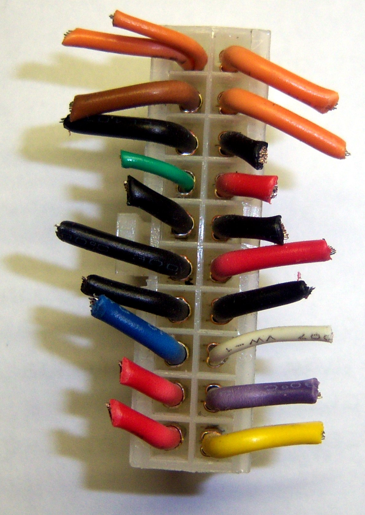
Note that the pins in the photo are flipped horizontally from the pins according to wikipedia. Also, some of those pins don't match up. The colors seem to be accurate though. You may wish to look for a version of the ATX table that matches the configuration of your power supply.
If you have that smaller orange/brown wire on Pin 13, just cut it off completely. It is not very useful and just confuses things. On mine, it was orange, so I kept thinking it was supposed to be 3.3V.
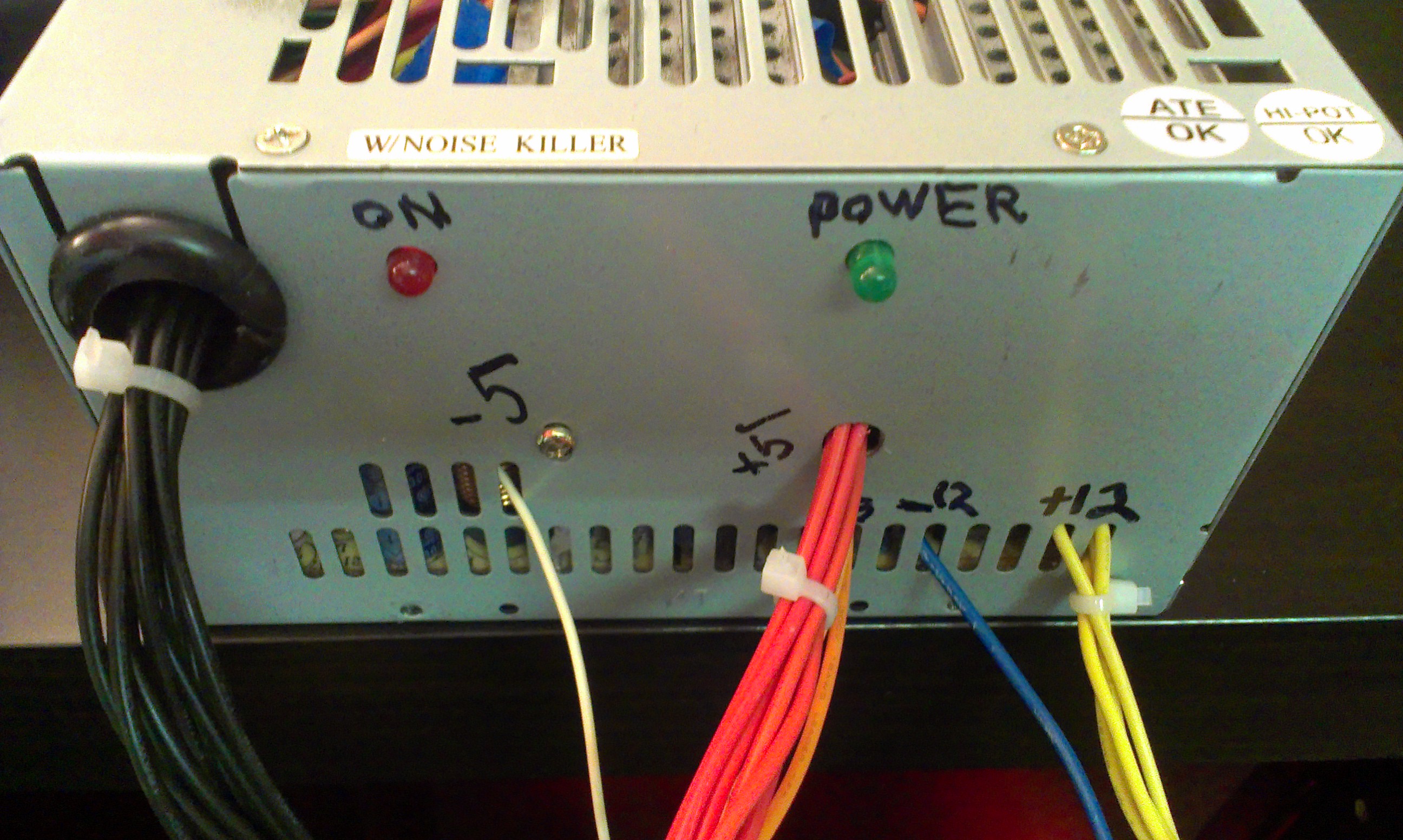
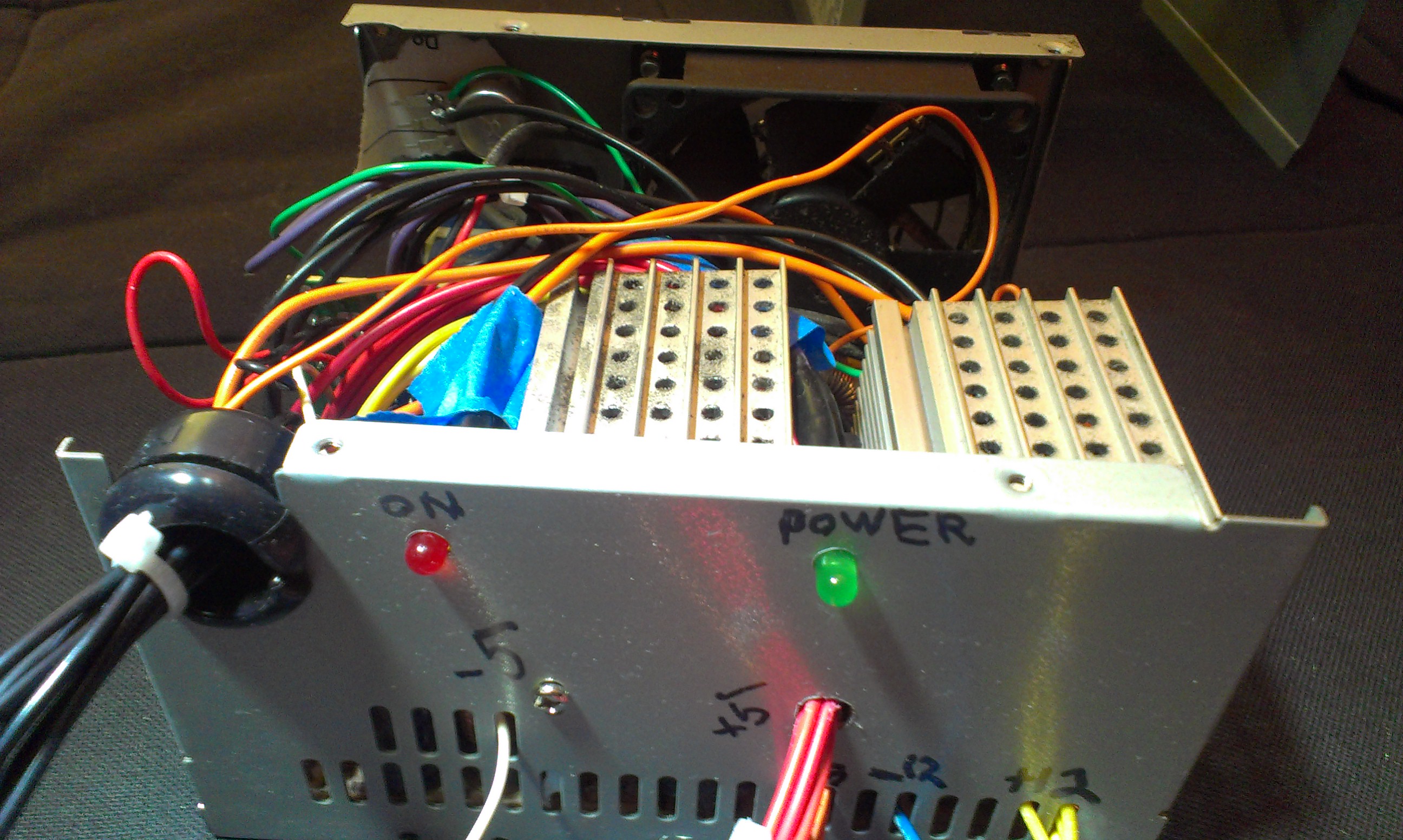
The ON Switch
Turning the power supply on isn't entirely straightforward. It won't just turn on when you plug it in.
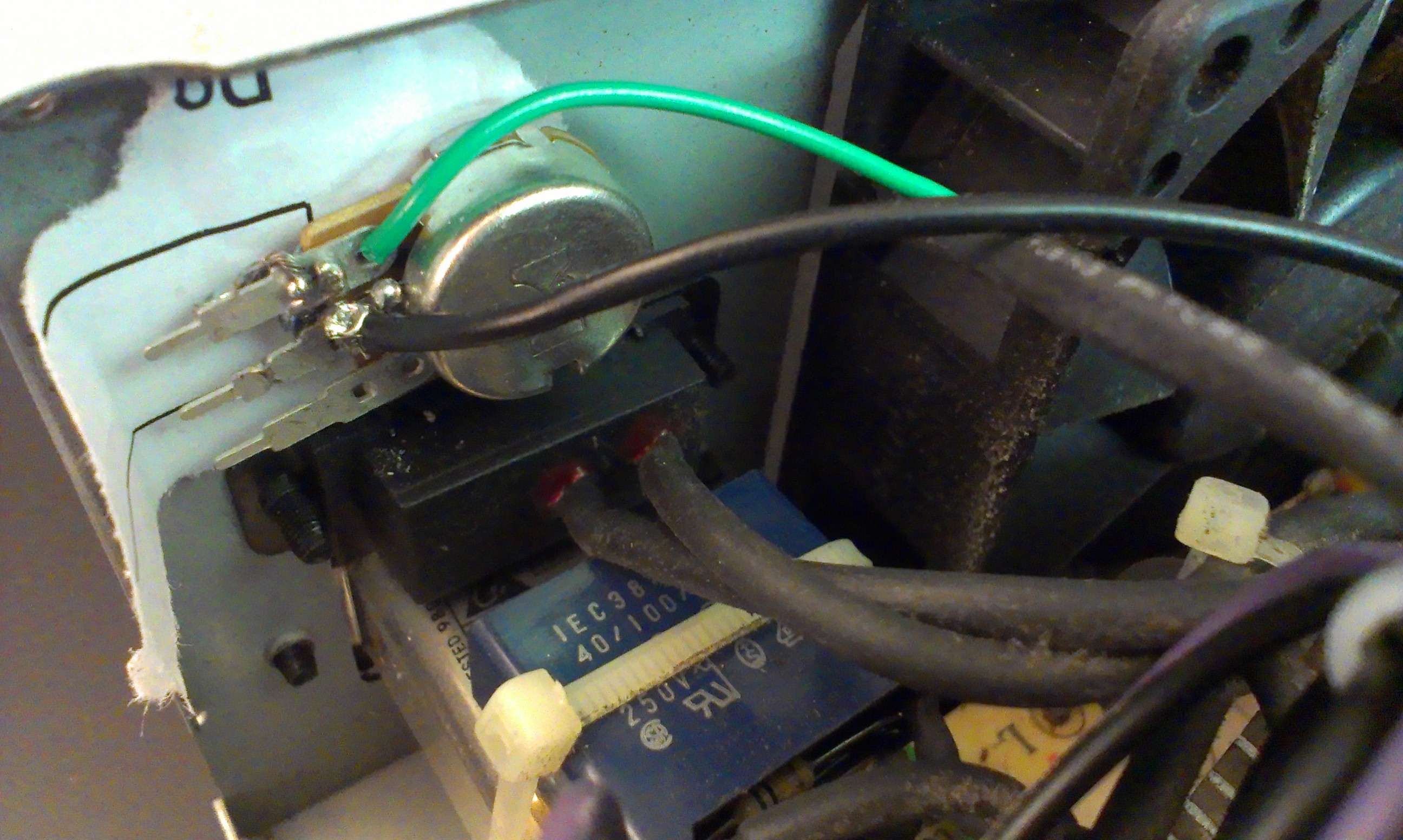
You can touch the green wire, which is the "Power On" (aka PS_ON) to a Ground (black wire). However, it needs a specific resistance. Otherwise it will just turn on for a fraction of a second and then turn back off. Rather than just trying out what resistance it needed, I used a potentiometer. If you want to use a button, I'd still use the potentiometer to experimentally determine the range of values you can use for the resistance.
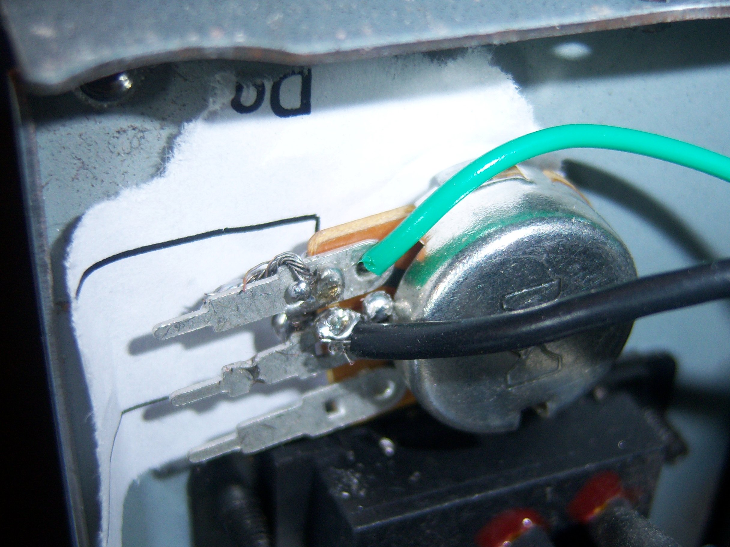
Be very sure when testing how to turn it on that you don't shock yourself, or have any of the leads touching each other. At this point, you should only really need to have cut the green wire out of the 20 pin ATX molex connector and any of the black grounds.
Clearly, I did not do a great job of soldering this thing. It was actually my first time ever soldering, and it works. Minor victory.
The green wire can go on either end of the potentiometer (pot) - all it will change is which end has higher resisistance. The ground goes on the middle pin. I would guess you could probably even flip these wires and it would still work.
If you want to use a button, try turning on the power supply with the potentiometer a few times. Get a multimeter / voltmeter and see what the resistance is of the potentiometer between the two pins you are using. That will be the resistance you should target between your button.
Power LEDs
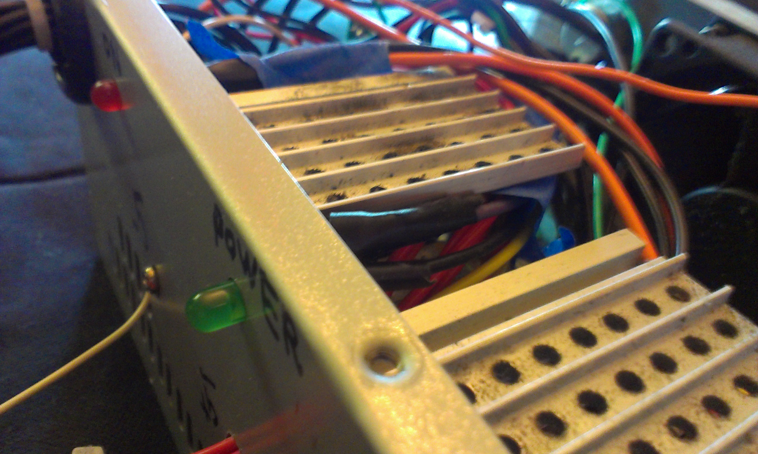 If you want an LED to be on whenever the powersupply has power - even if the power supply isn't on - you can use the purple wire, which is labelled as the +5V standby pin. So, just connect an LED+resistor combination that can deal with a 5VDC connection.
To mount the LED, I did not use any sort of clips or brackets. I just drilled a hole and taped the wires so the LED should stay in place. It isn't fool proof or professional looking, but it gets the job done.
Organizing Leads
This is the most creative part of the project. You can drill holes, use the existing hole, or try to wedge them through the grill of the plate. I opted to try them all. I wanted to have the most seperation between each of the different types of leads. This allowed me to also label them.
There are definitely some much more elegant solutions to this, such as using banana / twist mounts ( binding posts ) instead of exposing the wires. The case could also be removed altogether and simply put the power supply directly into your project's chasis.