Introduction
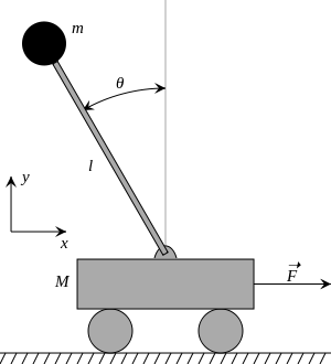
Balancing an inverted pendulum is the typical example when demonstrating a control system. A weight on an arm above the rotation pivot is an unstable system. It has one stable point when the weight is perfectly balanced. If the weight is slightly on either side of this point it will begin to move away from this stable point. On the other hand, a weight on an arm below the rotation pivot is a stable system. The weight is stable at the point exaclty below the pivot as well, but if it is moved slightly away from this point it will move back towards it.
I have built a simulation using web standards like JavaScript and HTML so you can observe the impact different PID controls have on an inverted pendulum. You can modify the gains of the proportional, integral, and derivative controls to test how each component works. The simulation is optimized to be used with Chrome and Firefox, but has a limited set of features available for Internet Explorer.
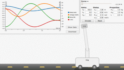
A screenshot of the simulation. Click to do your own simulations.
The simulation physics are done using techniques taught in Dr Brianno Coller's Computational Methods course including RK4 integration.
Simulation Usage
The simulation is designed to be very easy to use. Here are some steps to run your own test.
- Modify the control gains, initial states, and properties of the system
- Click "simulate".
- Observe the behavior of the system. In particular, watch the direction the forces are being applied by the controller, and how well the weight is being balanced.
- When done, click "stop". The simulation can be run for several minutes - much longer and it may become unresponsive due to the accumulation of many data points.
- A graph will appear. You can show and hide variables by clicking on them in the legend. You can also download the data in CSV format by clicking the "download" button. If using Internet Explorer, the "show" button must be used, and data can be copied manually.
- Click "reset". Repeat (go to step 1).
Dynamics
The true diferential equations for the motion of the system can be found on Wikipedia.
![]()
![]()
In some derivations, the centripital acceleration force due to the angular velocity is left out. The dynamics in this simulation does not rule out this term. However, it may be safe to neglect the term when designing the control system due to the fact that a balanced pendulum should have low velocity.
To simulate these dynamics, the second derivatives are isolated to one side of each equation. Then each second order equation is turned into two first order equations. Finally, they are solved using numerical integration by using the RK4 method.
PID Controls
| Angle | Error |
| 15° | 1.1% |
| 30° | 4.5% |
| 60° | 17.3% |
| 90° | 36.3% |
| 120° | 58.6% |
| 150° | 80.9% |
| 180° | 100.0% |
The control system used in the simulation is a basic, linearized control system. Using the small angle approximation that ![]() , the control system can be simplified. While the approximation holds true for angles close to zero (sin0 = 0), at larger values the approximation gets worse.
, the control system can be simplified. While the approximation holds true for angles close to zero (sin0 = 0), at larger values the approximation gets worse.
Note that θ = 0 when the pendulum is upright.
The control system then becomes:
F = - kP * θ - kD * ω - kI * ∫ θ dt
The gains then can be modified depending on the properites like mass and pendulum length.
A systematic way to iteratively improve a design is to try a pair of values and observe if there is overshoot and how much. Overshoot is the overcorrection for an error - or the amplitude "wobble" on the bar. Also, observe the settle time - or the time it takes for a the system to reach its steady-state. The settle time is the time it takes for the bar to stop wobbling.
If there is a lot of overshoot, try decreasing kP or increasing kD. If there is a long settle time, try increasing kP. kI is used to eliminate steady-state error. This would be if the pendulum were to balance for a prolonged period at a position other than vertical.