Projects
ProjectsPreface
All this knowledge is great, but you really learn best by practicing what you learn. If you'd like some ideas for some fun projects to hone your skills on, we've been looking for the same thing. These are some projects that we have liked doing. A lot of them are going to have to do with Arduino - it's a great platform, we like using it, and you should too.
Arduino Sketcher
Arduino SketcherIntroduction
I had gotten a joystick a while ago and wanted to do something different and interesting with it. After coming up with and discarding a bunch of other ideas, I came up with the Arduino Sketcher. The ideas was to make something similar to an Etch-a-Sketch but uses the joystick instead of two dials. The computer would serve as the sketching pad while to Arduino relayed all the commands sent by the user. This project uses both Arduino and Python and turned out to be fairly simple to implement.
Schematic
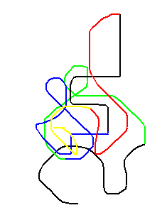
Below is the schematic of the Arduino Sketcher.

The sketcher allows the user to click on various parts of the canvas to determine where the lines start out. This allows for disconnected lines. It uses the joystick to determine where to draw the line and how quickly. The more the user shifts the joystick, the faster it draws lines. When the user holds the joystick down, the button triggers and a circle will be drawn on the canvas. The longer the button is held down, the larger the circle is. The buttons next to the joystick allow the user to select various colors indicated by the wire. There are buttons available that are colored and can be used to indicate color.
Code
Arduino Code
Below is the code on the Arduino side. The Arduino is mostly used to translate the controller and send commands to the Python side.
/****************************
Controller for Sketcher

Jennifer Case
13/06/2013
****************************/

//Declare pins
int redPin = 7;
int yelPin = 6;
int grnPin = 5;
int bluPin = 4;
int blkPin = 3;
int verPin = A0;
int horPin = A1;
int circlePin = 8;

int lastColor = 4;
long previousMillis = 0;
long interval = 200;
float numClicks = 0;

void setup() {
  Serial.begin(38400);

  pinMode(redPin, INPUT);
  pinMode(yelPin, INPUT);
  pinMode(grnPin, INPUT);
  pinMode(bluPin, INPUT);
  pinMode(blkPin, INPUT);
  pinMode(circlePin, INPUT);
  digitalWrite(circlePin, HIGH);
}

void loop() {
  //read values from color buttons
  int redBtn = digitalRead(redPin);
  int yelBtn = digitalRead(yelPin);
  int grnBtn = digitalRead(grnPin);
  int bluBtn = digitalRead(bluPin);
  int blkBtn = digitalRead(blkPin);
  //read and normalize values from the potentiameters
  float verPos = (analogRead(verPin)-504.0)/504.0;
  float horPos = (496.0-analogRead(horPin))/496.0;
  //read value of button
  boolean circleBtn = digitalRead(circlePin);

  //if either normalized value from the joystick is
  //essentially zero, make it equal zero
  if (verPos < 0.01 && verPos > -0.01) {verPos = 0;}
  if (horPos < 0.01 && horPos > -0.01) {horPos = 0;}

  unsigned long currentMillis = millis();
  char charBuf[5];

  //if enough time has passed and either potentiameter is not zero,
  //print out commands for both axes
  if(currentMillis - previousMillis > interval && (verPos != 0 || horPos != 0)) {
    Serial.print("X,");
    dtostrf(verPos, 4, 2, charBuf); //turn float to string
    Serial.println(charBuf);
    Serial.print("Y,");
    dtostrf(horPos, 4, 2, charBuf); //turn float to string
    Serial.println(charBuf);

    previousMillis = currentMillis; //reset the interval
  }

  //determine color and print it to sketcher if it was not the last color
  if (redBtn && lastColor != 0) {
    Serial.println("C,R"); //print command
    lastColor = 0;
  }
  else if (yelBtn && lastColor != 1) {
    Serial.println("C,Y"); //print command
    lastColor = 1;
  }
  else if (grnBtn && lastColor != 2) {
    Serial.println("C,G"); //print command
    lastColor = 2;
  }
  else if (bluBtn && lastColor != 3) {
    Serial.println("C,B"); //print command
    lastColor = 3;
  }
  else if (blkBtn && lastColor != 4) {
    Serial.println("C,K"); //print command
    lastColor = 4;
  }

  //while button on joystick is clicked,
  while (!circleBtn) {
    numClicks++; //increase counter
    circleBtn = digitalRead(circlePin); //read the button again
  }

  //if numClicks is more than zero,
  if (numClicks > 0) {
    Serial.print("O,"); //start printing command
    numClicks = numClicks/20000.0; //normalize the numClicks
    dtostrf(numClicks, 4, 2, charBuf); //int to string
    Serial.println(charBuf); //print the rest of the command
    numClicks = 0; //reset numClicks
  }
}
Python Code
Below is the Python code. It just translates the commands from the Arduino side and draws the appropriate lines on the canvas. It should be noted that this was coded for Python 3.
#! /usr/bin/python

from serial import *
from tkinter import *
import time


#Serial
ser = Serial("COM9",38400,timeout=0,writeTimeout=0)
time.sleep(1)

#initialize positions
xPos = 500
yPos = 300

#function for making a circle
def drawcircle(canv,x,y,rad,color):
    canv.create_oval(x-rad,y-rad,x+rad,y+rad,width=0,fill=color)

#function for mouse click
def goToClick(event):
    global xPos
    global yPos
    xPos = event.x
    yPos = event.y

#Main window
root = Tk() #Tk is a function that makes a class
root.wm_title("Canvas Sketch")
root.config(bg="#8D8A8A", bd="0")

#make the sketcher canvas
sketcher = Canvas(root, width=1000, height=600, bg='white')
sketcher.grid(row=0, column=0)
sketcher.bind('<Button-1>', goToClick)

#log = Text(root, width=50, height=8, takefocus=0)
#log.grid(row=1, column=0, padx=2, pady=2)

#initializations
color = 'black'
verPos = 0
horPos = 0

def runLoop(event=0):
    ln = ser.readline() #get command
    lineStr = ln.decode(encoding='UTF-8')
    #log.insert('0.0',lineStr)

    #print(lineStr)
    #initializations
    Xline = 0
    Yline = 0
    circline = 0
    newLine = 0

    #other neccessary variables
    global verPos
    global horPos
    global xPos
    global yPos
    global color

    #determine selected color
    if "C" in lineStr:
        for line in lineStr.split(','):
            if "R" in line:
                color = 'red'
            if "Y" in line:
                color = 'yellow'
            if "G" in line:
                color = 'green'
            if "B" in line:
                color = 'blue'
            if "K" in line:
                color = 'black'

    #get X value
    elif "X" in lineStr:
        if len(lineStr) > 6: #make sure length is appropriate
            for line in lineStr.split(','):
                if Xline == 1:
                    #take value from lineStr
                    verPos = float(line.strip("\n \r"))*-1 #fix direction
                    #print(verPos)
                    Xline = 0
                elif Xline == 0:
                    Xline = 1

    #get Y value
    elif "Y" in lineStr:
        for line in lineStr.split(','):
            if Yline == 1:
                #take value from lineStr
                horPos = float(line.strip("\n \r"))
                #print(horPos)
                Yline = 0
                newLine = 1 #indicates that a line is ready to be drawn
            elif Yline == 0:
                Yline = 1

    #draw circle
    elif "O" in lineStr:
        if len(lineStr) > 4: #checks length
            for line in lineStr.split(','):
                if circline == 1:
                    #gets value
                    circDiam = float(line.strip("\n \r"))
                    #draw circle
                    drawcircle(sketcher,xPos,yPos,5*circDiam,color)
                    circline = 0
                elif circline == 0:
                    circline = 1

    if newLine == 1:
        newY = yPos+5*verPos #finds new end position
        newX = xPos+5*horPos #finds new end position
        sketcher.create_line(xPos, yPos, newX, newY, fill=color, width = 2)
        xPos = newX #adjusts end position
        yPos = newY #adjusts end position

    root.after(10, runLoop)

runLoop()

root.mainloop()
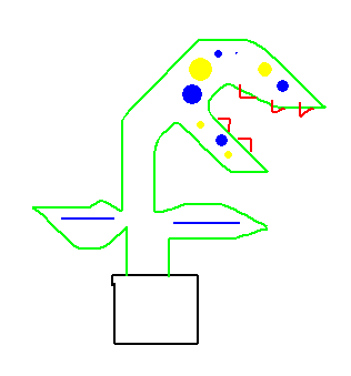
Example of Sketches
Computer Power Supply
Computer Power SupplyIntroduction
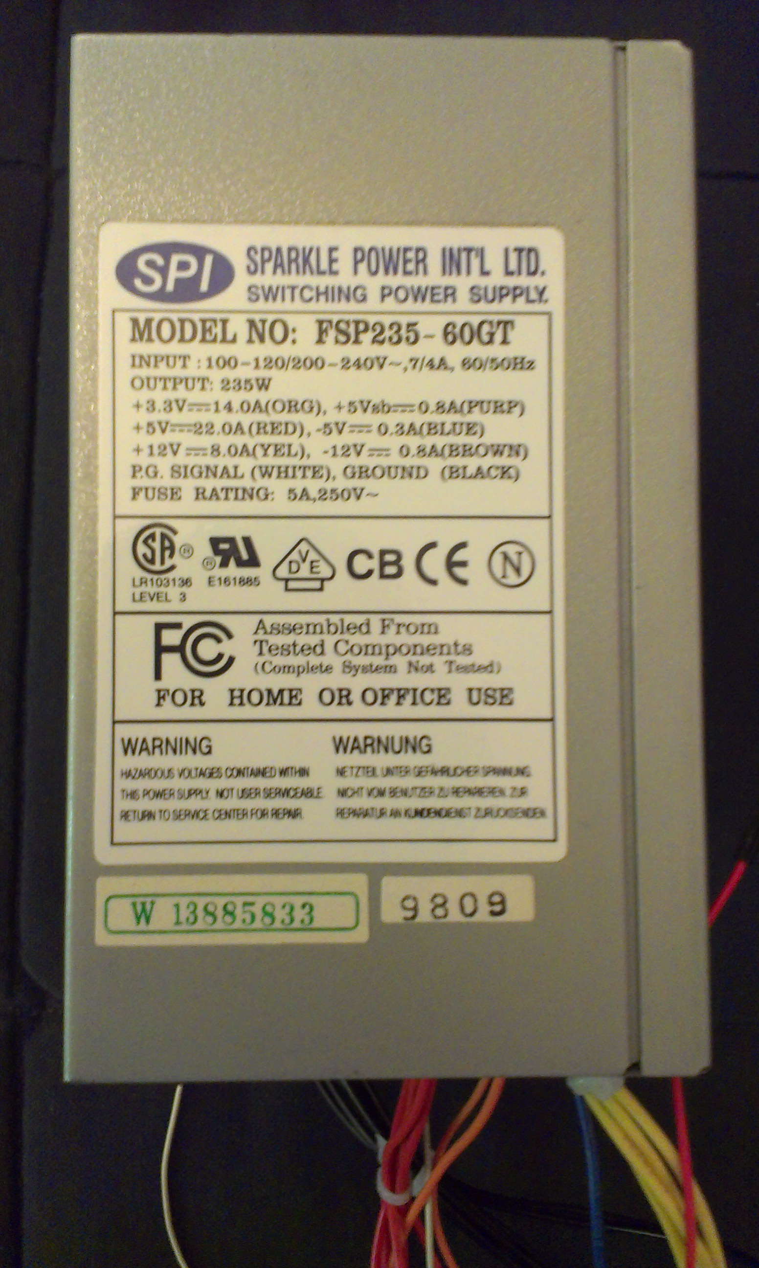
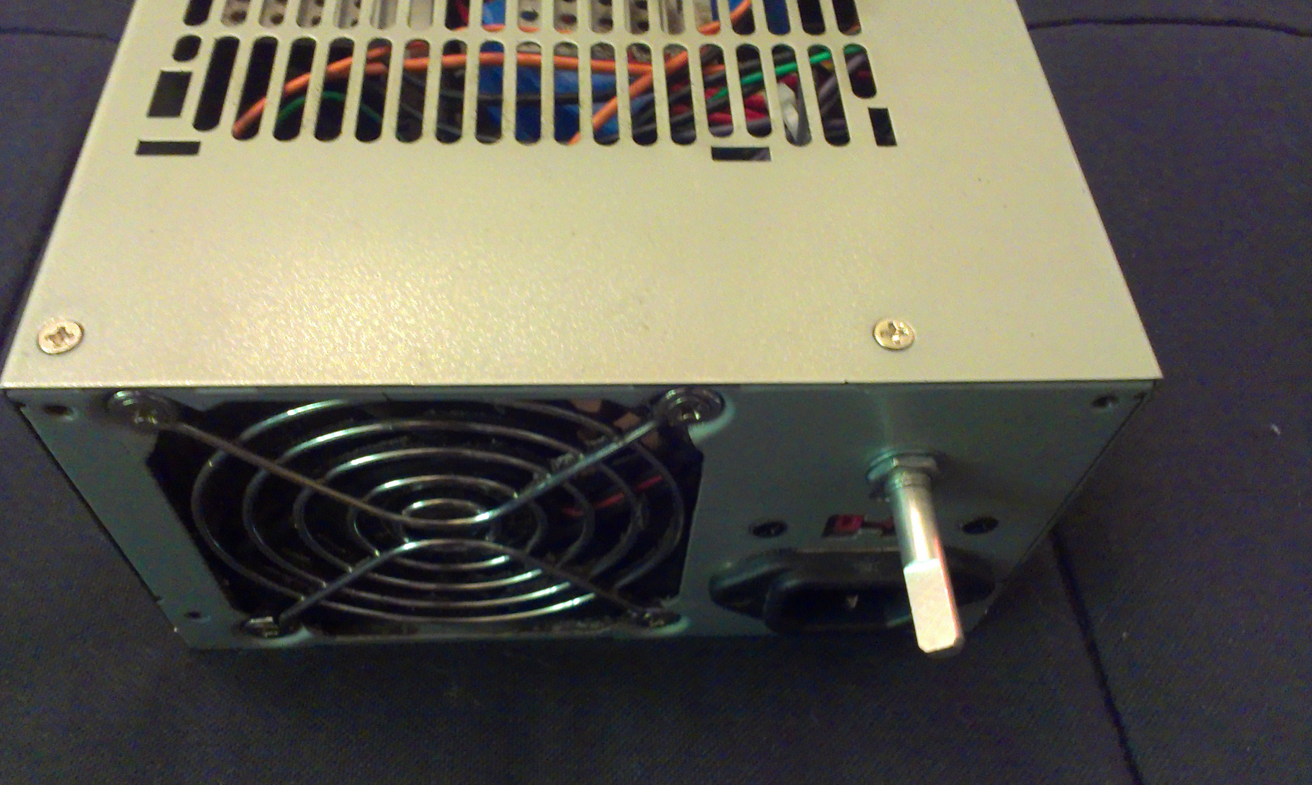
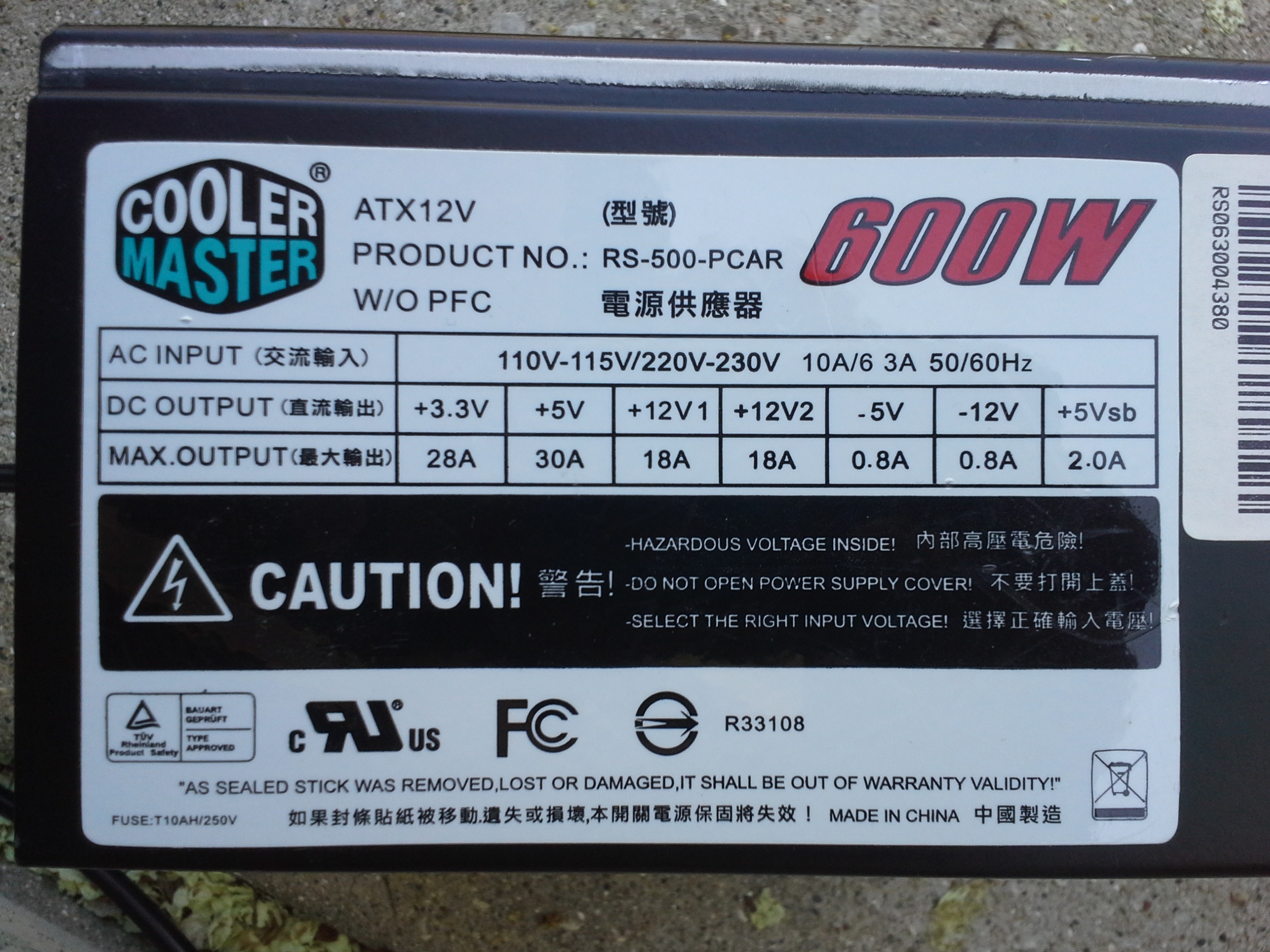
A lot of us have an old desktop computer we don't want anymore and it's good to re-use components. You'll find in each standard sized desktop, an ATX power supply. It's a standardized form factor for AC-to-DC power conversion with +3, +5, +12, and sometimes -5 and -12 VDC rails. If you look on the side, there is a sticker that will say what power it is rated to output.
Most power supplies are rated for usage in the range of 300 Watts to 600 Watts. High end ones go from 700 to 1200 Watts. That's not "toy" power. It can be dangerous and these things don't seem to have any fuses or anything in them. I melted a +5VDC wire for a few seconds when it accidentally contacted a ground. You could definitely start a fire with this and maybe hurt yourself. That being said, it is nice to have a nearly unlimited and somewhat well regulated power supply for no cost. You can get them new for about 20$ too, which seems like a good deal due to the variety of standardized voltages available.
It is not entirely straightforward to use these. They don't just turn on when they get power and there is no button for it. It is designed to be managed by an ATX compatible motherboard on computer. Basically, you need to short a specific pin to ground with a specific resistance (or use a potentiometer, like I did).
Completed Project Gallery:
Parts
- A computer (ATX) power supply
- A potentiometer OR an appropriate resistor and toggle button
- A green LED for the power indicator
- A red LED to show that the supply is on
- Two resistors (220-1000 Ohm) for the LEDs
- Binding Posts (optional)
- Voltage Regulators (optional)
Planning
If you want to add a button or potentiometer to turn it on, you'll need to cut a hole for it in the back. Potentiometers and certain buttons work nice because all you need to do is drill a hole of the right size and you can easily attach it with a nut and lock washer.
If you want some indicator LEDs, you'll have to drill holes for those too - probably on the front somewhere. You will need to open up the power supply and look carefully for a place to drill that won't damage the components.
Wiring
The Standard Connectors
| Color | Signal | Pin | Pin | Signal | Color |
|---|---|---|---|---|---|
| Orange | +3.3 V | 1 | 13 | +3.3 V | Orange |
| sense | Brown | ||||
| Orange | +3.3 V | 2 | 14 | −12 V | Blue |
| Black | Ground | 3 | 15 | Ground | Black |
| Red | +5 V | 4 | 16 | Power on | Green |
| Black | Ground | 5 | 17 | Ground | Black |
| Red | +5 V | 6 | 18 | Ground | Black |
| Black | Ground | 7 | 19 | Ground | Black |
| Grey | Power good | 8 | 20 | Reserved | N/C |
| Purple | +5 V standby | 9 | 21 | +5 V | Red |
| Yellow | +12 V | 10 | 22 | +5 V | Red |
The standard connectors, ATX and Molex, will both be removed and reorganized into something more like a lab power supply than one that can only power a desktop computer.
The ATX connector has 20 pins and a clip on one side: 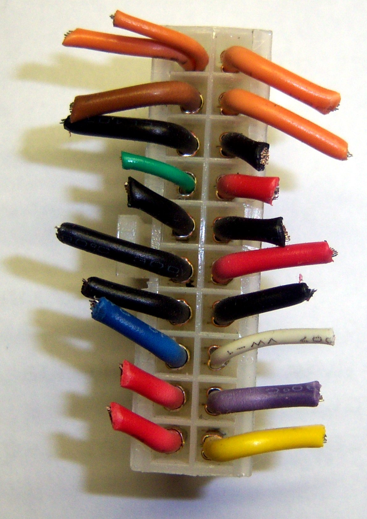
Note that the pins in the photo are flipped horizontally from the pins according to wikipedia. Also, some of those pins don't match up. The colors seem to be accurate though. You may wish to look for a version of the ATX table that matches the configuration of your power supply.
If you have that smaller orange/brown wire on Pin 13, just cut it off completely. It is not very useful and just confuses things. On mine, it was orange, so I kept thinking it was supposed to be 3.3V.
The ON Switch
Turning the power supply on isn't entirely straightforward. It won't just turn on when you plug it in.
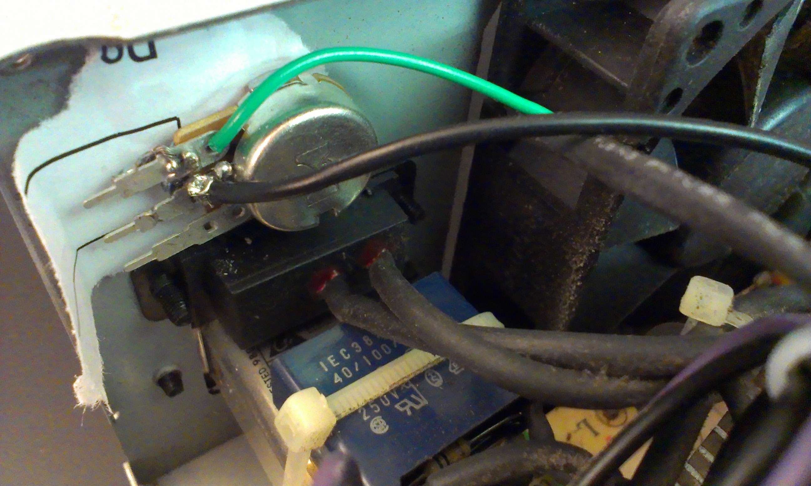
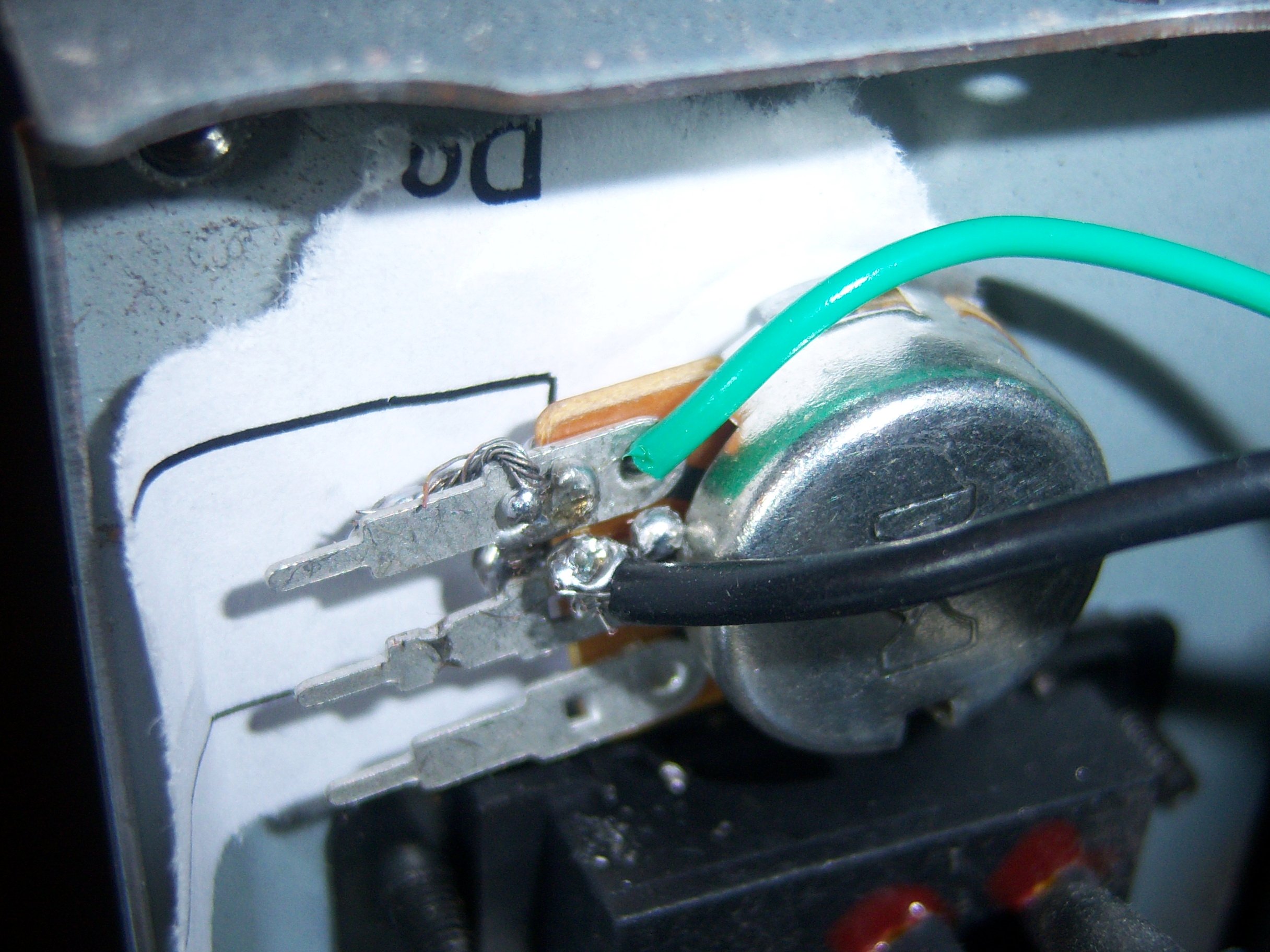
You can touch the green wire, which is the "Power On" (aka PS_ON) to a Ground (black wire). However, it needs a specific resistance. Otherwise it will just turn on for a fraction of a second and then turn back off. Rather than just trying out what resistance it needed, I used a potentiometer. If you want to use a button, I'd still use the potentiometer to experimentally determine the range of values you can use for the resistance.
Be very sure when testing how to turn it on that you don't shock yourself, or have any of the leads touching each other. At this point, you should only really need to have cut the green wire out of the 20 pin ATX molex connector and any of the black grounds.
Clearly, I did not do a great job of soldering this thing. It was actually my first time ever soldering, and it works. Minor victory.
The green wire can go on either end of the potentiometer (pot) - all it will change is which end has higher resisistance. The ground goes on the middle pin. I would guess you could probably even flip these wires and it would still work.
If you want to use a button, try turning on the power supply with the potentiometer a few times. Get a multimeter / voltmeter and see what the resistance is of the potentiometer between the two pins you are using. That will be the resistance you should target between your button.
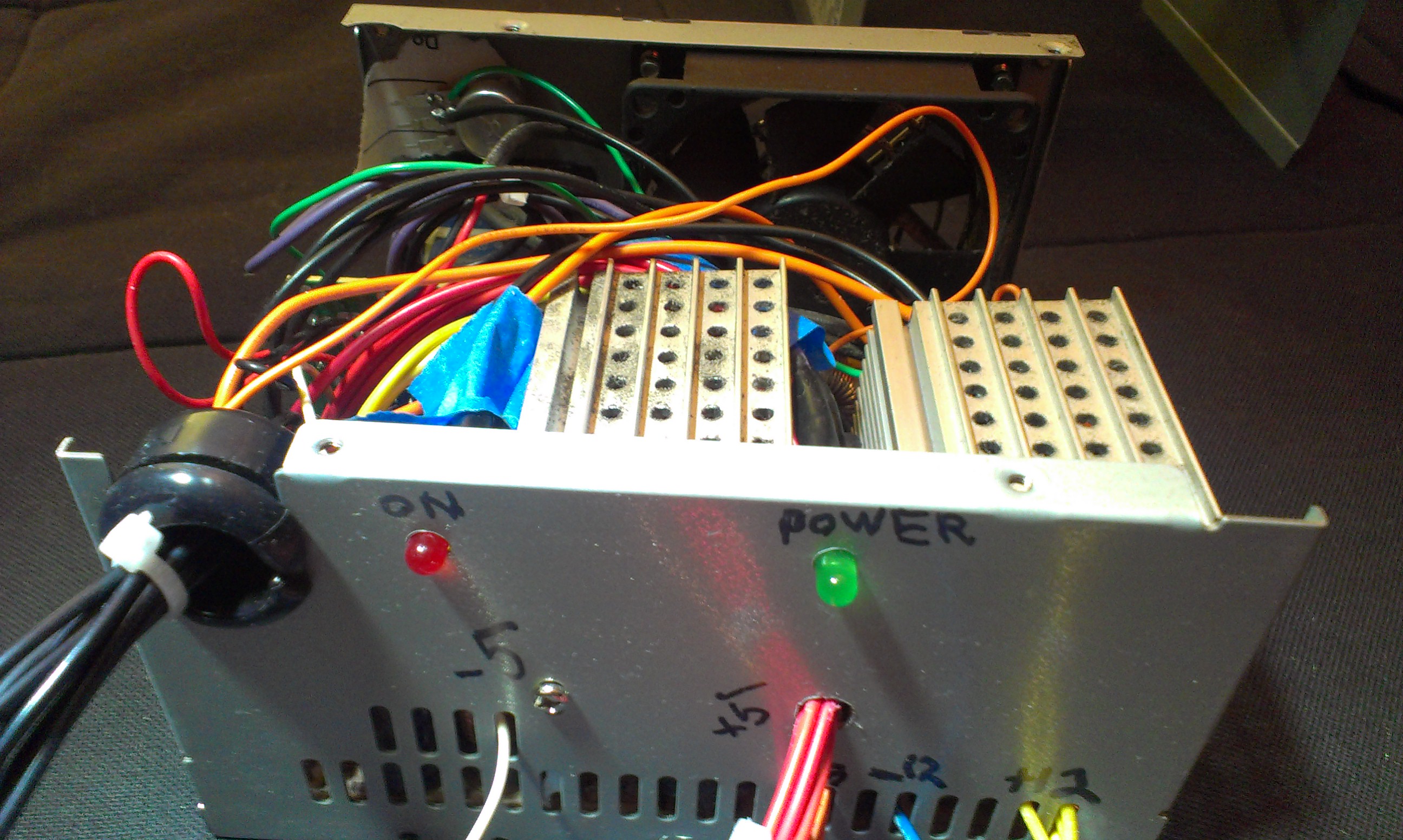
Power LEDs
 If you want an LED to be on whenever the powersupply has power - even if the power supply isn't on - you can use the purple wire, which is labelled as the +5V standby pin. So, just connect an LED+resistor combination that can deal with a 5VDC connection.
To mount the LED, I did not use any sort of clips or brackets. I just drilled a hole and taped the wires so the LED should stay in place. It isn't fool proof or professional looking, but it gets the job done.
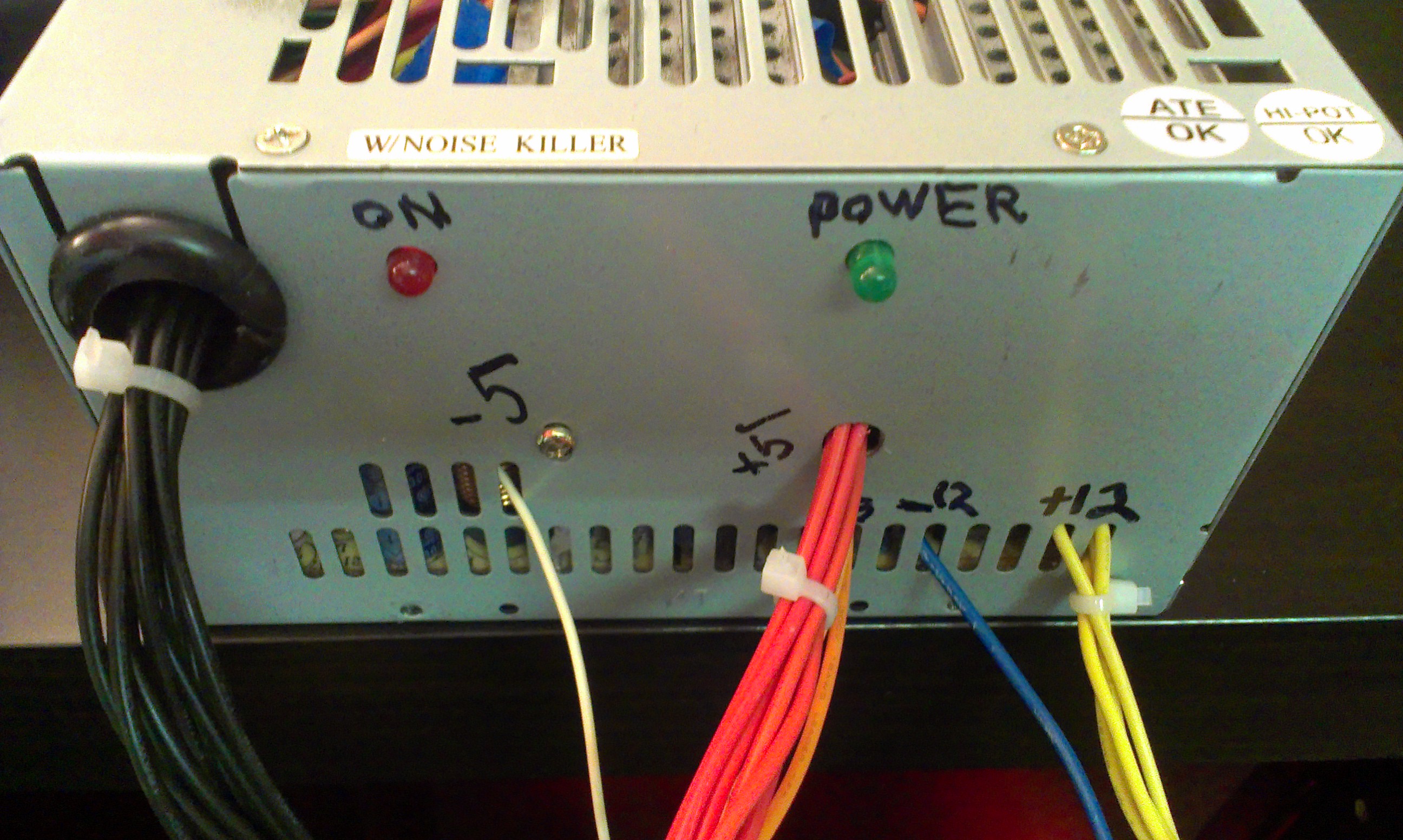
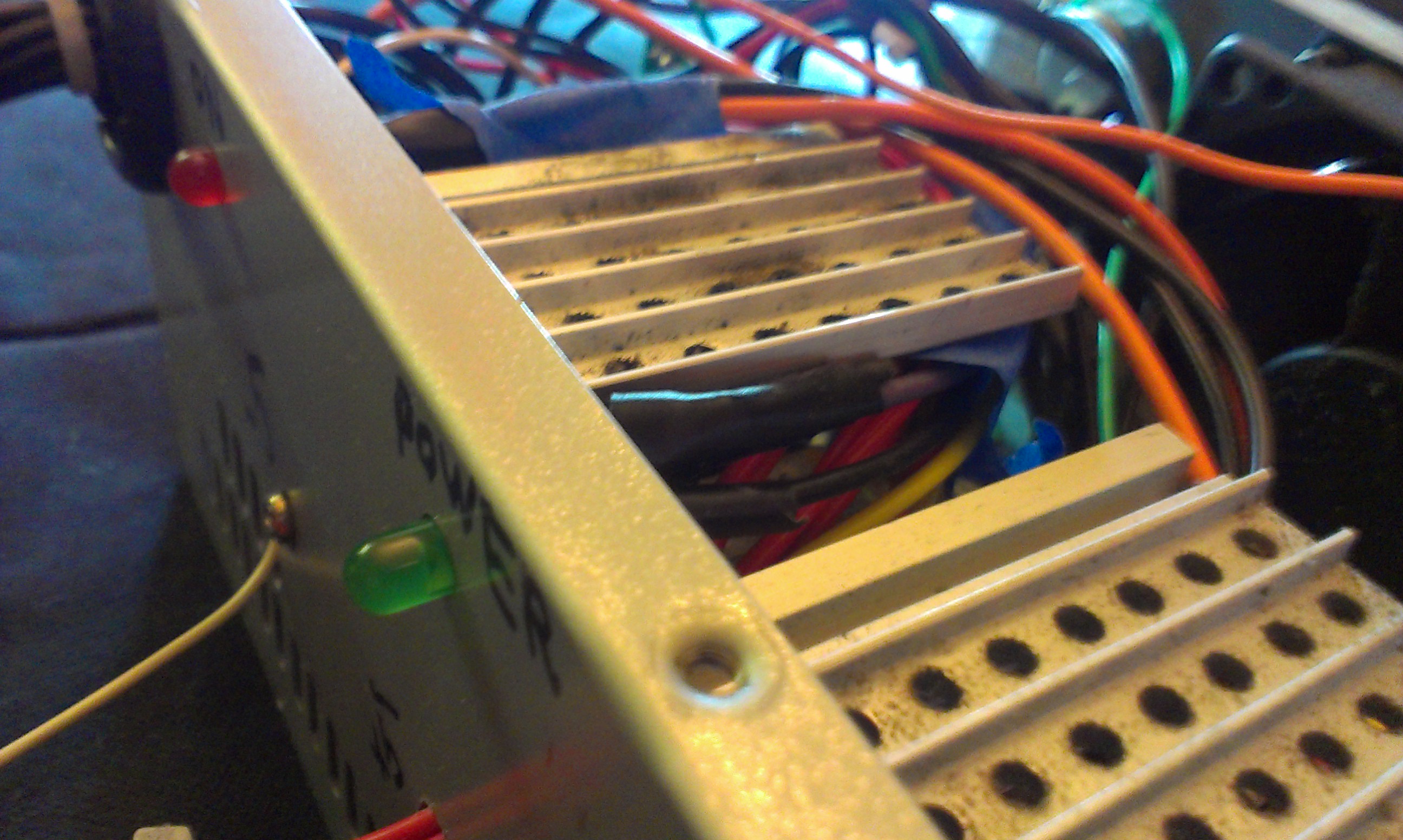
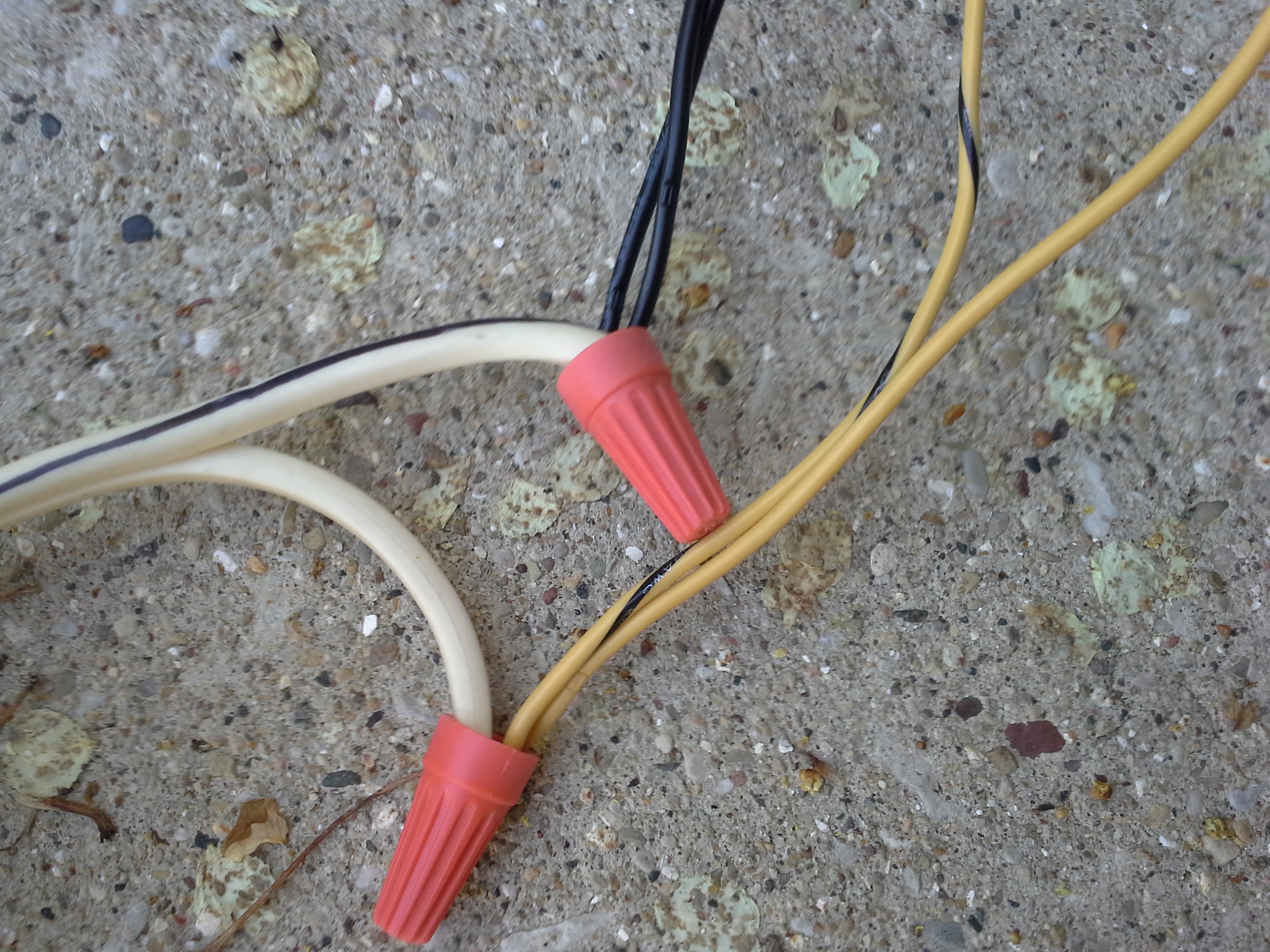
Organizing Leads
This is the most creative part of the project. You can drill holes, use the existing hole, or try to wedge them through the grill of the plate. I opted to try them all. I wanted to have the most seperation between each of the different types of leads. This allowed me to also label them.
There are definitely some much more elegant solutions to this, such as using banana / twist mounts ( binding posts ) instead of exposing the wires. The case could also be removed altogether and simply put the power supply directly into your project's chasis.
DJI ESC and Brushless Motor
DJI ESC and Brushless MotorIndrocution
These parts are designed to be used in a quadrocopter. They are sold as replacement parts to pre-built quadrocopters, but work well as interchangable parts. This is documention on the specs and how to use the parts, since none is really provided.
I have modelled these parts in Creo Parametric. However, since I am using the student edition, it would likely be uselless to anyone who wants the part for their own project since it supposedly will only work with other student licenses. Furthermore, I'm not sure the license would even allow me to do that. I am not aware of a reason why I can't show you the results of the model like diagrams and renders though.
DJI ESC
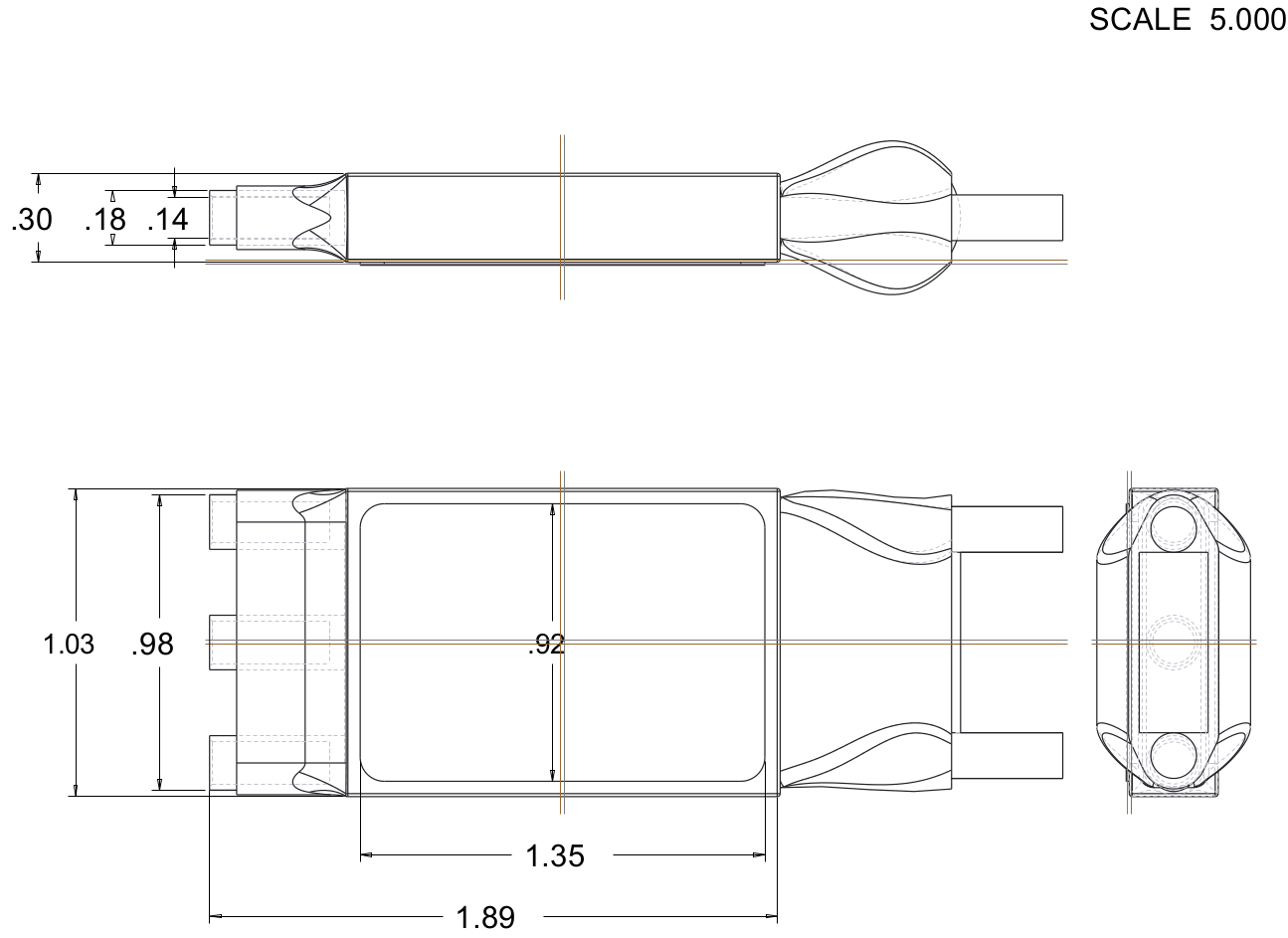
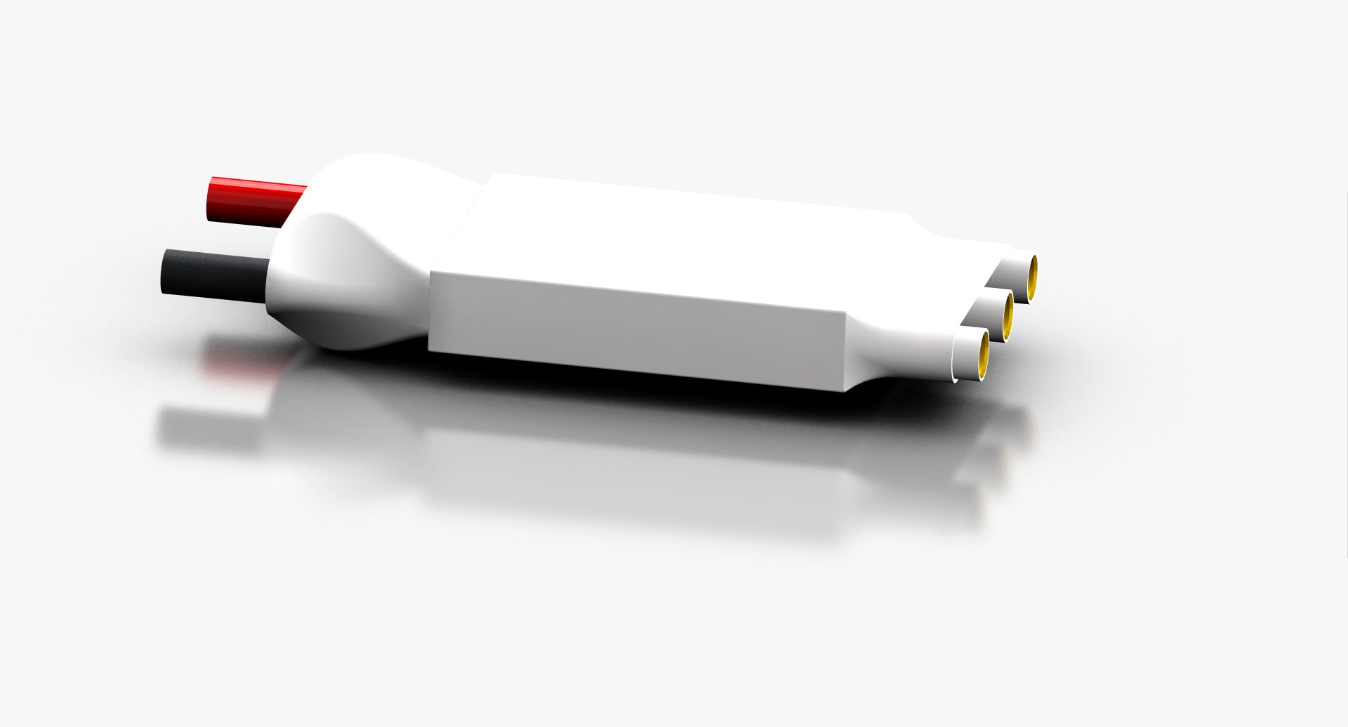
Note that I did not bother to dimension the lump where the wires come out because the shape is so irregular and varies between each individual one.
Specs
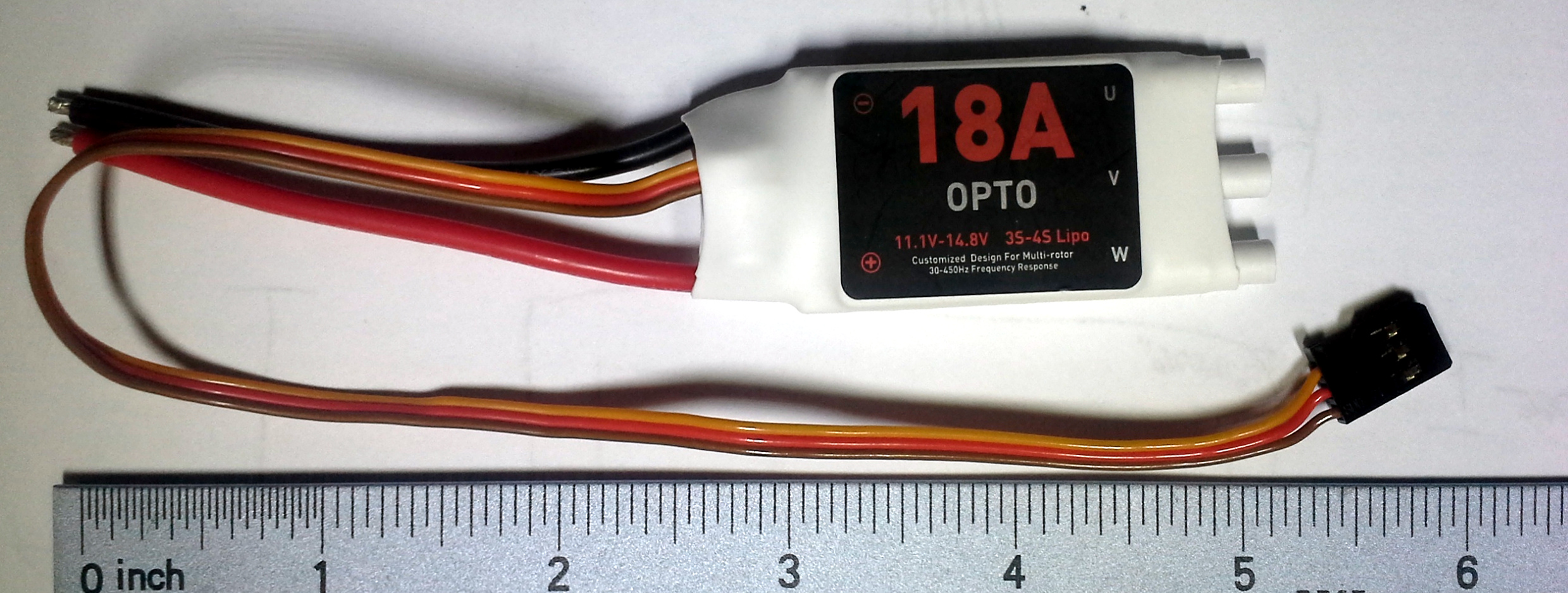
The name on the label is simply 18A. You could call it a DJI Opto-coupled electronic speed controller.
| Current | Voltage | Battery Compatibility | Frequency Response |
|---|---|---|---|
| 18 A | 11.1-14.8V | 3S-4S LiPo | 30-450 Hz |
When I weighed it I found it is 0.815 oz. The ESC outputs 3.33V on the red wire.
Signal
Some ESCs have a complicated (and undocumented) startup routine. It allows them to calibrate their input signal range. In this case, we have such control over our controller that it is substantially easier to calibrate the controller than the ESC.
According to the DJI wiki on the ESC, as well as the sticker on the actual device, it can accept signals from 30 Hz to 450 Hz. The Arduino Servo library outputs a pulse every 20ms, which translates to a frequency of 50Hz, which is within the allowable range. To set the speed, use Servo.writeMicroseconds( pulseDuration ). According to Arduino, a servo can be set to no speed with a by passing the parameter a value of 1000 uS, and full speed by passing 2000. However, according to this wiki specifically about ESCs, the range is typically from 500 uS to 2500 uS. This specific one seems to take a range from 1150 to 1950.
Motor
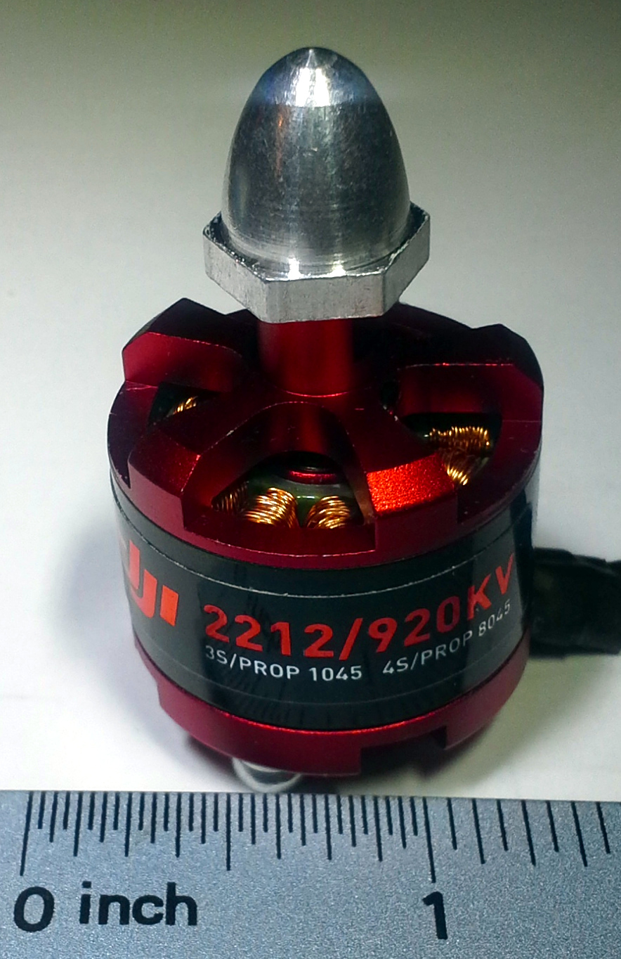
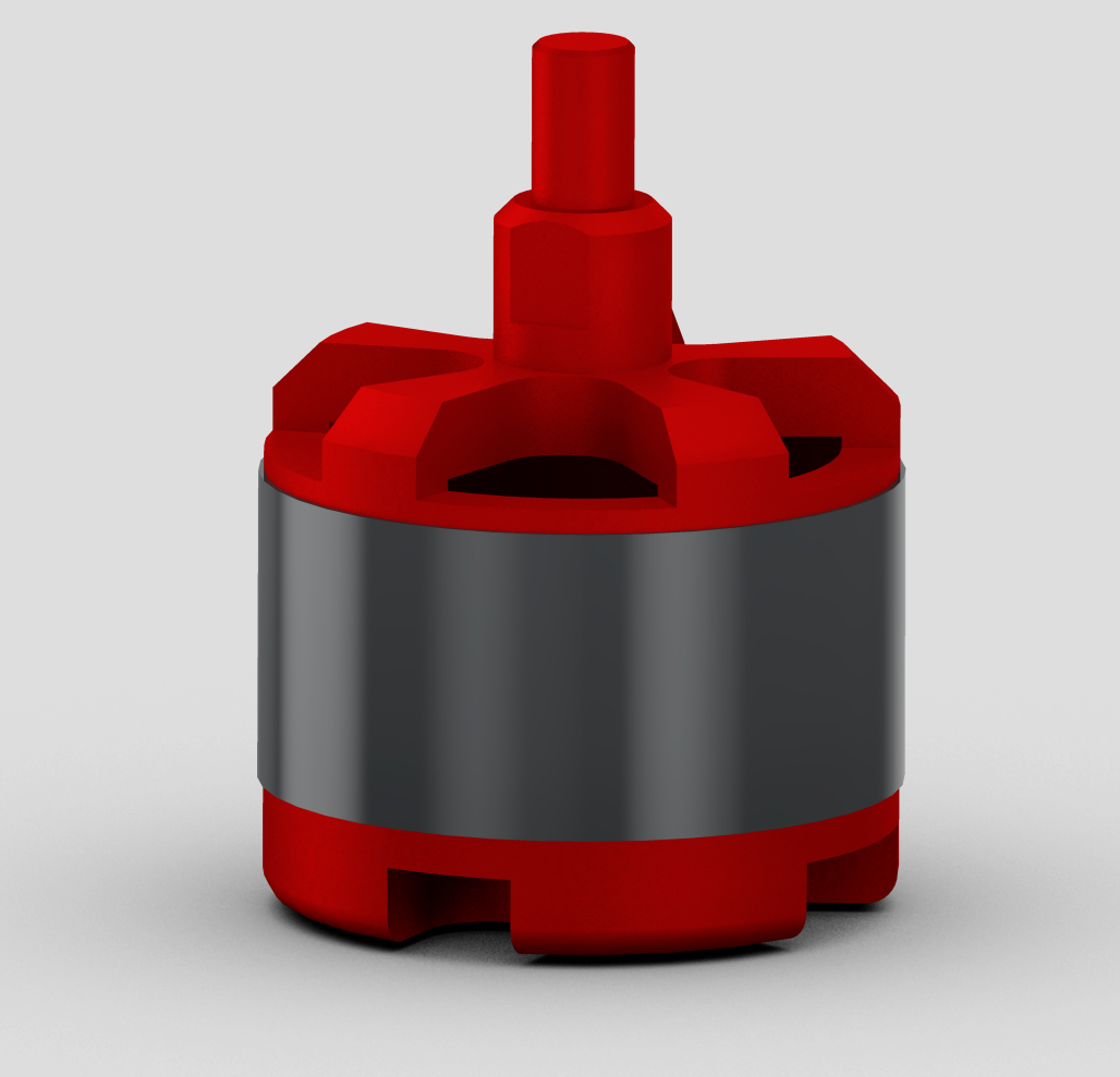

Specs
The full name as far as I can tell, is: DJI Brushless outrunner 2212/920K Motor F330-550.
| rpm/V | Shaft | 3S Battery / Prop | 4S Battery / Prop | Current | Max Current |
|---|---|---|---|---|---|
| 920 kv | 8mm | 11.1V / 10x4.5 | 14.7V / 8x4.5 | 15-25A | 30A |
I have weighed it myself at 1.980 oz (56.1321 grams). It is about 1.25 inches in diameter, and about 2 inches tall.
Lift Test
I tested the signal ranges for the ESC and the corresponding lifts for two kinds of DJI propellers.
Parts
- DJI 30A ESC
- DJI 2212 920kv motor
- An aluminum/steel beam about 1/8" thick to mount the motor to
- 2 to 4 M3 (3mm) screws
- 2 to 4 M3 (3mm) lock washers
- Drill
- Drill bits capable of drilling into metal
- 9/64" drill bit for outer mounting holes
- 9/32" drill bit for inner shaft hole
- A power supply capable of 11-13v at 18 A
- Use a very expensive lab power supply
- OR a hacked desktop computer power supply
- Use 12v rails
- Must support at least 18A on 12V rails
- I used a Cooler Master Extreme Power Plus 500W
- A block of wood (2x4, 4x4, etc)
- DJI 8045 (8" diameter) propeller
- DJI 1045 (10" diameter) propeller
- A food scale or more scientific scale with a range of about 0-8lb
- Clamps
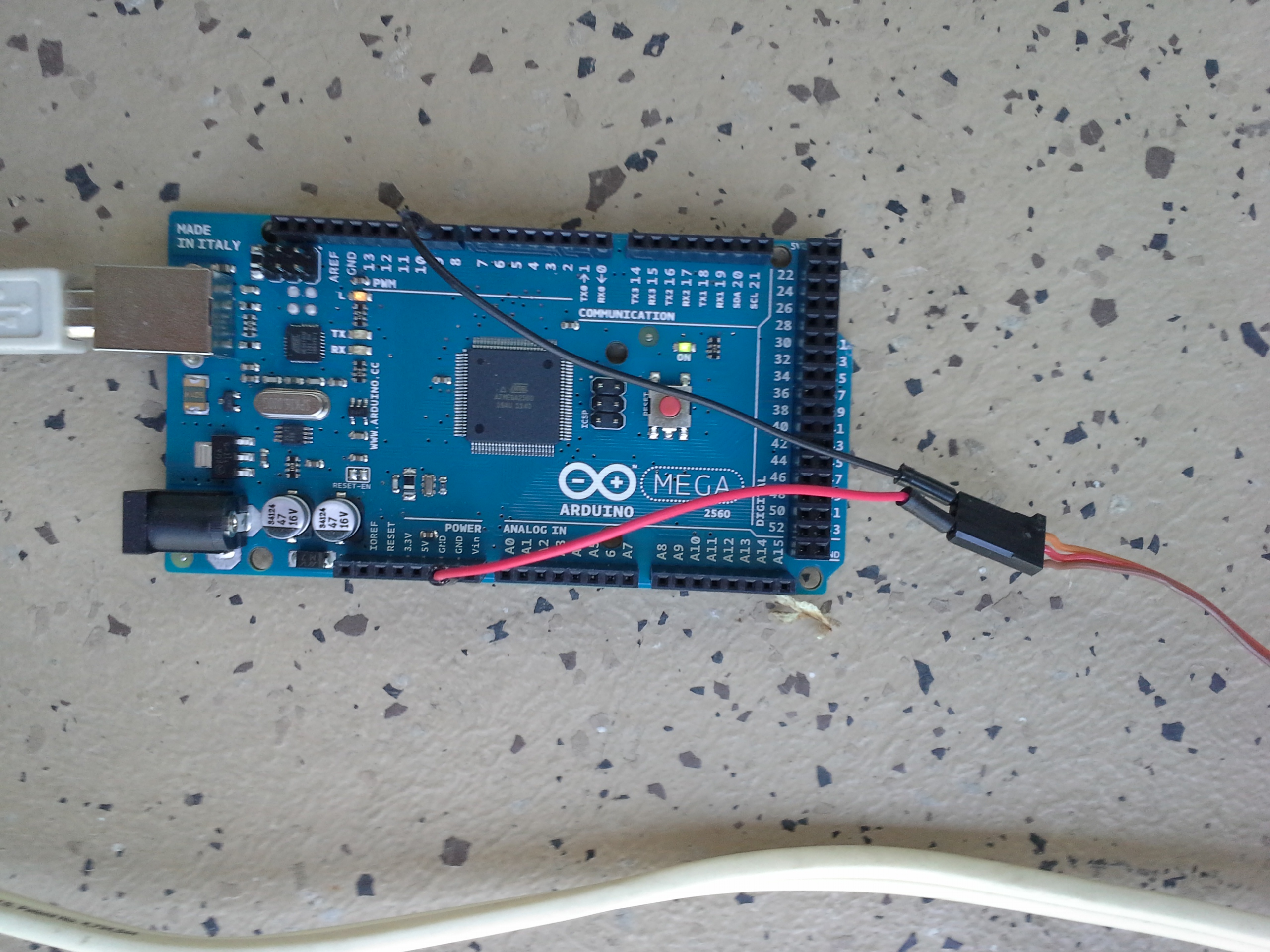
Wiring
The wiring is easy. I made a fritzing model of it though. You can download my parts at the bottom of this page.
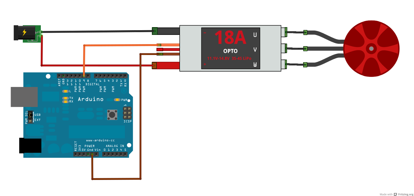
The ESC outputs a well regulated 3.33V on the small red wire, which is enough for some microcontrollers and Arduinos, but not the Arduino Uno or Mega. So the Arduino Uno would need a seperate power souce. The data pin can be any pin that the Servo library can use.
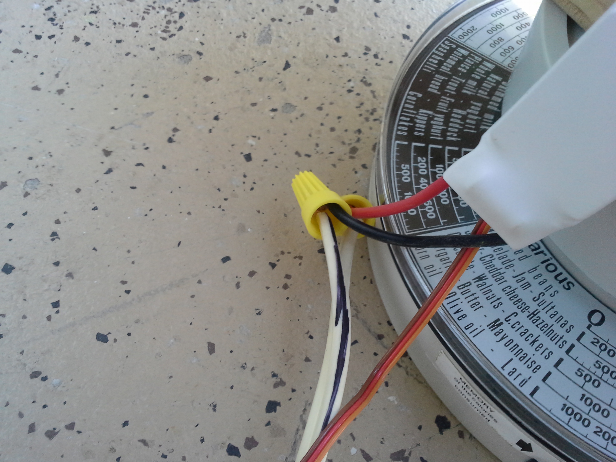
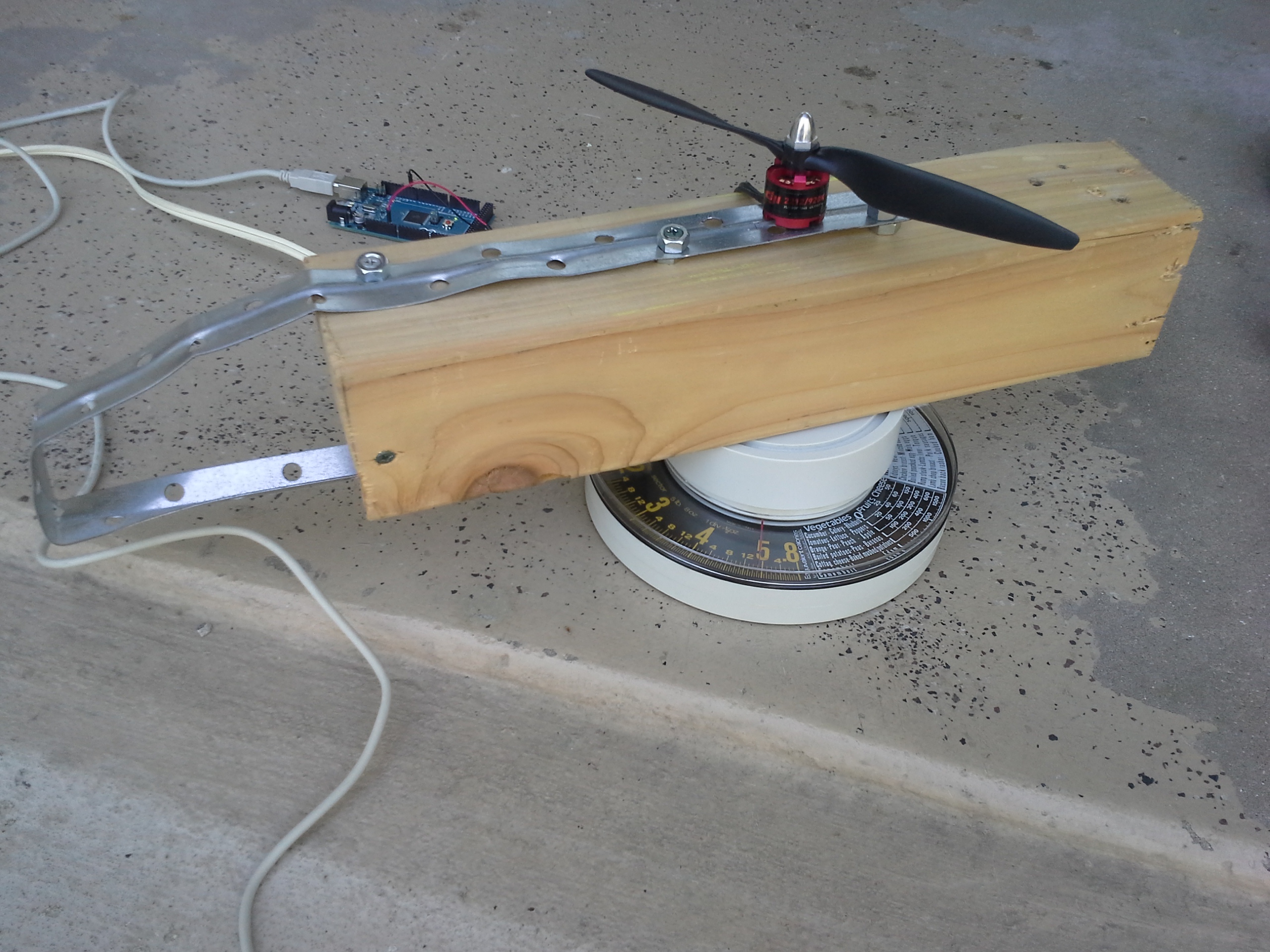
Setup
Using a desktop computer power supply capable of powering 36A of 12V to power the ESC and motor, it should have more than sufficient power. The testing rig was a very quickly put together device just intended to keep it firmly in place on the scale. The scale was not a particularly accurate one either, but it worked reasonably well.
Results
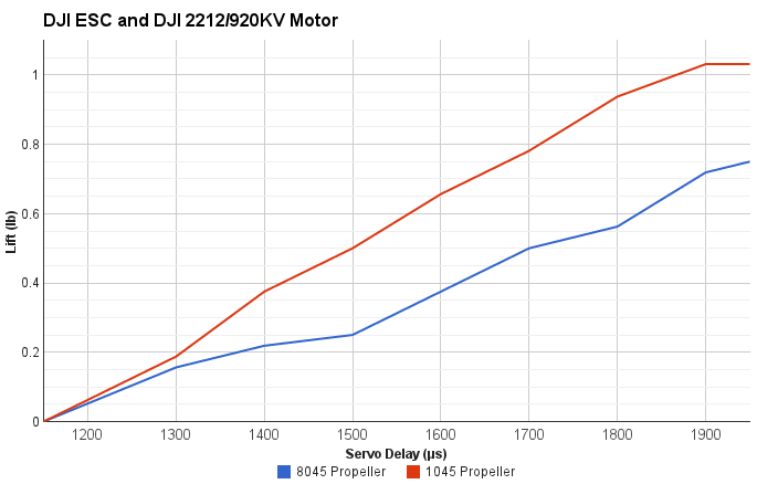
The most lift achieved on the 10" propeller was 1 pound. The most lift achieved on the 8" propeller was about 3/4 of a pound with a servo delay of 1950 microseconds.
A lot about the test is not perfectly accurate for my needs. It used 12v instead of 11.1. Also, the scale that was used was not very accurate either since the readings could be easily read wrong by an ounce. Furthermore, due to the off-center nature of the mounting bracket, the weight on the scale may not have been read perfectly well. Still, it provides a good guideline for how much the combination of parts can lift.
Most importantly, the 4 by 4 blocked more of the airflow than any chassis would, so one might expect to get even more lift than these measurements.
It also should be observed that there was no additional lift after 1900 on the 10" propeller, but the 8" one saw an increase. This could suggest that the ESC is reaching its amperage limit of 18A.
The motor was noticably warm after the 10" test, but was not at all during the 8" test. This leads me to believe that the 8" propeller would be substantially more efficient, if you don't need the extra lift.
Test Code
#include <Servo.h>

Servo myservo;  // create servo object to control a servo

int val;    // variable to read the value from the analog pin

void setup()
{
  Serial.begin(9600);
  myservo.attach(9);  // attaches the servo on pin 9 to the servo object
}

void loop()
{
  val = 1050;
  delay(500);
  myservo.writeMicroseconds(val);
  Serial.println(val);
}
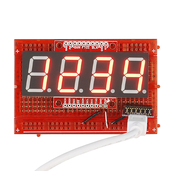
Divergence Meter
Divergence MeterBackstory
I want to make a divergence meter. A divergence meter is not a real thing. It's a fictional device from Steins;Gate to tell if the worldline (timeline) has changed substantially from an original world line (the alpha) - following the time travel theory popularized by John Titor. If you've never seen the show, you might still be interested in how to wire up a longer string of displays to get 8 digits instead of being stuck with just 4.
Goals
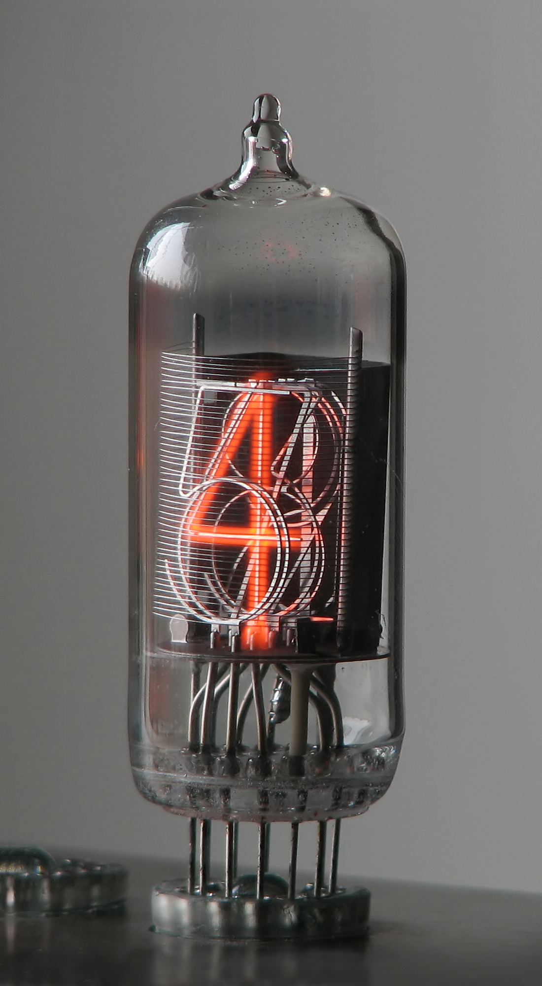
I'm not actually going to build a very accurate one. It turns out that that many Nixie tubes are kind of expensive (about $100), but you really should use them if you want to maintain authenticity. There are plenty of other tutorials on how to make one with nixie tubes, and you can even buy an offical one, which admittedly does not look all that accurate. The show specifically references Nixie tubes' cool factor, so it's really an important detail.
Also, it is obviously not going to be able to actually measure the attractor field, so it will instead randomly make up divergence values at random times. Also, according to canon, the divergence meter should cycle random numbers on the display quickly while the divergence number is changing for about a second.
To somewhat replicate its purpose, this system will change divergence number about once a day or perhaps longer. One could look to the divergence meter to try making a small change in their life. Very infrequently, the divergence number should jump to something above 1%. Larger numbers could be cause for celebration or trying larger changes in one's life.
Parts
If you choose to build yours with nixie tubes, your parts list will vary greatly from this, since you will also have to wire each segment to up seperately to your microcontroller, but also need to worry about power management. Nixie tubes need high voltage and low current, so switching segments on and off might require something like a high power shift register, or a logic level shifter to protect your Arduino microcontroller.
- 2x OpenSegment Serial Displays 20mm or 12.8mm (Sparkfun, $17ea)
- Hard Wire (8 segments)
- Arduino Micro without headers (Adafruit, $23)
- Enclosure for two displays side by side and a micro
- should leave micro USB port exposed or use a panel mount
The above parts list assumes you will want to solder the whole thing together permanently.
The total cost for this project, without using nixie tubes, is only about $57 plus whatever you use to make the case with. It is substantially safer, cheaper, and easier to make.
Wiring
The wiring here could not be easier if you're using the serial seven segment displays. The nixie tubes, however, will be nightmarish and will probably require making your own printed circuit board (PCB) to keep your sanity and to keep the device compact.
Change the i2c Address
Only hook up the first seven segment display. If you keep both on, you will have a problem due to the fact that both of the displays have the same address. So, both would react to the same commands. Fortunately, it can be easily changed with the right command code (0x80). By default, the address is 0x71. Change the address of the first display to just about anything but that. So, with just one display connected, run this:
#include <Wire.h>
void setup() {
  Wire.beginTransmission( 0x71 );   // Start I2C transmission to first display
  Wire.write( 0x80 );               // I2C Address Config command
  Wire.write( 0x42 );               // Set 7-bit address to 0x42
  Wire.endTransmission();           // Stop I2C transmission
}
void loop() {}
Connections
You will probably want to solder these connections instead of using headers and pins because it will save space and cost. However, it will make the changes somewhat more permanent. On the bright side, if you later decide you don't want a divergence meter, you can actually have it display just about anything - like the time perhaps.
To hook up these displays, simply connect the SDA and SCL pins on the Arduino Micro microcontroller to the SDA pin on the SDA and SCL pins on the display respectively. Likewise, connect the 5V from the Arduino to the + on the display, and the GND on the Arduino to the - on the display. Again, only do this for the one display.
Once you change the address of the first display, you can actually hook the other display up to the same wires. It might sound weird at first, but that's how i2c works. Check the sparkfun tutorial and see for yourself. The smaller serial7segment displays have a +,-,SDA, and SCL pin on each side to pass the connection through to the next one easily. You can do this yourself with just some wire though.
Code
#define DISPLAY1 0x71
#define DISPLAY2 0x42

#include <Wire.h>

unsigned long divergence = 337187; //or 409031
// displayed as:         0.337187

//Given a string, i2cSendString sends the first four characters over i2c
void i2cSendString(char *toSend, int addr) {
  Wire.beginTransmission(addr); // transmit to device #1
  for(byte x = 0 ; x < 4 ; x++) {  // for each of the 4 characters
    Wire.write(toSend[x]);         // Send the character from the array
  }
  Wire.endTransmission();          // Stop I2C transmission
}

void updateDisplay() {
  char first[5];
  char second[5];

  snprintf( first , 5, "%05d", divergence / 10000UL ); //pad with 0
  snprintf( second, 5, "%05d", divergence % 10000UL ); //pad with 0

  //move the second number to first place, then replace with space
  //it looks weird, but that's how the divergence meter is in the show
  first[0] = first[1];
  first[1] = ' ';

  i2cSendString(first , DISPLAY1);
  i2cSendString(second, DISPLAY2);

  Serial.print(first);
  Serial.println(second);

  // write the decimal place
  Wire.beginTransmission(DISPLAY1); // transmit to device #1
  Wire.write( 0x77 );               // send decimal command
  Wire.write( 1 << 3 );             // send the place using bitshift
  Wire.endTransmission();           // Stop I2C transmission
}

void newNumber() {
  // small percent chance to break divergence barrier
  if ( random(0, 100) < 5 ) {
    divergence = random(1000000UL, 1409031UL);
  }

  divergence = random(0UL, 999999UL);

  updateDisplay();
}


// when the divergence number changes
// the divergence meter cycles numbers randomly
// until a new number stabilizes

void changingNumber() {
  for( int cycle = 0; cycle < 100; ++cycle ) {
    divergence = random(0, 9999999UL);
    updateDisplay();
    delay( 30 );
  }
}

void setup() {

  // read the noise for some randomness
  // if analog input pin 0 is unconnected, random analog
  // noise will cause the call to randomSeed() to generate
  // different seed numbers each time the sketch runs.
  // randomSeed() will then shuffle the random function.
  randomSeed(analogRead(0));

  Serial.begin(19200); //for debugging
}

//increase this if you're impatient to change the divergence number
#define tdivider 10000UL
void loop() {

  changingNumber();
  newNumber();

  unsigned long wait = random(43200000UL , 604800000UL)  / tdivider;
  Serial.print("Waiting ");
  Serial.print(wait);
  Serial.println(" milliseconds before number change");

  delay(wait); // 12 hours to a week

}
Octobot Chassis
Octobot ChassisIntroduction
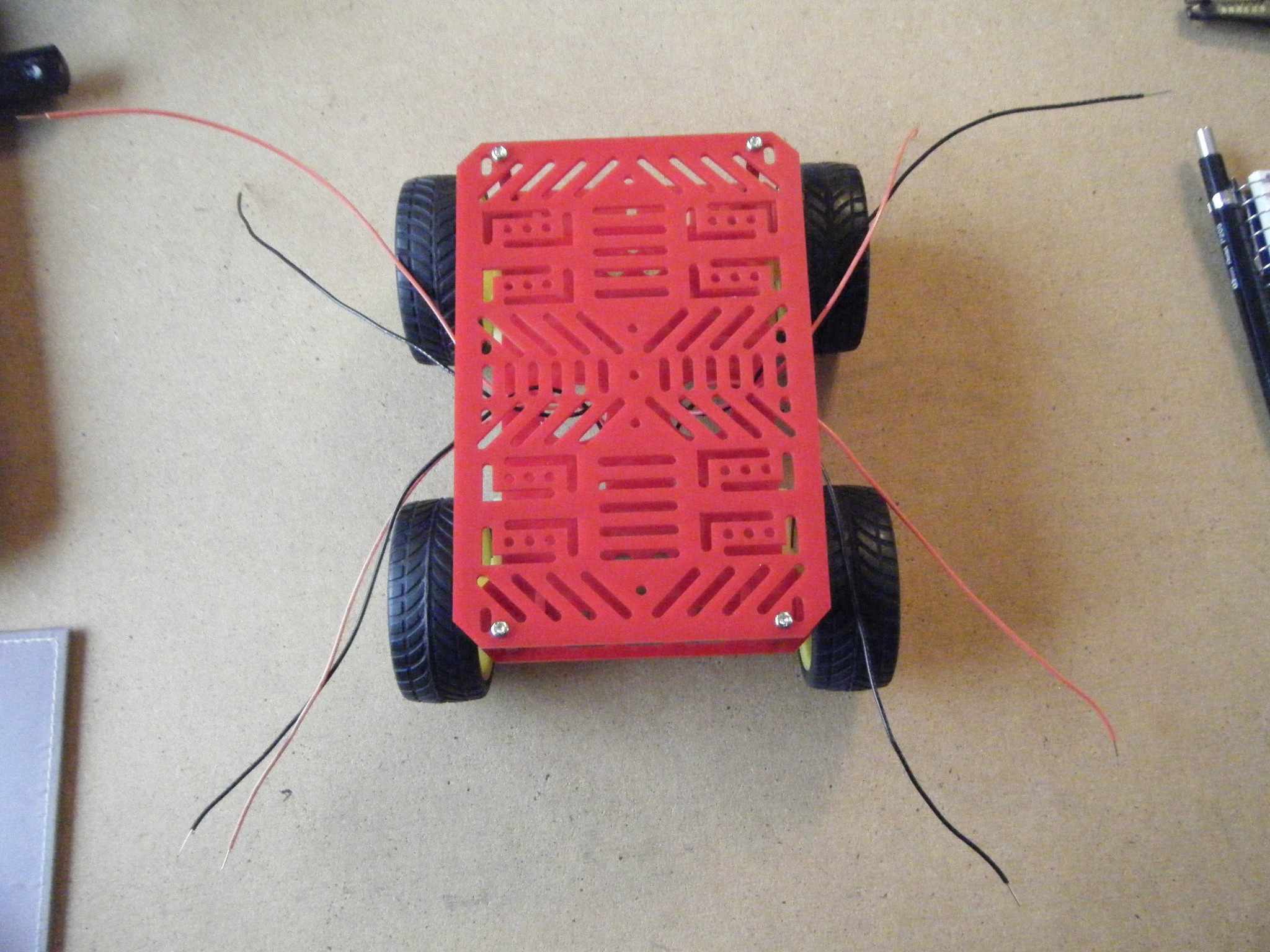 Octobot is the name of the robotic chassis that I do most of my testing on. It got it's name because it originally had eight wires sticking out because of the motors.
The picture to the right shows it in its unfinished form. The front two wheels were removed and exchanged for a ball caster for manuverability.
Once completed, the chassis makes an excellent inexpensive platform for an Arduino robot.
The Making of Octobot
Parts:
- 4WD Chassis and Motors from Jameco
- 1" Ball Caster from Pololu
- 3/8" Spacer
- Screwdriver
- Drill
- Solder and Soldering Iron
- Wires
Construction:
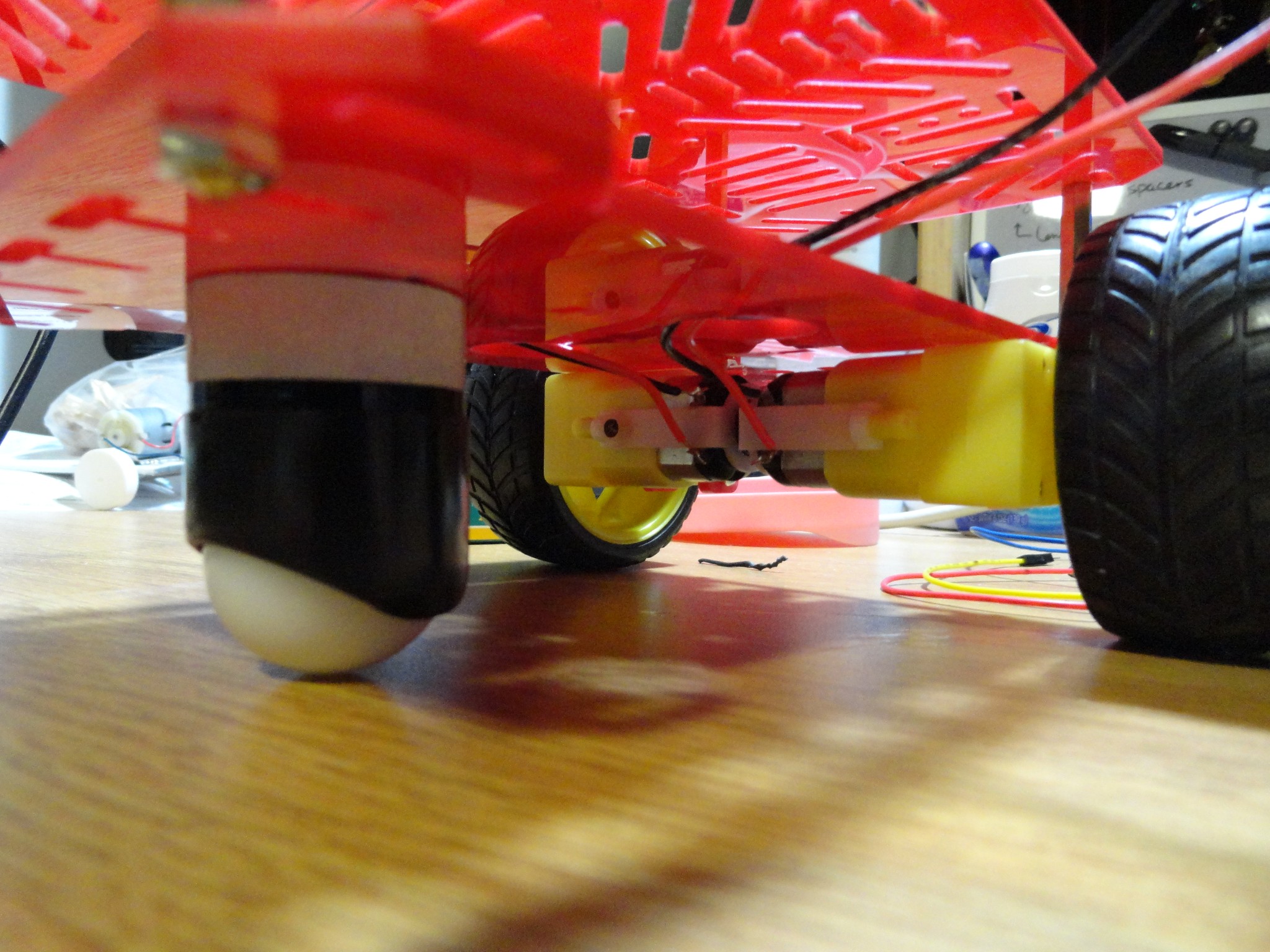 As can be seen, Octobot started out with four motors and four wheels. It was quickly discovered that this was not desirable if the robot had to perform tight turns. Therefore, Octobot was altered to have two wheels and a ball caster.
This required getting a 3/8" spacer made from aluminum to get a more appropriate height. Holes had to be drilled in the chassis to align with the ball casters holes. The alterations were fairly quick and simple to do. This is a cheaper alternative to some of the robotic platforms available.
Uses
Octobot is used to test most of the code I post if it directly pertains to use on a robot. Two arduinos can easily be attached via standoffs to the top of Octobot.
Simple Security System
Simple Security SystemIntroduction
Who hasn't wanted to monitor what goes on when they aren't there. When I was little, I was always curious about whether or not anyone was going into my room and would have loved a camera monitoring system. It may even be a good idea to have a simple security setup for an apartment.
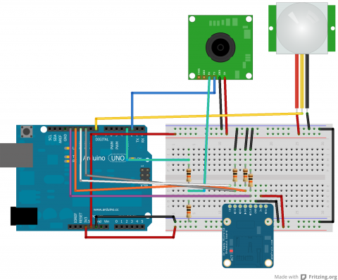
This tutorial shows how to set up a PIR sensor along with a small TTL camera and an SD card to capture images whenever there is movement in the monitored area.
The necessary libraries are: SoftwareSerial (for the camera) and SDFat (for the SD card).
Parts
- PIR Sensor
- TTL Camera by Linksprite
- SD Card Breakout Board
- SD Card
- 2 10k Resistors
- 3 other Resistors (I'm not sure if size matters, but mine were all above 1k)
- Wires
- Arduino
Schematic
Code
Arduino
Below is the code:
/***************************
PIR Motion Detection - Camera Capture

by Jennifer Case
5/21/2013

Parts:
-PIR Sensor
-SD Card Breakout Board
-TTL Camera

Pin 2,3 - Camera
Pin 8 - PIR Sensor
Pin 10 - CS/D3
Pin 11 - CMD
Pin 12 - D0
Pin 13 - CLK
****************************/
#include <SoftwareSerial.h>
#include <SdFat.h>

//SD Card
SdFat sd;
SdFile myFile;
int picCnt = 0;

//Camera
byte incomingbyte;
SoftwareSerial cameraSerial = SoftwareSerial(2, 3);   //Configure pin 2 and 3 as soft serial port
int a=0x0000,j=0,k=0,count=0;   //Read Starting address
uint8_t MH,ML;
boolean EndFlag=0;

//Declare pins
const int chipSelect = 10;
int pirPin = 8;

void setup() {
  Serial.begin(19200); //start serial
  cameraSerial.begin(38400); //start serial with camera

  // Initialize SdFat or print a detailed error message and halt
  // Use half speed like the native library.
  // change to SPI_FULL_SPEED for more performance.
  if (!sd.begin(chipSelect, SPI_HALF_SPEED)) sd.initErrorHalt();

  SendResetCmd(); //allows camera to take pictures
  delay(3000); //delay necessary for camera reset
}

void loop() {
  int val = digitalRead(pirPin); //read from PIR sensor

  //when val is HIGH, there is motion -> take pictures
  if (val == HIGH) {
    //create title for images
    char photoTitle[25] = {};
    sprintf(photoTitle, "pic%d.txt", picCnt);
    //Serial.println(photoTitle);

    //make sure file can be created, otherwise print error
    if (!myFile.open(photoTitle, O_RDWR | O_CREAT | O_AT_END)) {
      sd.errorHalt("opening photoTitle.txt for write failed");
    }

    //Serial.print("Writing to file...");

    SendTakePhotoCmd(); //take photo
    delay(200); //delay to make sure there is no drop in the data
    //Serial.println("Start pic");

    while(cameraSerial.available()>0) {
      incomingbyte=cameraSerial.read(); //clear unneccessary serial from camera
    }
    byte b[32];

    while(!EndFlag) {
      j=0;
      k=0;
      count=0;
      SendReadDataCmd(); //command to get picture from camera

      delay(75); //delay necessary for data not to be lost
      while(cameraSerial.available()>0) {
        incomingbyte=cameraSerial.read(); //read serial from camera
        k++;
        if((k>5)&&(j<32)&&(!EndFlag)) {
          b[j]=incomingbyte;
          if((b[j-1]==0xFF)&&(b[j]==0xD9))
          EndFlag=1; //when end of picture appears, stop reading data
          j++;
          count++;
        }
      }

      for(j=0;j<count;j++) { //store picture into file
        if(b[j]<0x10)
          myFile.print("0");
        myFile.print(b[j], HEX);
      }
      myFile.println();
    }

    StopTakePhotoCmd(); //stop this picture so another one can be taken
    EndFlag = 0; // reset flag to allow another picture to be read
    //Serial.println("End of pic");

    myFile.close(); //close file
    //Serial.println("done.");
    //Serial.println();

    picCnt++; //increment value for next picture
  }
}

//Send Reset command
void SendResetCmd() {
  cameraSerial.write((byte)0x56);
  cameraSerial.write((byte)0x00);
  cameraSerial.write((byte)0x26);
  cameraSerial.write((byte)0x00);
}

//Send take picture command
void SendTakePhotoCmd() {
  cameraSerial.write((byte)0x56);
  cameraSerial.write((byte)0x00);
  cameraSerial.write((byte)0x36);
  cameraSerial.write((byte)0x01);
  cameraSerial.write((byte)0x00);

  a = 0x0000; //reset so that another picture can taken
}

void FrameSize() {
  cameraSerial.write((byte)0x56);
  cameraSerial.write((byte)0x00);
  cameraSerial.write((byte)0x34);
  cameraSerial.write((byte)0x01);
  cameraSerial.write((byte)0x00);
}

//Read data
void SendReadDataCmd() {
  MH=a/0x100;
  ML=a%0x100;

  cameraSerial.write((byte)0x56);
  cameraSerial.write((byte)0x00);
  cameraSerial.write((byte)0x32);
  cameraSerial.write((byte)0x0c);
  cameraSerial.write((byte)0x00);
  cameraSerial.write((byte)0x0a);
  cameraSerial.write((byte)0x00);
  cameraSerial.write((byte)0x00);
  cameraSerial.write((byte)MH);
  cameraSerial.write((byte)ML);
  cameraSerial.write((byte)0x00);
  cameraSerial.write((byte)0x00);
  cameraSerial.write((byte)0x00);
  cameraSerial.write((byte)0x20);
  cameraSerial.write((byte)0x00);
  cameraSerial.write((byte)0x0a);

  a+=0x20;
}

void StopTakePhotoCmd() {
  cameraSerial.write((byte)0x56);
  cameraSerial.write((byte)0x00);
  cameraSerial.write((byte)0x36);
  cameraSerial.write((byte)0x01);
  cameraSerial.write((byte)0x03);
}
This code sets up the SD card, reads from the PIR sensor and then takes pictures while there is motion. Everytime a picture is taken, the name of the file is incremented up.
Python
The Python code from the camera tutorial has been revamped to allow for multiple photos to be processed at a time. This is set up to work with the naming given in the above code. The user may still have to adjust the range depending on the number of photos.
#!/usr/bin/python
# open file
import binascii

count = 0

for count in range (0,4):

    f = open ("PIC%d.txt" % (count),"r")
    nf = open("IMAGE%d.jpg" % (count),"wb")

    #Read whole file into data
    while 1:
        c = f.readline()
        d = c.strip()
        #print (c)
        #print (d)
        if not c:
            break
        nf.write(binascii.a2b_hex(bytes(d, "ascii")))


    # Close the file
    f.close()
    nf.close()
Sample Images
Here are a couple proof of concept images showing that the camera and motion detection works.