
The MCP23017 and MCP23008 integrated circuits are a great way to add more I/O pins to a microcontroller. They use the i2c standard, so they can share the same serial line with 254 other sensors and even up to 8 other chips of the same exact type. They are particularly good for a Raspberry Pi because they have higher current capabilities than the Raspberry Pi's GPIO pins. The MCP can supply 25mA per pin and the Raspberry Pi can only do less than 16mA per pin. 20mA is enough to fully power a strong LED, so 16mA may not be enough in some cases. More importantly, through the use of a relatively cheap logic level shifter, many 5V I/O pins can be added to a single serial channel despite the fact that the Raspbery Pi uses 3.3V GPIO and serial.
| GPB0 | ↔ | • 1 | ◡ | 28 | ↔ | GPA7 |
| GPB1 | ↔ | 2 | 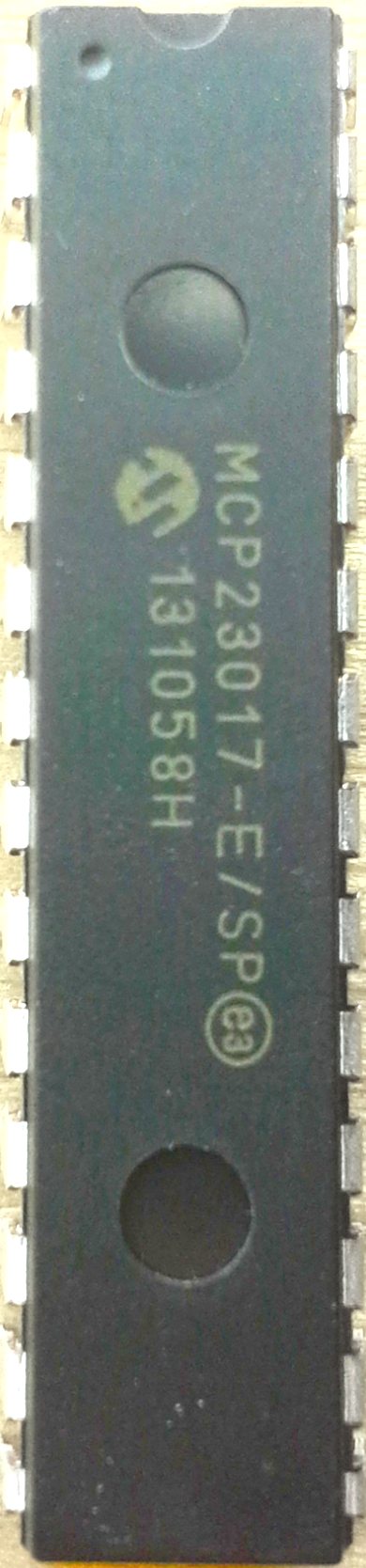 | 27 | ↔ | GPA6 |
| GPB2 | ↔ | 3 | 26 | ↔ | GPA5 | |
| GPB3 | ↔ | 4 | 25 | ↔ | GPA4 | |
| GPB4 | ↔ | 5 | 24 | ↔ | GPA3 | |
| GPB5 | ↔ | 6 | 23 | ↔ | GPA2 | |
| GPB6 | ↔ | 7 | 22 | ↔ | GPA1 | |
| GPB7 | ↔ | 8 | 21 | ↔ | GPA0 | |
| VIN | → | 9 | 20 | → | INTA | |
| GND | → | 10 | 19 | → | INTB | |
| 11 | 18 | ← | RESET | |||
| SCL | → | 12 | 17 | ← | ADDR2 | |
| SDA | ↔ | 13 | 16 | ← | ADDR1 | |
| 14 | 15 | ← | ADDR0 |
| SCL | ↔ | • 1 | ◡ | 18 | ← | VIN |
| SDA | ↔ | 2 | 17 | ↔ | GP7 | |
| ADDR2 | → | 3 | 16 | ↔ | GP6 | |
| ADDR1 | → | 4 | 15 | ↔ | GP5 | |
| ADDR0 | → | 5 | 14 | ↔ | GP4 | |
| RESET | → | 6 | 13 | ↔ | GP3 | |
| 7 | 12 | ↔ | GP2 | |||
| INT | ← | 8 | 11 | ↔ | GP1 | |
| GND | → | 9 | 10 | ↔ | GP0 |
*The bold pins are required. In particular, it is important to set the RESET pin to high.
GPA#, GPB#, GP# are the GPIO pins. On the 16 pin version, there are two ports denoted by the A and B (PORTA, PORTB).
INTA, INTB, INT are the interrupt outputs that can be monitored by the microcontroller to notify it when inputs change. On the 16 pin variant, there is one for each GPIO port.
| 0 | 1 | 0 | 0 | ADDR2 | ADDR1 | ADDR0 | Hex Addr. | Dec. Addr. |
| 0 | 1 | 0 | 0 | 0 | 0 | 0 | 0x20 | 32 |
| 0 | 1 | 0 | 0 | 0 | 0 | 1 | 0x21 | 33 |
| 0 | 1 | 0 | 0 | 0 | 1 | 0 | 0x22 | 34 |
| 0 | 1 | 0 | 0 | 0 | 1 | 1 | 0x23 | 35 |
| 0 | 1 | 0 | 0 | 1 | 0 | 0 | 0x24 | 36 |
| 0 | 1 | 0 | 0 | 1 | 0 | 1 | 0x25 | 37 |
| 0 | 1 | 0 | 0 | 1 | 1 | 0 | 0x26 | 38 |
| 0 | 1 | 0 | 0 | 1 | 1 | 1 | 0x27 | 39 |
The ADDR# pins can be set to high or low to change the address by 1 or 0 in the style in the address table allowing for a possible total of 8 different addresses, and therefore allowing up to 8 chips total. Both the 16 GPIO and 8 GPIO pin variants start at 0x20, so mixing the type will not help get more. If you are using more than 128 pins, you might want to consider alternatives like shift registers.
The RESET pin can be used to clear the registers and set it back to its power-on state, but really that isn't very useful since you can always use serail commands. So, usually you will just wire it directly to HIGH (3.3v or 5v) so that it always stay on.
Arduino
There is an Arduino library made available by adafruit on GitHub. Usage is very simple:
#include <Wire.h>
#include "Adafruit_MCP23017.h"

Adafruit_MCP23017 mcp;

# define BLINKPIN 0
# define INPUTPIN 1
# define ECHOPIN 13

// blinks MCP pin 0 on and off
// turns MCP pin 13 on when MCP pin 1 is high or unplugged

void setup() {
  mcp.begin();      // use default address 0x20 (0,0,0)

  mcp.pinMode(BLINKPIN, OUTPUT);

  mcp.pinMode(INPUTPIN, INPUT);
  mcp.pullUp(INPUTPIN, HIGH);  // turn on a 100K pullup internally
}

void loop() {
  delay(100);
  mcp.digitalWrite(BLINKPIN, HIGH);
  delay(100);
  mcp.digitalWrite(BLINKPIN, LOW);

  // ECHO only updates every 200 ms
  digitalWrite(ECHOPIN, mcp.digitalRead(INPUTPIN));
}
The major problem with the above code is that the ECHO is not updated until the delays are done. To get by that limitation, something like Metro or Kernel could be used, or simply checking the time yourself. This example was built just to show the bare minimum of how to interface with the MCP, not to show a practical application though.
Raspberry Pi
Adafruit also provies a Python library for the Raspberry Pi, which is also easy to use.
from Adafruit_MCP230XX import *

# Use busnum = 0 for older Raspberry Pi's (256MB)
# Use busnum = 1 for new Raspberry Pi's (512MB with mounting holes)
mcp = Adafruit_MCP230XX(busnum = 1, address = 0x20, num_gpios = 16)

# Set pins 0, 1 and 2 to output (you can set pins 0..15 this way)
mcp.config(0, mcp.OUTPUT)
mcp.config(1, mcp.OUTPUT)
mcp.config(2, mcp.OUTPUT)

# Set pin 3 to input with the pullup resistor enabled
mcp.pullup(3, 1)
# Read pin 3 and display the results
#bitshift output, third bit is the output
print "%d: %x" % (3, mcp.input(3) >> 3)

# Python speed test on output 0 toggling at max speed
while (True):
  mcp.output(0, 1)  # Pin 0 High
  mcp.output(0, 0)  # Pin 1 Low