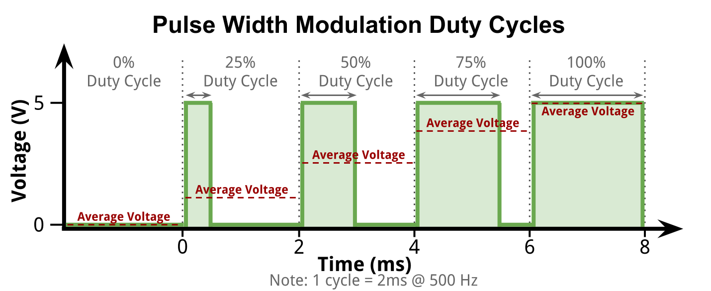
Pulse Width Modulation with analogWrite
Pulse Width Modulation with analogWritePulse Width Modulation (PWM) is used because a microcontroller cannot easily send a specific voltages. It really can only turn a switch on and off. To be able to send a ratio of the current voltage, something like a variable resistor would need to be digitally controlled, but we don't have that. Instead, what PWM does is essentially flip the switch really really fast. That way the average voltage can be varied by leaving the switch on for longer or shorter than it is off.
So, the average voltage is the percent duty cycle, multiplied by the "on" voltage.
Arduino Example
To get 2.5 average volts, just use a 50% duty cycle, since the Arduino outputs 5V normally.
However, the PWM function in arduino does not take duty cycle as a percentage. It takes it as a whole number out of 255. So, a 100% duty cycle would be 255. The 50% duty cycle would be 0.50 * 255 = 127.
Be sure to use a pin on the Arduino that has a ~ next to it, which represents that the pin can do PWM. Not all pins can. On an Arduino Uno, the available pins are 3, 5, 6, 9, 10, and 11. In this example, we will use 5 for no particular reason.
The resulting code to output 2.5 average volts will look like this:
analogWrite( 5, 127 ); // pin 5, half of 255 for 50%
