Blender Arduino Model
Blender Arduino Model
Results
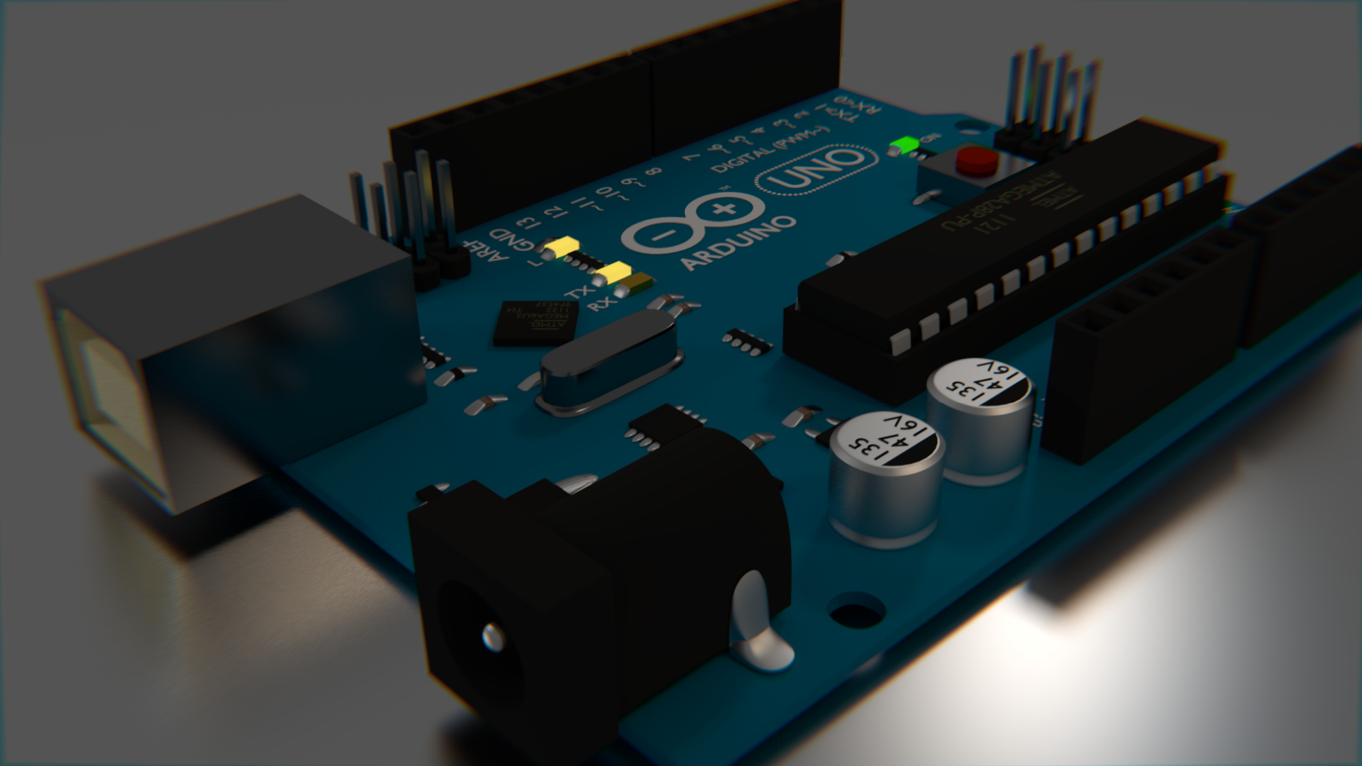
I could not really find any great Blender models of the Arduino Uno on the internet, so I decided to make my own. Mine was made entirely from scratch and does not use any image textures (except the wood in this demo). It features most of the details of the Uno, but does not have the printed circuitry. It was modelled off an image and some eyeballing for sizes, so it may not necessarily be to scale, but it looks close enough for Blender work. Even the text is there, using the default Blender font. The Arduino logo is actually a mesh of a circle. The most notable chips have the proper text on them, and the plugs even are shaped like sockets.

See the bottom of this post for the .blend files, or read more to see how it was done.
Progress
I kept renders from each of the steps along the way. I will describe each set of renders with a paragraph for each render in line from left to right.
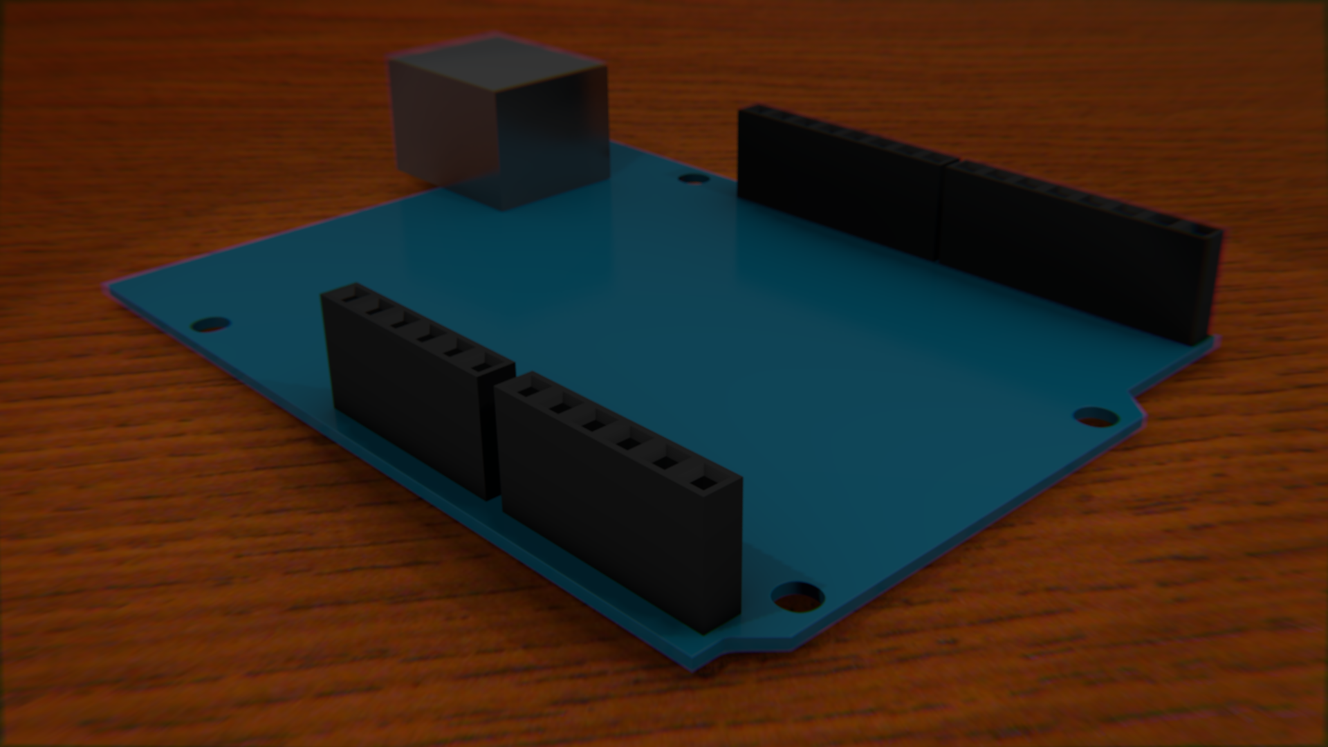
So, I start by tracing the board from an image, which was actually easy. Then "loop cut and slide" was done several times to square off the holes. Once the square holes are made, the subdivision modifier is applied. The edges on the top and bottom of the squares must be hardent with shift+e, otherwise it will look more like a worn down area than a drilled hole. The USB connection was easy. Picking the right material for it was the important part. It should be reflective and still have some roughness to it. Just one pin was made, then an array was used to duplicate the pin in a row. Then different sets were made by Shift+D for duplicate.
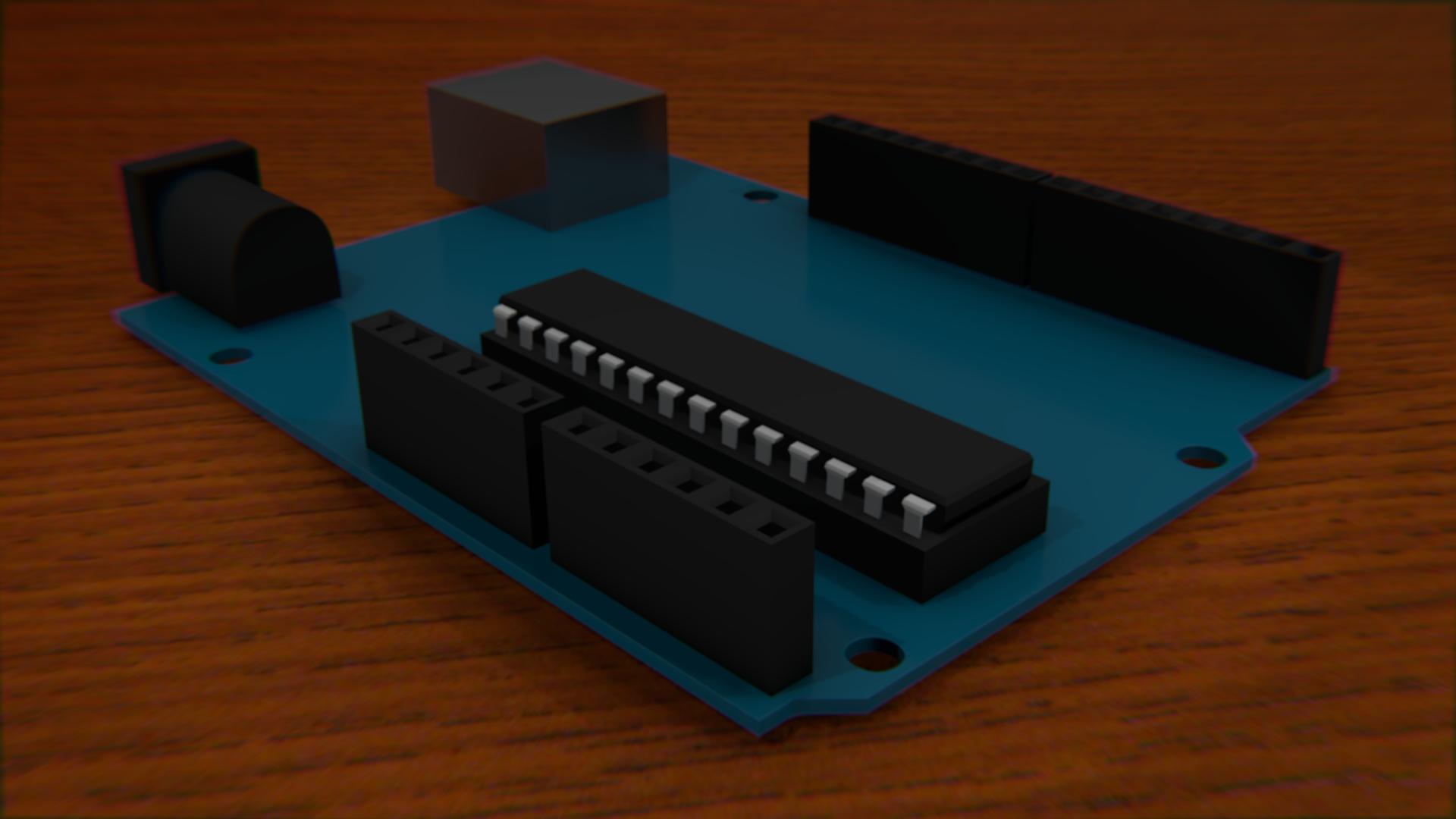
The power socket was easy, with just a cube. Extrude one face twice - once bigger then another the same size. Then subdivisions are applied to give the back end the rounded look. All edges but the top back two should be at their hardest with shift + e. The ATMEGA is actually really easy to do except for the pins, which never quite seem to look right.
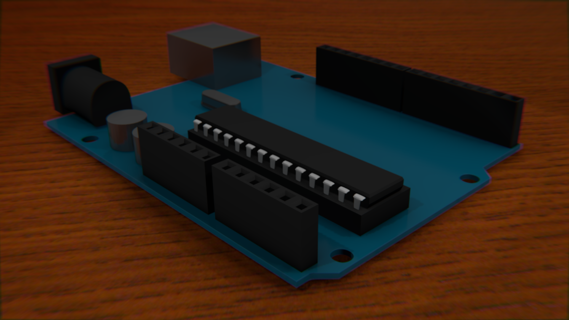
I started trying to add the capacitors and the piezo by using cylenders, but that was the wrong way to go about it. Subdivisions are a lot easier.
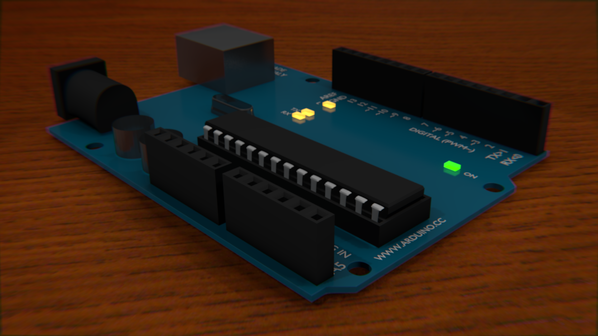
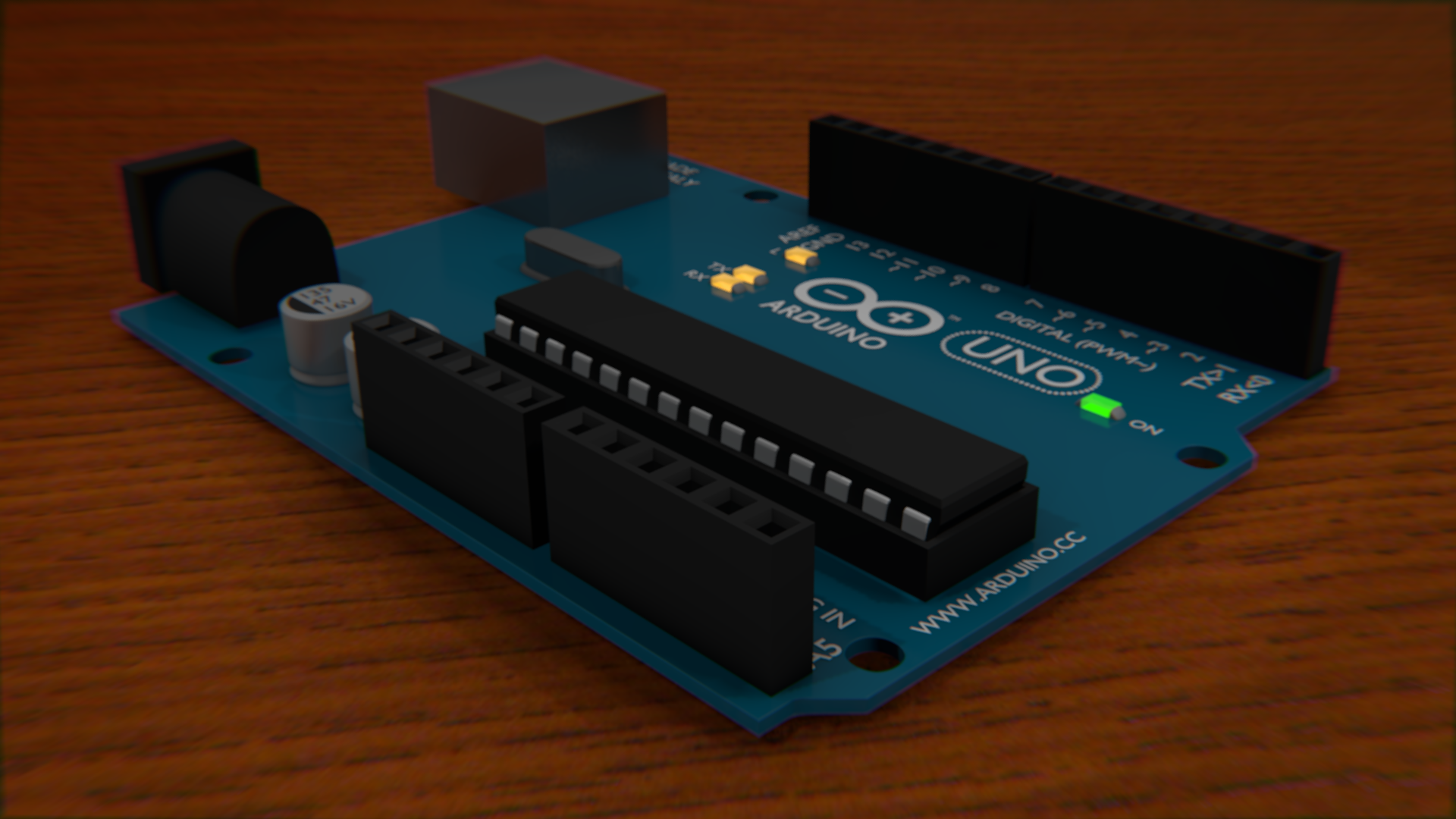
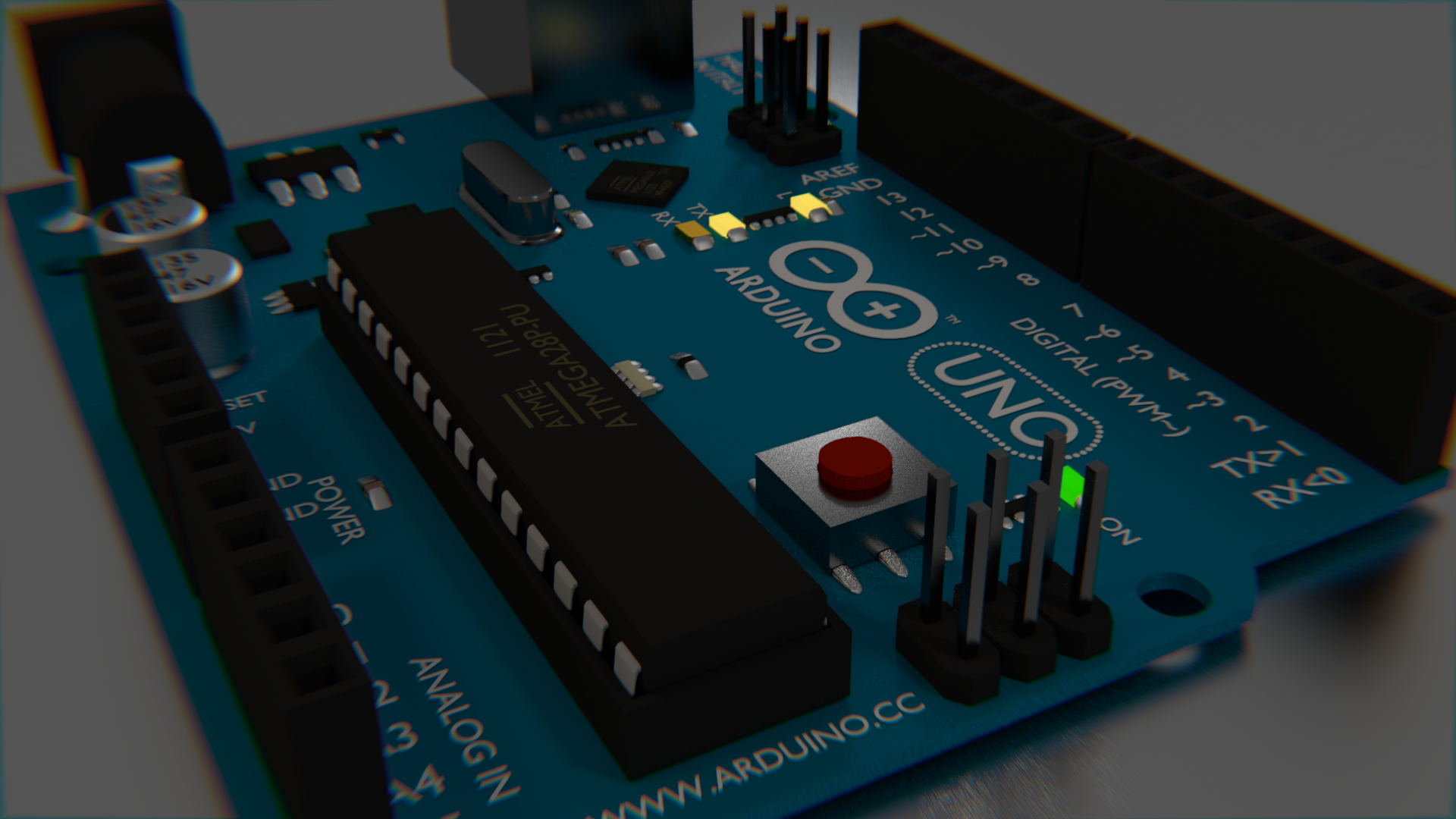
I realized that adding the text was going to be really important to making it look right. It was actually easy enough to add it in exactly the right places due to the use of a "background image" on the camera. When in wireframe mode, you can see both the text and the image you are tracing. The font is clearly wrong when looking at the comparison image, but it is not so obviously wrong when just looking at these images. The biggest difference is that the I is supposed to have the caps on it. The LEDs were added and turned on, just because they could be. It was later pointed out that it would be impossible for an arduino to have both on at the same time.
The arduino logo is simply a circle mesh extruded inward, then deformed a little bit. Here, I also fixed the capacitor and piezo to use subdivisions, and added the accurate notches and protrusions to each. I really like the way the black text on the capacitors looks. Again, the black side is just a circle.
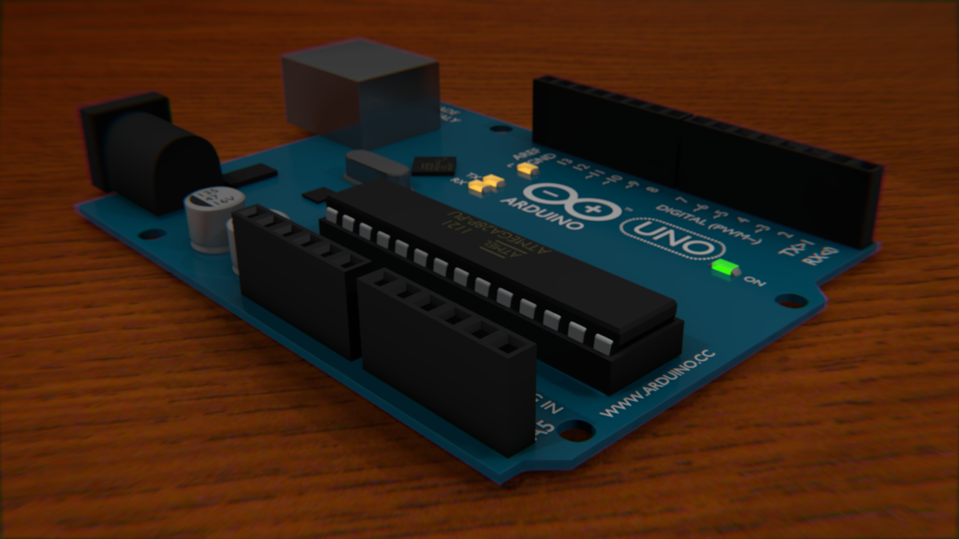


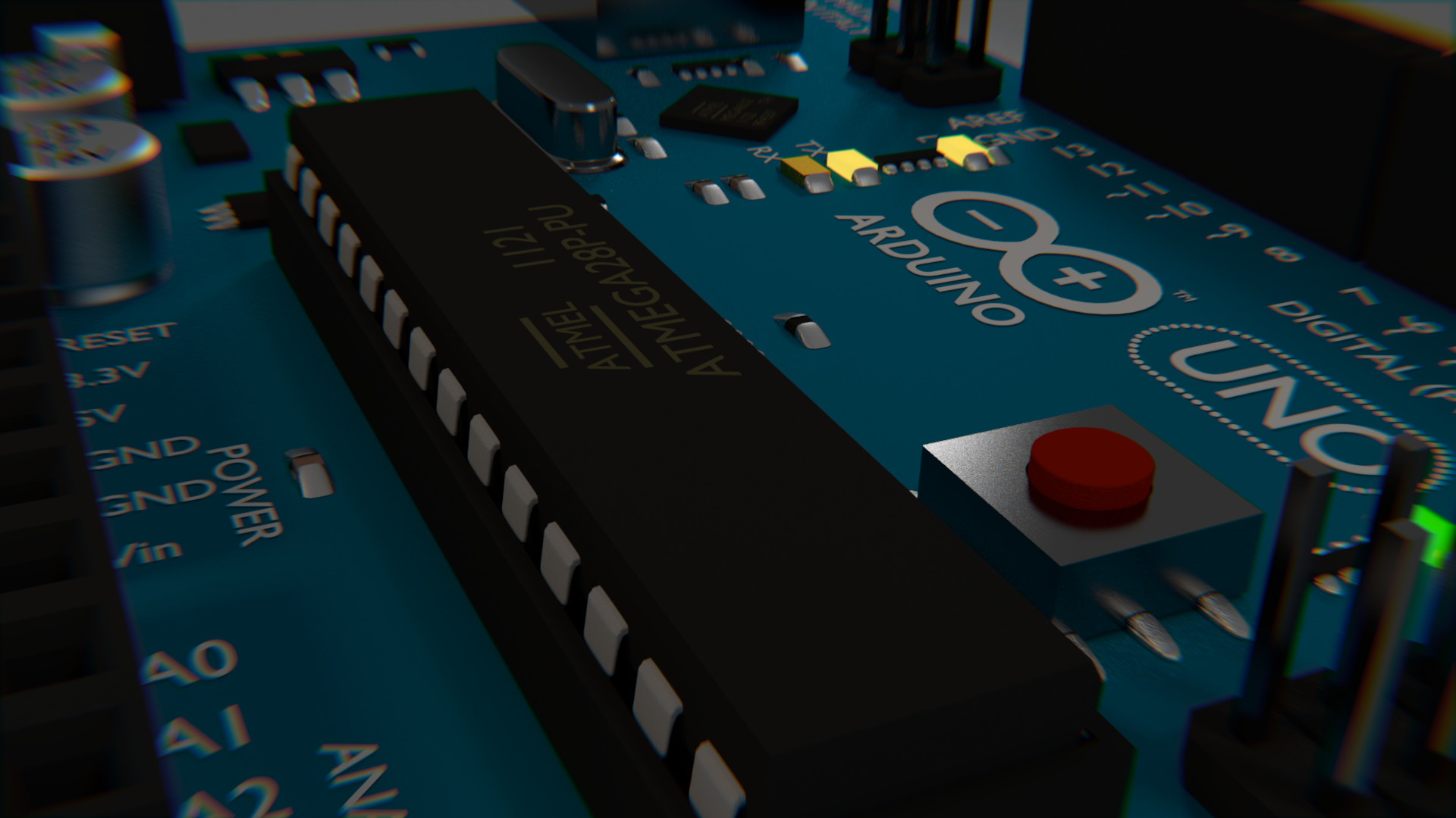
Of course the Arduino needs the text on the ATMEGA chip!. I also added some black boxes for the smaller chips that are scattered on the board. Here, a couple more black chips are being added to the board.
Here, I added the sockets to the USB and Power blocks. They did not have the interior parts before, but you couldn't see that. I still don't really like the way the interior of the USB socket looks, but I didn't really care as much about that feature.
I also wanted to add all of the little resistors and tiny components that litter the board, but decided to test how just this one works before duplicating it. I also tweaked the matte plastic texture a bit by making its specular less intense.
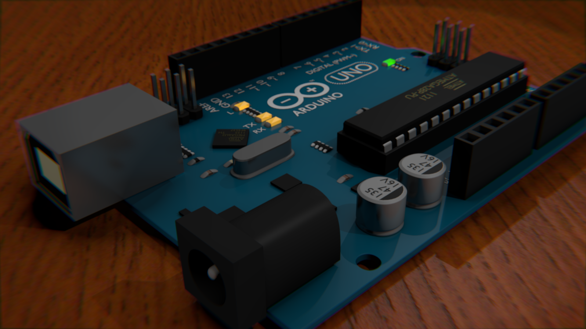
I then duplicated the resistors all over the place wherever they were needed. The pins that... well, actually I don't know what those ones that protrude do - I have never used them. Anyway, they were easy enough to make I didn't even use an array. I just duplicated them.
And of course, the reset button had to be added. That was just a box with a subdivided box on top. I also added connecting solder to a bunch of components. It's supposed to be mildly reflective, since it uses the same material as the capacitors, but it never really shows in these demos - probably because there is no skymap.
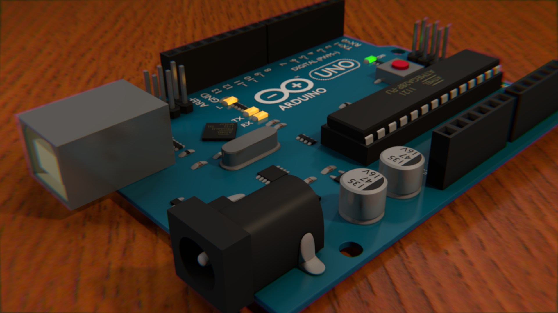
Cycles Tests
Cycles is a next-generation rendering engine in Blender. It is completely different than the current renderer, so the materials and textures system is entirely different and doesn't transfer back and forth. In theory, it is superior due to the fact that it all light bounces off things onto others. For example, if you have a light in your home that points upward toward the ceiling - as long as the ceiling is a light color it will still light the rest of the room since the light bounces off the ceiling too. The default blender render does not do this by default - but can be made to with the indirect lighting feature.
I struggled with the environment lighting in Cycles. The world material made a huge change in the overall lighting, and no matter what I tried nothing seemed to look quite right. However, the components themselves tended to have much better looks in cycles. I also decided to switch to a glossy demo surface just because It sort of looks nice with it's reflectivity. In some ways, these renders look nicer, and in some ways they look way worse.


Really, converting it to cycles was as simple as just enabling "use nodes" on all the materials and then changing it to glossy in most cases. Very little tweaking was needed with the exception of the LEDs, which needed to be emission types, but they didn't look quite right when they were just emitting, so I mixed an emission type with a regular one so that it was looked a little more in place.
I sort of wish that the LED's looked better than they do. They glow, but they don't really light up their surroundings as much as I would like, which is made extremely obvious by the dim environment lighting I settled with in cycles.