ArduIMU
ArduIMUIntroduction

An IMU is something used to detect primarily orientation, but is a general term for an Inertial Measurement Unit. Needless to say, they can provide some vital information for mobile robots. In particular, flying robots need them since there is no way to guess orientation using wheel encoders.
An advantage to having an all-in-one unit instead of just using each of its sensors yourself is that the board can cross-check and merge the data for you. For example, a gyro gives you changes in orientation in each axis, but an accelerometer and magnetometer both send 3D directions - both in different directions too. Furhtermore, the acceleration doesn't even always point down.
One would hope that these sensors would be able to give velocity or even position information. Sadly, the sensors are just not accurate enough to be able to numerically integrate and avoid drift error. It can be possible to use the information to refine something that is capable of giving position information - like a GPS. That is partly why many of these boards include a GPS port. The other is that they are primarily used in flying drones, which usually want a GPS anyway and it is not too expensive to add the connector.
Advantages
While maybe not the highest performance IMU, I picked this sensor because I found it reasonably cheap for $50 at DIY Robotics. I am now wondering if that was an error, since it is now more expensive. For $80, it is still an ok sensor. I also appreciate the fact that it can be reprogrammed with an FTDI cable and the Arduino IDE. This allows you to change settings and add your own features. Other IMU sensors will do this too, though. A very similar is the 130$ Razor IMU available from SparkFun.
Communication
Connection
Simply connect the RX to TX and TX to RX on each end of the ArduIMU and whatever you're reading it with.
To just read the output on a linux based controller, simply run the command in bash:
sudo cat /dev/ttyAMA0
Do not use I2C
Do not bother with trying to communicate with it via i2c. Sure, i2c is nice and compact, but the compass on the board is actually using those pins and i2c. As a result, the ArduIMU is in master mode, and you cannot be the master. I wasted a lot of time trying to figure out how to read it. Do not be fooled by the fact that you can see a device on the 1E address, that is the compass. Furthermore, i2c is a little too slow to be used, so even if that wasn't a problem, it would still be a bad idea.
Format
According to the Google Code page, the output format is like this:
!!!VER:1.8.1,RLL:1.12,PCH:-0.07,YAW:34.03,IMUH:253,LAT:499247361,LON:-1193955623, ALT:3525,COG:0,SOG:0,FIX:1,SAT:9,TOW:21230400***
That's probably not what yours looks like though. To see where this comes from, find the source code here for your version, then look at Output.pde. In my version 1.9.1, the format adds slots for analog pins. My ArduIMU v3 outputs something in the format of:
Temp: 63503 Accels: 0 2 27 Gyros: 0 0 0 Mag: 397 0 -482
First of all, those spaces are actually tab characters. Also I have no idea what temp is doing, but it looks useless here since it is just changing randomly. "Gyros" is the change in orientation detected by the gyroscope. So it will say 1 or -1 usually in each - maybe a little more if it's turning fast. The accels and mag outputs are vectors pointing in the direction and magnitude of the pull in x,y, and z. The default output lacks any euler angles, quaternions, or direction cosine matrices which is disappointing.
In all likelihood, the ArduIMU is probably sending you more information than you really want. It may be worthwhile to reprogram it to give you only the information you need. Most of the common choices can be made by editing Arduimu.ino.
After some tweaking, mine now looks like this:
RLL:-7.76,PCH:3.77,YAW:145.72,IMUH:253,ACCX:-0.33,ACCY:-0.67,ACCZ:9.58,
It prints the euler angles, IMU health, and acceleration vector. I also removed anything to do with a GPS. It's fast enough that the Arduino IDE can't keep up with the serial output. It maxes out my processor and lags behind a bit. Hopefully this is not the sensor lagging, but just the extremely rapid displaying.
If you are interested, read how to program the ArduIMU below, then grab my modifications to the stock ArduIMU code at the bottom of this page.
Reprogramming
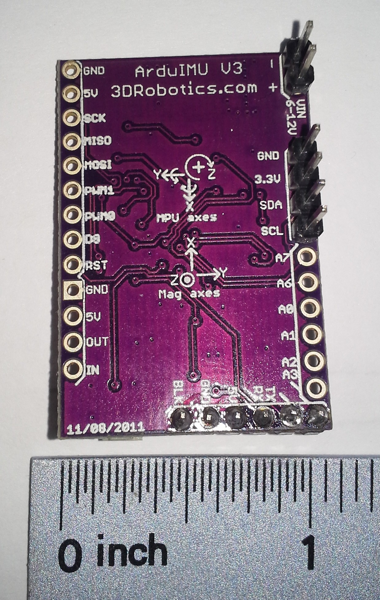
Wiring the FTDI
| ArduIMU v3 | OSEPP FTDI |
| BLK | GND |
| GND | CTS |
| 5V | VCC |
| RX | TXD |
| TX | RXD |
| ??? | DTR |
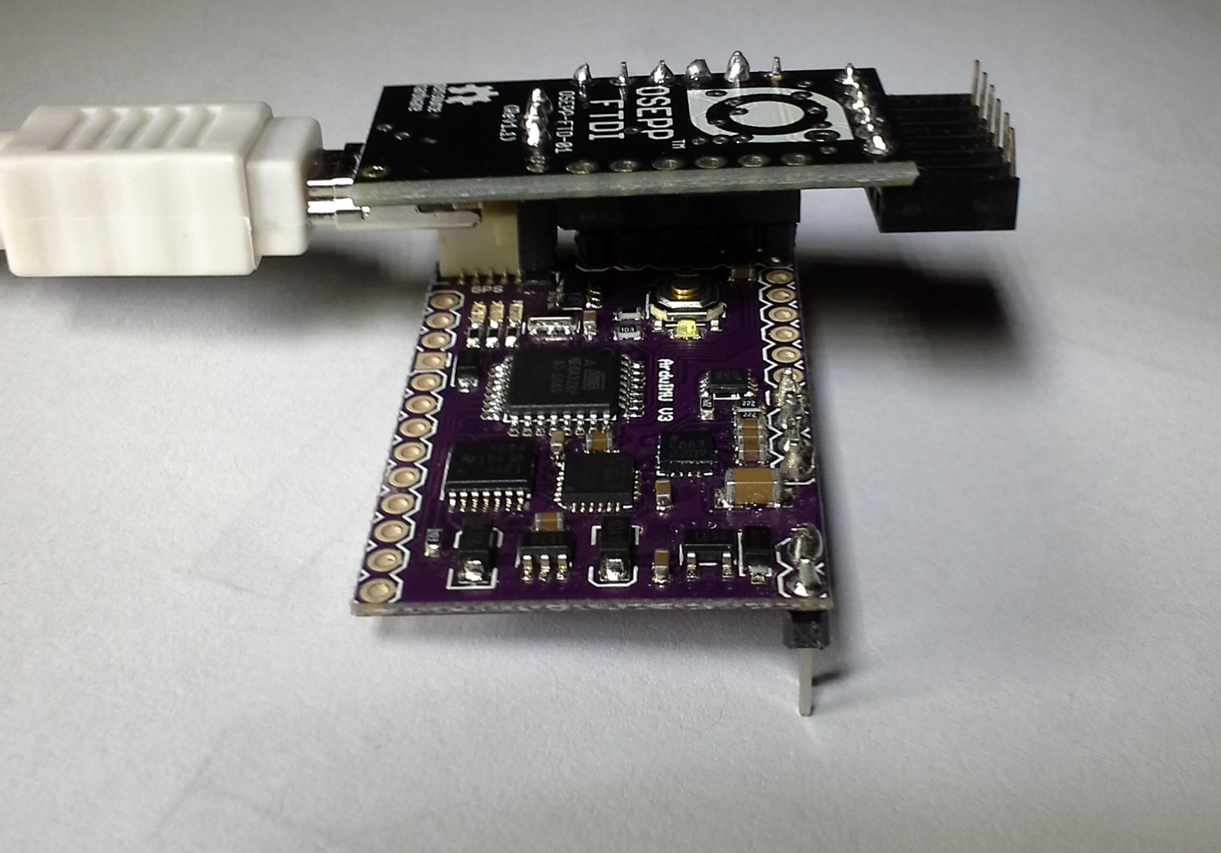
Odds are you really want the Euler angles, quaternion, or rotation matrix to be printed, since that is a lot easier to use quickly. You will need an FTDI cable. I picked the OSEPP one because it has a jumper to choose between 3.3V and 5V, which seems like an awesome feature. I picked that up for around 15$ on Amazon.
I was able to just solder some female header onto my OSEPP FTDI and plug the Arduimu in directly using the group of horizontal pins at the bottom. Also be sure to switch it to 3.3V mode. From what I've read, it seems like it may not matter, really, what the voltage is on some of the lines. SparkFun discuses it on one of their product pages. I'm betting there is some truth to that since there is a 5V pin.
Also, depending on the FTDI cable you have, there is a possibility that you might need to press the reset button yourself. The auto-reset feature is apparently somewhat new and will also depend on whether it is wired up correctly.
It is also recommended that you power the ArduIMU with something other than the FTDI cable while programming. So, be sure to connect an additional power source to the Vin or 3.3V pins.
Makefile
From there, you just need to configure the makefile. Run make configure to configure make, then run make upload to compile and upload it. My Makefile looked like this, but I never actually got it to work:
BOARD	=	atmega328
ARDUINO_DIR  = /usr/share/arduino
TARGET = Arduimu
ARDUINO_PORT = /dev/ttyUSB0
ARDUINO_DIR  = /usr/share/arduino
AVR_TOOLS_PATH = /usr/bin
include ../AP_Common/Arduino.mk
I also found that you might need to add #define ARDUINO 103 to the code in order to fix a few compile errors. This was probably a sign of some bigger problems though.
Arduino IDE
It is actually easier to just use the Arduino IDE.
Copy the Library folder from the zip of the code you download to your sketchbook Library folder.
Open the Arduimu.ino file in the Arduino IDE.
Simply select the correct Serial port - on my Ubuntu Linux system it was /dev/ttyUSB0. Then select a compatible board - the Arduino Nano w ATmega328. The programmer is just the standard AVRISP mkII due to the serial interface selected. On windows, the setup process for the FTDI cable may be more in depth. The ArduIMU google code page has some more information on it. You might be better off just looking up your specific FTDI cable first though.
With the FTDI cable on my system, you can actually just open the serial monitor and set the baud rate to 38400. I didn't know that at first and was hooking it up to a raspberry pi to see the output. This is a lot easier.
Fixing Bugs
If you get this error:
AP_Common/AP_Common.h: In function ‘int strcasecmp_P(const char*, const prog_char_t*)’:
AP_Common/AP_Common.h:108:38: error: ISO C++ forbids declaration of ‘type name’ with no type [-fpermissive]
AP_Common/AP_Common.h:108:38: error: ISO C++ forbids declaration of ‘type name’ with no type [-fpermissive]
AP_Common/AP_Common.h:108:32: error: expected primary-expression before ‘const’
AP_Common/AP_Common.h:108:32: error: expected ‘)’ before ‘const’
Just add this line to the top of Arduimu.pde. Somewhere above the #include statements:
typedef char PROGMEM prog_char;
I also went around and removed FastSerial and just left it with the regular serial. I'm guessing there was a good reason for making their own, but it was extremely annoying that they had to use the same variable name as the regular Serial object. I couldn't get it to compile due to it.
Configuring Output
There are a bunch of #define statements in the Arduimu.ino file. Those can be changed to modify a lot of the important features. I had to change just about every one of the settings to get what I wanted. This is the result:
// Enable Air Start uses Remove Before Fly flag - connection to pin 6 on ArduPilot
#define ENABLE_AIR_START 0  //  1 if using airstart/groundstart signaling, 0 if not
#define GROUNDSTART_PIN 8    //  Pin number used for ground start signal (recommend 10 on v1 and 8 on v2 hardware)

/*Min Speed Filter for Yaw drift Correction*/
#define SPEEDFILT 0 // >1 use min speed filter for yaw drift cancellation (m/s), 0=do not use speed filter

/*For debugging propurses*/
#define PRINT_DEBUG 0   //Will print Debug messages

//OUTPUTMODE=1 will print the corrected data, 0 will print uncorrected data of the gyros (with drift), 2 will print accelerometer only data
#define OUTPUTMODE 1

#define PRINT_DCM 0     //Will print the whole direction cosine matrix
#define PRINT_ANALOGS 0 //Will print the analog raw data
#define PRINT_EULER 1   //Will print the Euler angles Roll, Pitch and Yaw
#define PRINT_GPS 0     //Will print GPS data
#define PRINT_MAGNETOMETER 0     //Will print Magnetometer data (if magnetometer is enabled)

// *** NOTE!   To use ArduIMU with ArduPilot you must select binary output messages (change to 1 here)
#define PRINT_BINARY 0  //Will print binary message and suppress ASCII messages (above)

// *** NOTE!   Performance reporting is only supported for Ublox.  Set to 0 for others
#define PERFORMANCE_REPORTING 0  //Will include performance reports in the binary output ~ 1/2 min
Furthermore, I think it is weird that they would have an option to print the magnetometer, but not the accelerometer. It seems like acceleration would be a lot more important for a controller, since the magnetometer's information, I assume, is already built into the orientation output.
Modifying the Output
To add the acceleration information, I just modified Output.ino (line 61 to 68)
#define ACCELCONVERSION 0.0023147712
Serial.print("ACCX:");
Serial.print(Accel_Vector[0]*ACCELCONVERSION);
Serial.print(",ACCY:");
Serial.print(Accel_Vector[1]*ACCELCONVERSION);
Serial.print(",ACCZ:");
Serial.print(Accel_Vector[2]*ACCELCONVERSION);
Serial.print(",");
The ACCELCONVERSION constant was chosen by expermentation to convert to the output to m/s2 using the following method:
- Print the values of the Accel_Vector
- Leave the ArduIMU on a flat level surface
- Take a few samples of the acceleration on the z axis (Accel_Vector[2])
- ACCELCONVERSION = 9.81 / SampleAverage
Repeat the process, if necessary, until the output is correctly calibrated to the known gravitational constant.
It is perhaps better practice to instead do the conversion on the recieving device, since the values would be more compact and accurately sent over serial. On the other hand, it makes the ArduIMU more easily accessible if the units are known. To convert the acceleration data on the reading device, the proceedure is the same.
Parsing the Serial Input
While you could read this sensor with an Arduino, it already is an Arduino. Furthermore, the mere fact that you're using it probably means you want to analyze a 3D system. You're probably going to need some more firepower. Something like a Raspberry Pi, or a BeagleBone. A Raspberry Pi processor is at least 1000 times faster than an Arduino, and a BeagleBone Black is at least twice as fast as a Raspberry Pi and has more pins.
With these faster devices, you get to use a higher level programming language like Python or Node.js. Both will run Python, so it is a good choice for speed and portability.