Clock Display Without Serial
Clock Display Without SerialIntroduction
This is a tutorial on how to build a clock display using only an Arduino, a Shift Register, and 4 digit seven segment display.
The end result should look something like this mess:
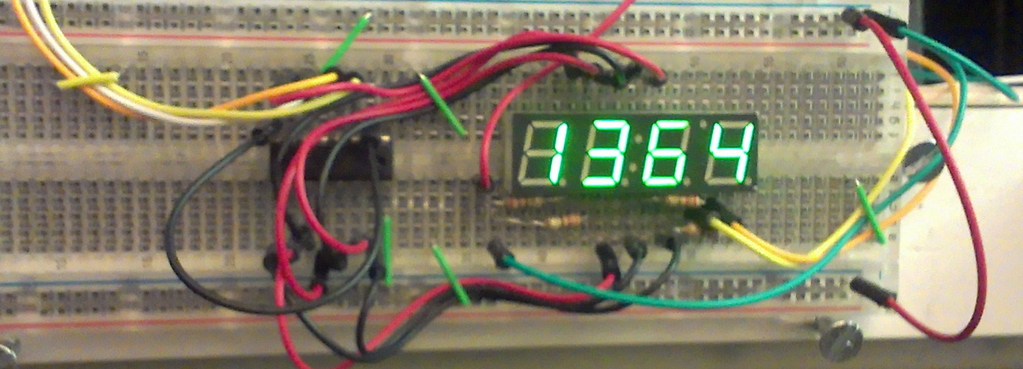
In this image, you can see an accelerometer to the left, which is not a part of this tutorial.
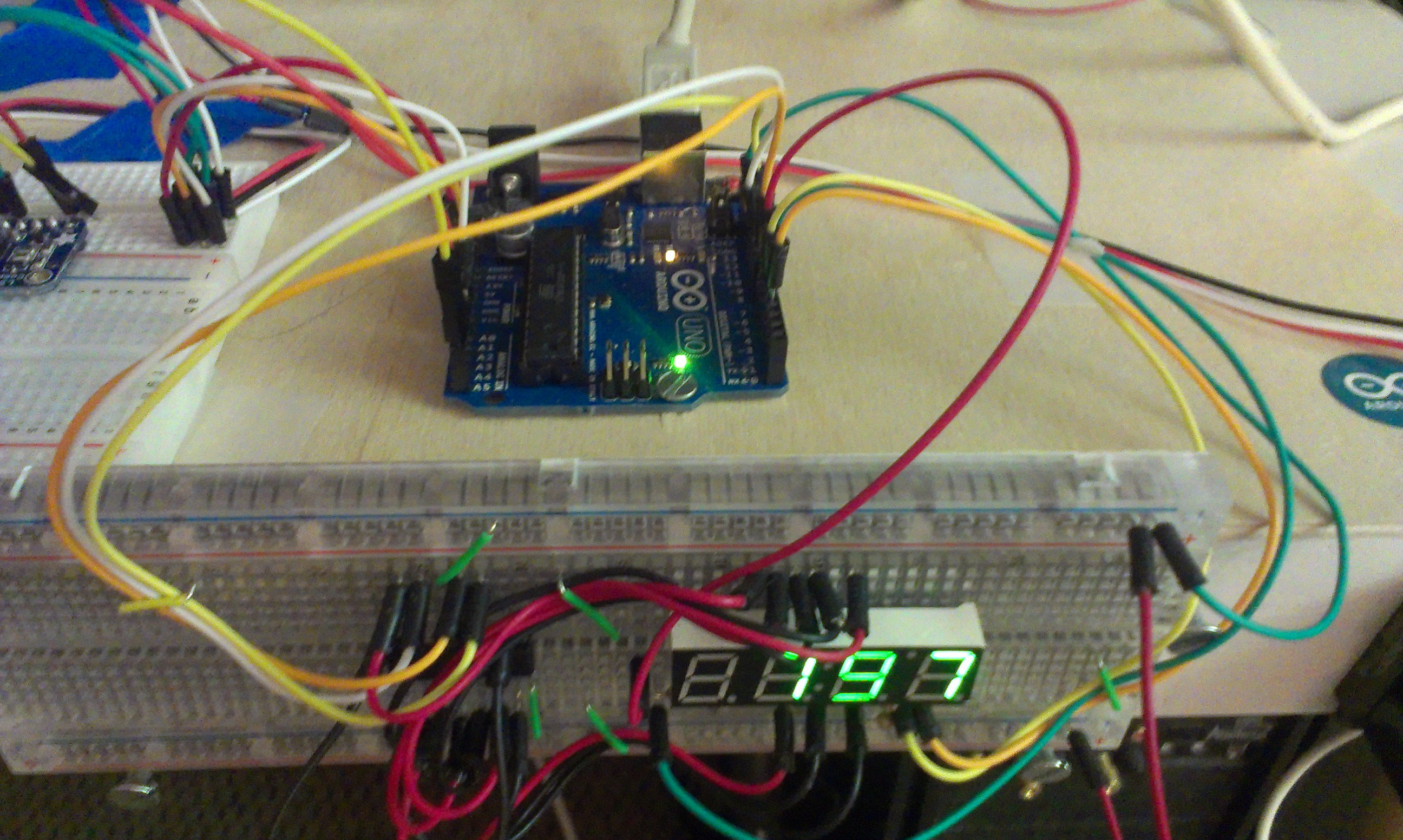
Clearly, the whole thing gets very messy. As a result, I would recommend one that works by serial, offloading this wiring and refreshing. There is a great Arduino-based one by Sparkfun , and a cheaper one available at Adafruit . It's $10-$13 for the serial ones, but these bare displays are 2$, the shift register is 3$ for a pack of three, uses at about 20 breadboard wires, 8 pins on your Arduino, and requires that the Arduino be able to cycle through the digits of the display frequently. The extra cost is minimal and saves a lot of effort.
Parts List
- .39 inch 4 digit 7 segment display (BL-Q39A-42UG-21 from Adafruit )
- 74HC595 Shift Register (bought from Adafruit )
- Arduino Uno
- 4x 220Ω resistors
- Lots of breadoard wire
Pinout of Display
I had some trouble getting the display to work according to the spec sheet, so I just reverse engineered it.
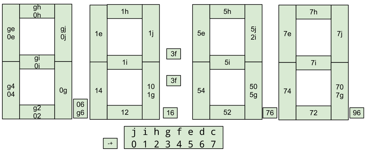
The numbers on the digit segments are in the order of negative and positive. So, to light up the left most digit, 0 must be negative (grounded), and each of the segments can be lit with by giving each of the right most lettered pins a positive. As a result, the grounding pin must be cycled, and the other digits must be positive. Also, apparently the 0 and g pins are interchangable.
Wiring Diagram
I made a wiring diagram in Fritzing. Even like this, it still looks daunting, but at least you can tell what goes where.
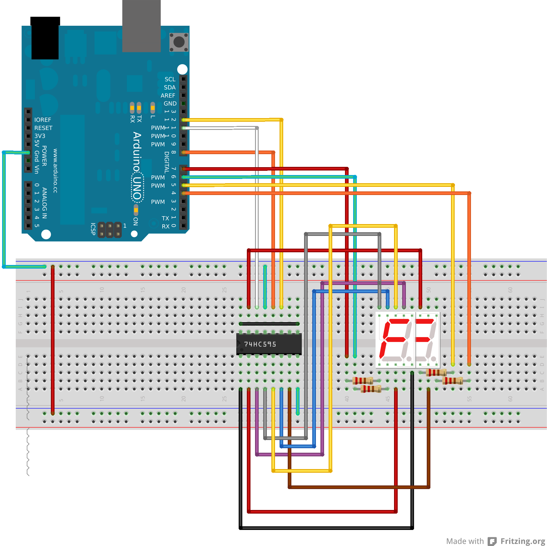
I couldn't find something for a 4 digit seven segment display that has 8 pins on each side. So, I just used two 7 segment displays overlayed so they had the right number of pins. It looks ugly, but pretend it's ok. The wires should still be the same.
The svg and Fritzing files are attached at the bottom as well for your convenience.
Code
The code is also somewhat complicated. There are two main problems: converting a character to a a map of on or off values for each pin, and the fact that the display has to be refreshed ever few milliseconds. I took care of both problems by writting my own class. It should actually be universal for all 7 segment displays with minimal adjustment. I wrote it to utilize the Kernel library I made so that the timing is non-blocking.
The .ino file:
#include "kernel.h"    //handles timing in non-blocking way
#include "SevenSeg.h"  //maps characters to pin outs on shift register

// declare some global instances of the classes
Kernel kernel;
SevenSeg sev;


int count = 0;
void increment() {
    sev.display( count );
    count++;
    if ( count > 9999 ) {
        count = 0;
    }
}


void setup() {
    //set up the seven segment display class
    sev.setup();
    sev.setShift( 8, 12, 11);  //which pins the
    sev.setDigits( 7,6,5,4 );
    sev.setSegmap( 0, 1, 2, 3, 4, 5, 6, 7);

    //takes an Unsigned Long (UL) for the microseconds between intervals
    kernel.setInterval(100000UL, increment);
}

void loop() {
    kernel.runNext();
}
The SevenSeg.h class:
The SevenSeg class should be universal, but you have to do a few things to set it up first.
First, you need to tell it which pins the shift register is on. This is fairly straightforward with:
setShift(latch, clock, data)
The arguments should correspond to the spec sheet for your shift register
- latch: may be denoted as ST_CP, or RCLK
- clock: may be denoted as SH_CP, or SRCLK
- data: may be denoted as DS, or SER
Next, you need to tell SevenSeg which pins are used to toggle which digit is being lit in the cycle. These should be real pins on the Arduino addressable by digitalWrite. The digits are in order from left to right.
setDigits( 7,6,5,4 );
Then, you need to map the digits of the display to the pins on the shift register
setSegmap( ... )
The value of the argument is the pin on the shift register. The order of the arguments says which segment it belongs to according to this:
/*
  0 5555555555555 4
  00 55555555555 44
  00             44
  00             44
  00             44
  00             44
  0 6666666666666 4
  1 6666666666666 3
  11             33
  11             33
  11             33
  11             33
  11 22222222222 33   777
  1 2222222222222 3   777
*/
Conclusion
Download the Arduino code: ![]() sevSegTest.zip
sevSegTest.zip
Again. It's a really really good idea to just get one that works over serial.