Learn
LearnPraface
These are some lessons, projects, and code we have made and decided to share with the world. We like to document our work so we can come back to it later, but hopefully others find it useful too! If you would like to see some other topics, feel free to contact us.
Using the Website
Below is a tree of all topics, lessons, and content. You can also print the whole thing at once!
There is also a tag cloud over at the right.
Arduino
ArduinoPreface
Arduino is an awesome way to get into robotics. It is a very easy to use microcontroller that you program in C/C++. It does analog digital on/off input and output, reading of voltages, anolog output by Pulse Width Modulation (PWM) which is useful for hooking up motors, serial communication which is useful for communicating with sensors and other external devices.
A simple Arduino program example is blinking an LED. The code looks like this:
int led = 13; // Pin 13 has an LED connected on most Arduino boards.

void setup() {               // the setup routine runs once when you press reset:
  pinMode(led, OUTPUT);      // initialize the digital pin as an output.
}

void loop() {                // the loop routine runs over and over again forever:
  digitalWrite(led, HIGH);   // turn the LED on (HIGH is the voltage level)
  delay(1000);               // wait for a second
  digitalWrite(led, LOW);    // turn the LED off by making the voltage LOW
  delay(1000);               // wait for a second
}
Not too hard, right? We have lots of tutorials on how to do more advanced things with your Arduino.
Pulse Width Modulation with analogWrite
Pulse Width Modulation with analogWritePulse Width Modulation (PWM) is used because a microcontroller cannot easily send a specific voltages. It really can only turn a switch on and off. To be able to send a ratio of the current voltage, something like a variable resistor would need to be digitally controlled, but we don't have that. Instead, what PWM does is essentially flip the switch really really fast. That way the average voltage can be varied by leaving the switch on for longer or shorter than it is off.

So, the average voltage is the percent duty cycle, multiplied by the "on" voltage.
Arduino Example
To get 2.5 average volts, just use a 50% duty cycle, since the Arduino outputs 5V normally.
However, the PWM function in arduino does not take duty cycle as a percentage. It takes it as a whole number out of 255. So, a 100% duty cycle would be 255. The 50% duty cycle would be 0.50 * 255 = 127.
Be sure to use a pin on the Arduino that has a ~ next to it, which represents that the pin can do PWM. Not all pins can. On an Arduino Uno, the available pins are 3, 5, 6, 9, 10, and 11. In this example, we will use 5 for no particular reason.
The resulting code to output 2.5 average volts will look like this:
analogWrite( 5, 127 ); // pin 5, half of 255 for 50%
Reading Numbers From Serial
Reading Numbers From SerialIntroduction
Reading numbers from serial on an Arduino is needed surprisingly commonly. Exactly what is happening might be kind of hard to figure out.
Serial
Serial communication is digital, which means all data is transmitted in 1's and 0's. Typically, serial communication is done using ASCII letters. This means that, to send a number to the Arduino, the data sent is not the binary version of the number in base 2 (as an integer), but instead a sequence of characters for each digit in base 10 (which is human-readable). It is not an efficient use of bandwidth, but bandwidth is not usually a problem with Arduinos connect by USB.
Arduino Code
char commandLetter;  // the delineator / command chooser
char numStr[4];      // the number characters and null
long speed;          // the number stored as a long integer

void serialEvent() {
  // Parse the string input once enough characters are available
  if(Serial.available() >= 4) {
    commandLetter = Serial.read();

    //dump the buffer if the first character was not a letter
    if ( ! isalpha( commandLetter ) {
      // dump until a letter is found or nothing remains
      while(( ! isalpha( Serial.peak() ) && Serial.available()) {
        Serial.read(); // throw out the letter
      }

      //not enough letters left, quit
      if ( Serial.available() < 3 ) {
        return;
      }
    }

    // read the characters from the buffer into a character array
    for( int i = 0; i < 3; ++i ) {
      numStr[i] = Serial.read();
    }

    //terminate the string with a null prevents atol reading too far
    numStr[i] = '\0';

    //read character array until non-number, convert to long int
    speed = atol(numStr);
    Serial.println(speed);
  }
}
Code Explanation
serialEvent
serialEvent is a function that is called by Arduino before each loop. So, you can separate out your serial handling from the rest of your code. You could also put the contents of this function in the loop() function and it would be similar.
Fixed-Width
Commands need to be delineated in some way. Fixed-width commands are convenient on Arduino because the Serial.available function tells you how many characters are waiting. It is also possible to delineate by special characters. An extremely common and simple version of this is a Comma Separated Value file. However, since it is simplest to use C strings, the character arrays which the serial is read into is necessarily fixed-width anyway. To get around this issue, a vector or linked list could be used, so the serial string can dynamically grow and shrink.
Command Differentiation
In many cases, a robot takes multiple kinds of inputs. For example, there might be multiple speeds, or a direction, or some kind of trigger. Prefixing each command with a unique letter can make it easy to differentiate what the following string is supposed to do.
C Strings
C strings are arrays of char data types. They must be terminated by a NULL character '\textbackslash 0'. Without the NULL character at the end, there is no way for any function to know how long the string is. For example, a print function would print the string and then a bunch of garbage characters until it gets to a NULL or the end of the memory available. In this case, it's less likely for that to happen since we are only using atol, which will only read until there is a non-numeric character. A non-numeric byte is more likely to randomly be at the end of the string than a NULL character.
| Decimal | Character |
| 48 | '0' |
| 49 | '1' |
| 50 | '2' |
| 51 | '3' |
| 52 | '4' |
| 53 | '5' |
| 54 | '6' |
| 55 | '7' |
| 56 | '8' |
| 57 | '9' |
Char to Integer
Converting a single character to a number takes advantage of how characters are stored, which is typically in a format called ASCII. Think of a char of ASCII like an integer data type. Except that when printed, it is not a decimal number. The number in the int is translated into a letter on the screen according to a table. For example, the decimal number 97 is translated into the letter 'a'. Each letter is really stored as a 'number'. I'm showing it as a decimal (base 10) number, but it is really stored in binary (base 2). The C++ compile takes care of translating our base 10 decimal numbers into base 2 binary.
Here is how to take advantage of this:
int number = (int)charInput - (int)48;
// or:
int number = charInput - '0';
Since ASCII stores the letters sequentially, starting at 0, just subtract the value where 0 begins from each of the characters to convert it to its numeric form. This works regardless of the base of the character storage. So, it converts the ASCII character representing the number in base 10 into an integer in base 2.
Char Array (C-string) to Long Integer
Now, each of the letters from right to left need to be multiplied by a power of 10. Here is the basic idea of what atol does:
char charArray[5] = "5432"; // double quotes adds the \0 at the end

long longnum = 0;  //the converted number
long exp = 1;      //start with 10^0
int index = 0;     //the current place in the array

//find the end of the string - when character is not a number
while ( isdigit( charArray[idx] ) ) {
    ++idx;
}

//begin base multiplication and number conversion
while( idx >= 0 ) {
    //convert digit character to a long
    long currentDigit = (long) charArray[idx] - (long)48

    currentDigit *= exponent; //number multiplied by 10^(len-idx)
    exponent *= 10; // next number to left is another power of ten

    longnum += currentDigit;

    --idx;
}
Serial Commands
Serial CommandsIntroduction
Serial communication through USB can be used to communicate between a host computer (like a laptop, or Raspberry Pi), and an Arduino. Doing so allows:
- Use of the faster hardware of the host computer for calculations
- Synchronization of multiple Arduinos
- Use of other information provided by the host computer, like internet connections or larger data files
- Creation of a graphical interface using the host's display or web server
Communication
Communication is easy. Arduino and Python have simple methods for establishing serial communication.
Arduino
void setup() {
    Serial.begin(9600); //Initialize serial communication at 9600 baud
}
void loop() {
    Serial.println('hello');
}
Python
from serial import *
ser = Serial( "/dev/ttyACM0" , 9600 )

while 1:
    print ser.readline()
Incomplete Messages
One of the most difficult issues with this sort of serial communication is ensuring that commands are received in entirety. If you send "1000" from Python, and want Arduino to read it as shown below, Arduino might read "10" and then in another loop() right afterward read "00".
char incoming[11] = "          ";
int i = 0;
while (Serial.available() > 0) {
    // read the incoming byte:
    char[i] = Serial.read();
    i++;
}
//Convert the incoming string into an integer!
int newNumber = atoi(incoming);
Fixed Length Packets
One way to solve this in an efficient manner is to use a fixed length for commands and wait until there are enough bytes waiting in the buffer. The downside is that no commands may be issued with a length longer than the fixed length, and requires remaining length be wasted.
Python
ser.write('%10d' % 1000 ) #pad the number so it is 10 characters long
Now just add a condition so that no reading is done unless a full command is waiting in the serial buffer.
Arduino
if ( Serial.available() >= 10 ) {
    char incoming[11] = "          ";
    int i = 0;
    while (Serial.available() > 0) {
        // read the incoming byte:
        char[i] = Serial.read();
        i++;
    }
    //Convert the incoming string into an integer!
    newNumber = atoi(incoming);
}
Delineation
Another way to solve this problem is to delineate commands by placing a special character at the end of each command to signify that the command is complete. The problem with this way is that the length of the incoming string is unknown, and a long or improperly formed command could overflow a fixed length array. To overcome this limitation, a dynamic class is usually used. The String object is a good solution as it can be easily converted back into a character array. Maintaining data types with C++ strings can quickly become confusing, and it is extremely important that the delineation character is never used in the command. There are some special command characters in ASCII that would be good choices.
Multiple Command Types
You can send different commands over the same communication line by attaching a prefix to the command. For example, speed and position could be sent as "p000001000" and "s000000200" to tell the Arduino to go to position 1000 at a speed of 200.
Python
ser.write('p%9d' % 1000 ) #send position, padded to 9 (plus 1 command char)
ser.write('s%9d' % 200 )  #send speed, padded to 9 (plus 1 command char)
Arduino
int position, speed;
if ( Serial.available() >= 10 ) {
    //read the first character as the command
    char command = Serial.read();

    char incoming[10] = "         ";
    int i = 0;
    // read the incoming byte:
        char[i] = Serial.read();
        i++;
    }
    //Convert the incoming string into an integer, based on command
    if ( command == 'p' ) {
        position = atoi(incoming);
    }
    else if ( command == 's' ) {
        speed = atoi(incoming);
    }
    else {
        //The command was not one of the recognized characters
        Serial.println("COMMAND ERROR - Not recognized");
    }
}
Now that your communication is established, it is up to you to figure out what to do with the data on either end.
Splitting a String
Splitting a StringIntroduction
There are times when a string is recieved, but rather than the entire string, just a piece of the string is desired. Unfortunately, there does not appear to be a simple way to handle strings in C++. Therefore, I have devised a way to split a string based on comma separation.
This way of splitting strings is rather crude and refinement for it will be worked on, but for immediate use, the current function is given with two examples of how it can be altered and used.
Coding
Splitting Strings - Two Characters
This code was used in a project that controlled a robot via computer. The computer sent data through an XBee to an Arduino that served as the brains. That Arduino would get the string from the computer, pick it apart and find the important information. That information was then relayed to an Arduino that controlled the robot's motors. The single character that was sent to the motor Arduino then told which direction to move the robot in.
//Brain Code

char string[25];
char id[2];
char direct[2];


int ii=0;

void setup() {
  Serial.begin(9600);           // set up Serial library at 9600 bps
  Serial1.begin(9600);
  //Serial.println("Motor test!");
}

void loop() {
}

void serialEvent() {
  int i=0;
  if (Serial.available()) {
    delay(50);
    while(Serial.available()) {
      string[i++] = Serial.read();
    }
    string[i++]='\0';
    splitString(string);
    if (id[0] == 'M') {
      Serial1.print(direct[0]);
    }
  }
}

void splitString(char* chars) {
  char val1[15]={};
  char val2[15]={};

  int i=0;
  int cnt_id,cnt_val1,cnt_val2;

  //get identifier
  while(chars[i] != ',' && i<25) {
    i++;
    if (chars[i] == ',' || chars[i]=='\0') {
      for(int j=0;j<i;j++) {
        id[j] = chars[j];
        cnt_id=j;
      }
      id[cnt_id+1]='\0';
      //Serial.println(id);
    }
  }

  i++; //skips the comma

  while(chars[i] != '\0' && i<25) {
    i++;
    if (chars[i] == ',' || chars[i]=='\0') {
      for(int j=cnt_id+2;j<i;j++) {
        direct[j-(cnt_id+2)] = chars[j];
        cnt_val1=j-2;
      }
      direct[cnt_val1+1]='\0';
      //Serial.println(direct);
    }
  }
}
A question may arise of why even bother with this code? Why not directly send to the motors which direction to move? And in this case, yes, that would have been much simpler. However, this is one part of a much bigger project where more than just motor information will be sent, so the first character being sent in will indicate which part of the robot it pertains to.
Splitting Strings - Getting Floats
Often times, it may be necessary to send actual number values, whether that is a float or an integer, through serial. Therefore, there needs to be a way to recover that data. It can be sent as a byte, but floats and larger integers may not fit into a byte.
For example, in a project it was necessary to send a string like "L,1234.5678,2345.6789" through serial to an Arduino. This is intepretted as sending a Location to the Arduino with the following coordinates. This would involve both splitting up the string and turning the number values into floats.
Unfortunately, there are not very elegant ways to handle strings in C, so two functions had to be made by scratch to split the string. In this particular example, this was the only type of string that was going to be sent to the Arduino, so code was made to split this specific string, but it can be adapted to other means.
The following code shows how the string is split:
void splitString(char* chars, char* id, double &numX, double &numY) {
  char val1[15]={};
  char val2[15]={};

  int i=0;
  int cnt_id,cnt_val1,cnt_val2;

  //get identifier
  while(chars[i] != ',' && i<25) {
    i++;
    if (chars[i] == ',' || chars[i]=='\0') {
      for(int j=0;j<i;j++) {
        id[j] = chars[j];
        cnt_id=j;
      }
      id[cnt_id+1]='\0';
    }
  }

  i++; //skips the comma

  //get first float
  while(chars[i] != ',' && i<25) {
    i++;
    if (chars[i] == ',' || chars[i]=='\0') {
      for(int j=cnt_id+2;j<i;j++) {
        val1[j-(cnt_id+2)] = chars[j];
        cnt_val1=j-2;
      }
      val1[cnt_val1+1]='\0';
      CharToFloat(val1, numX, cnt_val1+1);
    }
  }

  i++; //skips the comma

  //get second float
  while(chars[i] != '\0' && i<25) {
    i++;
    if (chars[i] == ',' || chars[i]=='\0') {
      Serial.println(chars[i]);
      for(int j=cnt_id+cnt_val1+4;j<i;j++) {
        val2[j-(cnt_id+cnt_val1+4)] = chars[j];
        cnt_val2=j;
      }
      val2[cnt_val2+1]='\0';
      CharToFloat(val2, numY, cnt_val2+1);
    }
  }
}
It may be noticed that in this case, a function CharToFloat is called. This function is explained in another tutorial. It is one method for turning character arrays into more precise floats.
Character Array to Float
Character Array to FloatIntroduction
Sometimes it is necessary to turn character arrays into floats. However, precision can be an issue when using some of the current functions. The following function turns character arrays into a float that is split from the front half and the back half. This is one method for a more precise float.
Coding
The following code shows the CharToFloat function that turns the split Character Array into a float. It should be noted that the function splits the float into a forward half and a back half. This is due to the Arduino's capabilities. Floats can only ever have 7 digits, which means if you need anymore than that, the accuracy of the float decreases. It will remember 7 of the numbers and then make the best guess it can for the rest. This can be a problem if precision is key.
And, no, using double will not fix the problem. In the Arduino, float and double are the same thing. Therefore, splitting the float into two sections can retain the accuracy with some inconvenience.
void CharToFloat(char* chars, double* value, int count) {
  int i=0, l=0;
  float multiplier;
  float front =0.0, behind =0.0;
  value = 0.0;

  //before demical point
  while(chars[i]!='.' && i<count) {
    i++;
    if (chars[i]=='.') {
      int q=i;

      for(int j=i; j>0; j--) {
        multiplier=1;

        for(int k=q; k>1; k--) {
          multiplier *= 10;
        }

        front+=(chars[l]-'0')*multiplier;
        l++;
        q--;
      }

      l++;
    }
  }

  int n=i;

  //after demical point
  while(chars[n]!='\0' && i<count) {
    n++;
    if (chars[n]=='\0') {
      int q=n, l=n-1;

      for(int j=n-1; j>i; j--) {
        multiplier=1;

        for(int k=q-(i+2); k>=0; k--) {
          multiplier = 0.1*multiplier;
        }

        behind+=(chars[l]-'0')*multiplier;
        l--;
        q--;
      }
    }
  }

  value[0]=front;
  value[1]=behind;
}
This may not be the most elegant way to turn a character array into a float, but it works. Needless to say, this does not appear to be common practice, but seems like it might be a common problem.
Arduino to Arduino Serial Communication
Arduino to Arduino Serial CommunicationIntroduction
It is possible to chain Arduinos together in such a way as to get communication between the two. Having Arduino-Arduino communication can be useful for many projects, such as having one Arduino to run motors and having another sense the surroundings and then relay commands to the other Arduino. This can be done in several methods, using I2C and Serial, to list a few.
This tutorial will focus on Arduino-Arduino communication through the serial ports (RX and TX).
Schematic
The schematic below shows how to connect the two Arduinos together. This shows two Unos, but if a Mega is used, it can be connected to any of the Serial ports on the Mega as long as that is accounted for in the code.
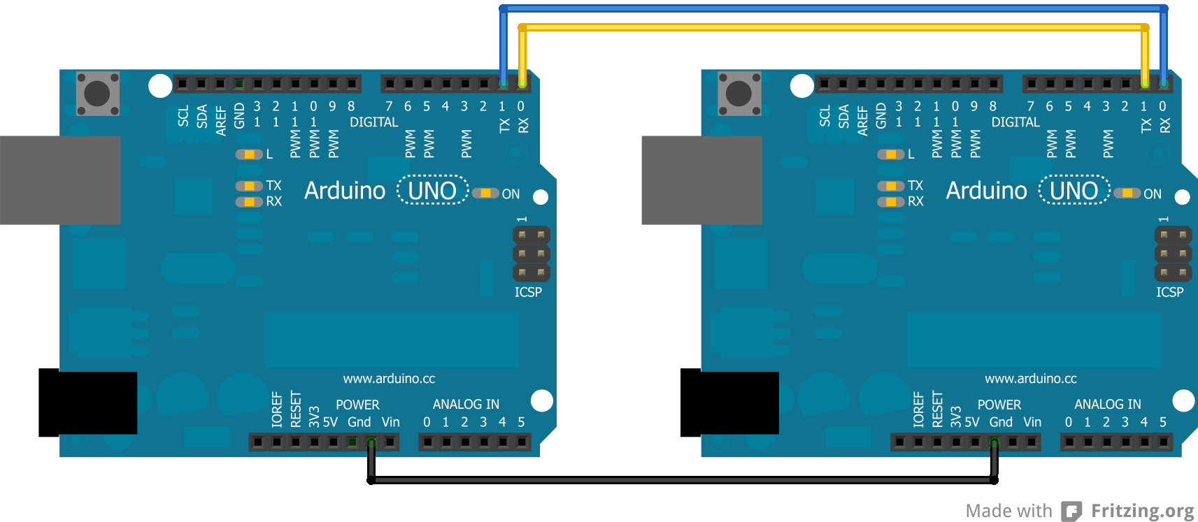
There has to be a common ground between the two or else it will not function properly. Also, note that TX goes to RX and RX goes to TX.
Coding
When sending things through serial, everything is sent in bytes. These bytes are then read one byte at a time by the other Arduino. When it is just characters being sent through the serial, it is relatively easy to convert from characters to bytes. However, if there are both characters and numbers are going through, this can lead to messing up the data because a number and a character can have the same byte value, but that does not make them the same. Numbers are also tricky because they may not actually fit in the byte.
Simple Code
The easiest way to get around this is to try to avoid using characters and numbers at the same time. This can be done by sending one character across, each with a different meaning. A good example of this comes from the Arduino Physical Pixel tutorial.
Upload the Physical Pixel code, which can be found in the Arduino IDE under: File >> Examples >> Communication, onto one Arduino.
On the other Arduino, upload:
void setup() {
  Serial.begin(9600);
}

void loop() {
  Serial.print('H');
  delay(1000);
  Serial.print('L');
  delay(1000);
}
When this is run, the LED attached to Pin 13 on the Arduino with the Physical Pixel code should flash on and off at a frequency of 0.5 Hz. To make sure this is actually the code doing that, the delays can always be changed in the above code.
In this code the job of 'H' was to turn an LED on and the job of 'L' was to turn the LED off. This can easily be applicable to getting various characters triggering more reactions.
However, depending on the application, this may not be enough and more drastic code may be required.
Complex Code
For sending data from one Arduino to another in a form that cannot be simplified, there are other options. One option is to turn everything sent from the Sender Arduino into characters and then have the Receiver Arduino read in the characters. The data is actually sent as bytes, but the Arduino can convert from characters to bytes and vice versa.
Sender Code
The sender code changes characters into bytes and, if necessary, it changes number values into characters before turning it into bytes. Below is a sample of the Sender code:
//Sender Code

char str[4];

void setup() {
  Serial.begin(9600);
}

void loop() {
  int value=1234; //this would be much more exciting if it was a sensor value

  itoa(value, str, 10); //Turn value into a character array
  Serial.write(str, 4);
}
Receiver Code
The receiver will then receive the byte array from the other Arduino and interpret it there. Below is the code for the receiver. Note that this code is intended for a Mega since it will interpret the data received from the other Arduino and then print to the Serial Monitor what it received so that the user can check it. This debugging can be avoided by using an Uno and then printing what was found onto an LCD screen that uses I2C communication.
//Receiver Code

char str[4];

void setup() {
  Serial.begin(9600);
  Serial1.begin(9600);
}

void loop() {
  int i=0;

  if (Serial1.available()) {
    delay(100); //allows all serial sent to be received together
    while(Serial1.available() && i<4) {
      str[i++] = Serial1.read();
    }
    str[i++]='\0';
  }

  if(i>0) {
    Serial.println(str,4);
  }
}
There is one flaw with this program as it is now. It results in only a character array, so if the integers were desired, they are lost without further work on the data.
Further tutorials have been made to show how this data may be manipulated by splitting strings or getting floats from the character arrays.
Optimized Multiple Pin Reads
Optimized Multiple Pin ReadsMemory Addressing
First, to understand why things are done this way, it should be known that a bool (boolean true/false) is only 1 bit. 1 for true, 0 for false. However, computers have an addressing system for memory, which cannot go directly to a single bit. An address usually goes to a 8 bit chunk of memory (a byte), which is also usually the same size as an int data type.
Think of it like trying to write a postal address to a room in a house. The address will take you to the house, but not inside. So, we can't just keep it in its own variable.
Furthermore, it would be wasteful to waste 7 bits for every bool declared. 8 bools can be put all into one integer - all next to each other in memory - to save space. How do you seperate them? How do you get just one bit out of a chunk of bits? With boolean logic!
Port Manipulation
To be as efficient, Arduino groups pins together into 8 bit "int" variables. Using boolean logic, you can perform operations on pins yourself, instead of using the built-in functions. This is called Port Manipulation. There are 3 groups of 3 variables. First, the pins are broken up into groups of 8 based on number.
- D: Arduino digital pins 0 to 7
- B: Arduino digital pins 8 to 13
- C: Arduino analog pins 0 to 5
Then, there are 3 types of registers which can perform different actions, each with a the corresponding letter replacing the '#':
- DDR#: Data Direction Register.
- Sets whether the each pin is read from or written to.
- PORT#: Port I/O
- Can write to each pin a high or low state, but can also be read
- PIN#: Pin Input
- Can read the current pin states of the pins in input mode.
Reading the pins
Pins are oranized in the register from lowest number at the right, to highest number at the left In this example, pins 11 through 13 are set as INPUT. Pins 11 and 13 are currently high at the moment, but pin 12 is low.
| Pin: | NA | NA | Pin 13 | Pin 12 | Pin 11 | Pin 10 | Pin 9 | Pin 8 |
|---|---|---|---|---|---|---|---|---|
| Decimal Value | 128 | 64 | 32 | 16 | 8 | 4 | 2 | 1 |
| PINB | 0 | 0 | 1 | 0 | 1 | 0 | 0 | 0 |
| SelectP13 | 0 | 0 | 1 | 0 | 0 | 0 | 0 | 0 |
| SelectP11 | 0 | 0 | 0 | 0 | 1 | 0 | 0 | 0 |
As you can see, if you were to print the value of PINC with pins 13 and 11 high but 12 low, the value with 32 + 8 = 40.
To select a single pin out of the PINC register, bitwise AND it with an int in the same place as the pin. So, PINB & SelectP13 = 13, or 0B00100000. Conditions in C++ will be true for any nonzero value. If Pin 13 were low, then the result would have been 0, or 0B00000000.
Programming Example
First, you have to set whether the pins are in read or write mode. Since this is often done exclusively in setup and only once per program, it is not as important to optimize this. It may be easiest to just use pinMode() to set the states instead of the more advanced ways described below with the DDR# register.
void setup() {
    pinMode(11, INPUT);
    pinMode(12, INPUT);
    pinMode(13, INPUT);
}
void loop() {
    //This condition is a single CPU operation
    //pins 11,12, and 13 are all in the PINB group at the left
    if ( PINB & 0B11100000 ) {
        Serial.println("Pin 11, 12, or 13 were high");
    }

    //this condition requires dozens of operations
    if ( digitalRead(11) || digitalRead(12) || digitalRead(13) ) {
        Serial.println("Pin 11, 12, or 13 were high");
    }

}
In the above example, the slower second method each digitalRead must first figure out which register the pin is in, select it with a bitwise and, and return it to the condition. Then, each pin state must be ORd together.
Obviously, this case is not a typical one, but there are other uses. For example, one could write to several pins at once. This optimal method becomes extremely important when speed is an issue. When reading pins every few microseconds on interrupts, it can be beneficial to first store the whole register into a buffer, then do the required comparisons later in order to insure that all changes are being captured. Otherwise, data could be lost if the interrupt function is interrupted before it can complete.
Build Arduino Sketches from CLI with Make
Build Arduino Sketches from CLI with MakeReasons
The Arduino IDE has a lot of nice features. It's so easy, it's really one of the main reasons why you would choose to buy an Arduino over other options. It can be annoying sometimes though. If you want to distance yourself from the IDE, but still like the Arduino plaform, it's really as easy as just making a really simple text file and running "make".
By getting a command line interface, you can also automate the build and upload process. You can detect ports, or upload to multiple Arduinos at once.
Installation
Ubuntu command:
sudo apt-get install avrdude make gcc-avr arduino-mk
Usage
Create a text file called "Makefile" in the same folder as your project
ARDUINO_DIR  = /usr/share/arduino

TARGET = projectName         # The same as your ino file name

BOARD_TAG    = uno           # can also be mega2560
ARDUINO_PORT = /dev/ttyACM0  # be sure to change this to the port used by your board

#Can add Arduino libraries. Example:
#ARDUINO_LIBS = EEPROM

ARDUINO_DIR  = /usr/share/arduino
AVR_TOOLS_PATH = /usr/bin

include /usr/share/arduino/Arduino.mk
Once you have that file, all you need to do is just say:
make upload
If you aren't using an Arduino Uno, you can check which boards are available with:
make show_boards
Advanced Usage
It might be helpful to just autodetect all of the Arduinos connected and upload the same image to all of them. Here is a nice simple way to do that with bash:
Makefile:
ARDUINO_DIR  = /usr/share/arduino

TARGET = tempTargetName
BOARD_TAG    = uno
ARDUINO_PORT = ${arduino}

ARDUINO_DIR  = /usr/share/arduino
AVR_TOOLS_PATH = /usr/bin

include /usr/share/arduino/Arduino.mk
Then make a bash file. This will be executed instead of the make command.
make.sh:
#!/bin/bash

#look for any Arduinos.
#The current ones were connected recently and within the same minute

for a in `ls -lt /dev/ttyACM* | awk 'BEGIN{first = 1} {if (first) {current = $9; first = 0} if ( $9 == current ) { print $10} else{exit} }' `
do
    echo "uploading to $a"
    make arduino=$a upload
    if [ $? -ne 0 ]; then
        echo "nonzero return status"
        exit
    fi
done
Now, all you need to do to compile and upload to all recently connected arduinos is run:
bash make.sh
Kernel - Event driven Delays and Intervals
Kernel - Event driven Delays and IntervalsReasons to use Kernel
delay() is Bad
When you use delay or delayMicroseconds in Arduino, nothing else can happen until the delay is finished, which can be a huge problem if you have more than one thing going on simulteneously, as will always be the case when building a more advanced robot.
Imagine that you want to check a sensor once a second. Easy enough. Just delay then check the sensor. What if you want to blink an LED on and off every 40ms, but still checking that sensor. Any delays used by one will mess up the timing on the other. If you delay one second after checking the sensor, the light will not blink during that time. You could make a fixed number of blinks between sensor checks, but that is inflexible and accumulates error.
Problems with Alternatives
Two alternatives already exist. Both are based on the idea of constantly asking "can I go yet?" in an if statement.
- You can check the times yourself, but that requires a lot of work and can make the code hard to read.
- You can also use Metro , which wraps the check up into a nice class where you just set an interval and run a .check() method.
I really like Metro, but it still requires the program to be written somewhat linearly instead of in seperate functions, and it is not really meant to be used for one-time delays.
If you are using an Arduino Due, there the Scheduler library that provides an easier interface, but is exclusive to the Due's ARM CPU.
Events are Easy and Powerful
If you've ever dealt with GUIs or Javascript, you're probably comfortable with events. They're a nice way to make the most use out of a single threaded application (like a browser window, or an Arduino) because, as long as you avoid any blocking, things happen when they're supposed to.
Essentially, each "task" is a function which gets called only when the "event" happens. The event, for example, can be a timing trigger or a user interaction.
Kernel takes care of timing the event calls. It can automatically maintain both run-once and run-repeatedly events simulteneously.
Since Kernel is keeps track of which event needs to happen next, but still using delayMicroseconds, better timing precision and consistency is achived.
Other Potential Benefits
Since a Kernel is such a advanced framework, with a little additional programming, some really useful features can be added:
It could keep track of how long a task takes to complete, or give more important tasks priorities, and factor that into decisions of which task can go when, like a true kernel would for process management.
A single "background" process could be run, without interfering too much with the time-sensitive tasks. Which could be accomplished with the runNow method.
How it Works
There is a queue of functions. They are in the ordered chronologically. Since it is a linked list, the functions can be inserted in before other functions, but after others.
Now all that Kernel does is look at the next task coming up to see if it is the right time. If it is not time yet, it will use delayMicroseconds to give it a precise start time.
Repeating events (called intervals) will then be re-added to the queue in the correct chronological order.
Since the soonest event is always in the front of the queue, no events will be passed over while using delay.
Basic Usage
First, download the kit - ![]() kernelTest.zip. It includes Kernel (GPL by me), fastDelegate (Public Domain from Code Project), a modified version of the QueueList library (from the Arduino Playground), and a simple Arduino .ino file to show some basic usage.
kernelTest.zip. It includes Kernel (GPL by me), fastDelegate (Public Domain from Code Project), a modified version of the QueueList library (from the Arduino Playground), and a simple Arduino .ino file to show some basic usage.
The usage is intentionally very similar javascript, which uses setInterval and setTimeout for repeating and one-time tasks respectively.
//may need to use <> instead of ""
// depending on if you installed Kernel as a library.
#include "kernel.h"

Kernel kernel; //this should be a global, so other files can use it too.

void test() {
    Serial.println(  micros()  );
}

void setup() {
    Serial.begin(19200);

    //add a function to interval. It will run every 10,000 microseconds.
    kernel.setInterval(10000UL, test); // UL means the unsigned long
}

void loop(){
    //should avoid any code that could cause much delay here

    // runNext decides whether to delay or run the next function
    kernel.runNext();
}
That's it! In a lot of ways, it's even cleaner than a Metro. Of course, there is a lot more going on under the hood.
This above example shows how to add an interval. It is also possible to add a timeout by using setTimeout instead, which will only happen once.
Sidenote about Unsigned Longs (UL)
Intervals and timeouts are set in microseconds. Since microseconds add up so quickly, Arduino deals with them as unsigned longs, but they still overflow (go back to zero) after about 70 minutes. The setInterval and setTimeout functions take durations in microseconds stored in unsigned longs too. Sometimes, it might be necessary to say that the what the type of the constant you have in your code is. For example, if you are dividing numbers, you might prefer to use a 2.0 instead of a 2, since a 2 is an integer and might typecast the other number into an integer also - removing the decimal precision. Similarly, problems might or might not happen with very long numbers represented by long and unsigned long. Arguments will by typecast into an unsigned long, so it will probably not be necessary to specify "UL" at the end of your numbers.
Advanced Usage
Remove a task
Both setInterval and setTimeout return a unique integer PID. It can be used to later remove a task from the queue.
int newPID = kernel.setInterval( 100000UL, test);
kernel.clearInterval( newPID );
Remove all tasks
Perhaps all current tasks need to stop happening. Maybe you've come accross an error and want to stop everything.
kernel.stopALL();
Break Up a Long Task
Sure, you could create a seperate task for a background task, but if your loop runs quickly enough, you can essentially run kernel like you might a Metro, except it is only checking the next pending task.
void loop() {
    for( int index = 0; i < hugeArray; i++ ) {
        //do some operations

        // will not delay until next task, tasks may be overdue
        kernel.runNow();
    }
}
You need to do either runNow() frequently, or do runNext() at the end. Otherwise, no events will be called.
Clock Display Without Serial
Clock Display Without SerialIntroduction
This is a tutorial on how to build a clock display using only an Arduino, a Shift Register, and 4 digit seven segment display.
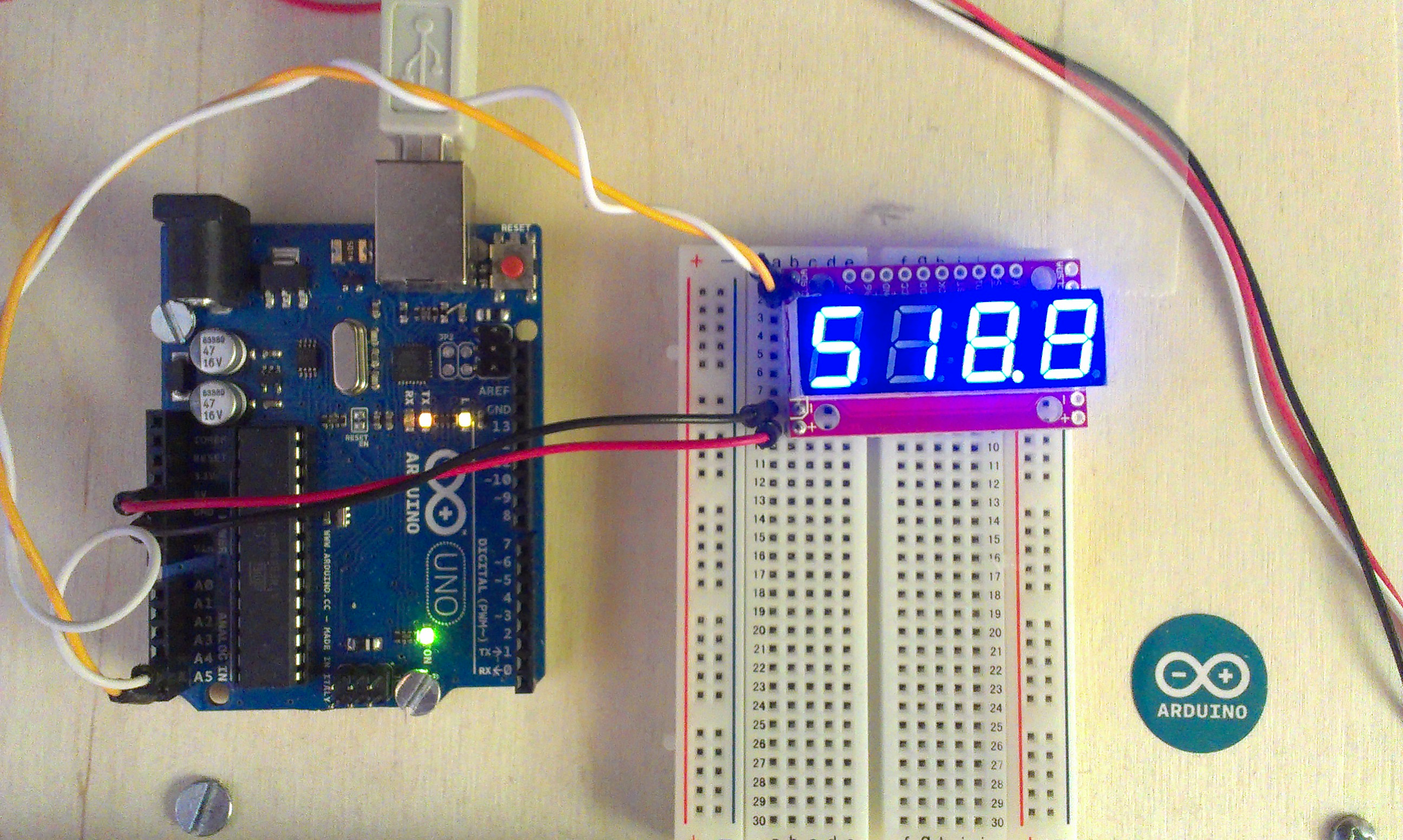
The end result should look something like this mess:
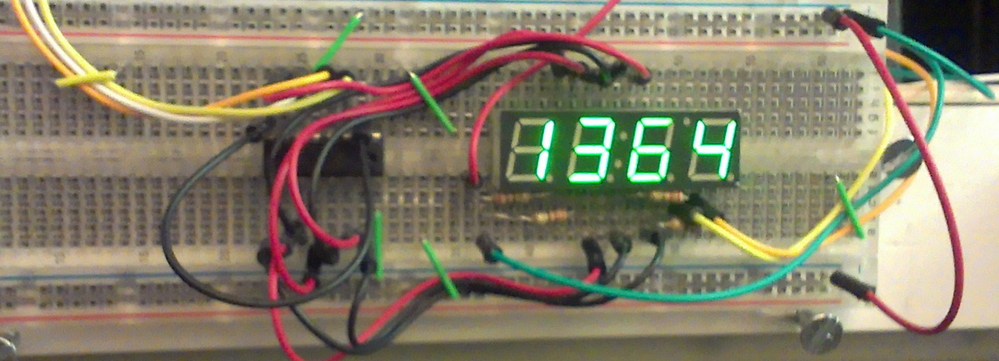
In this image, you can see an accelerometer to the left, which is not a part of this tutorial.
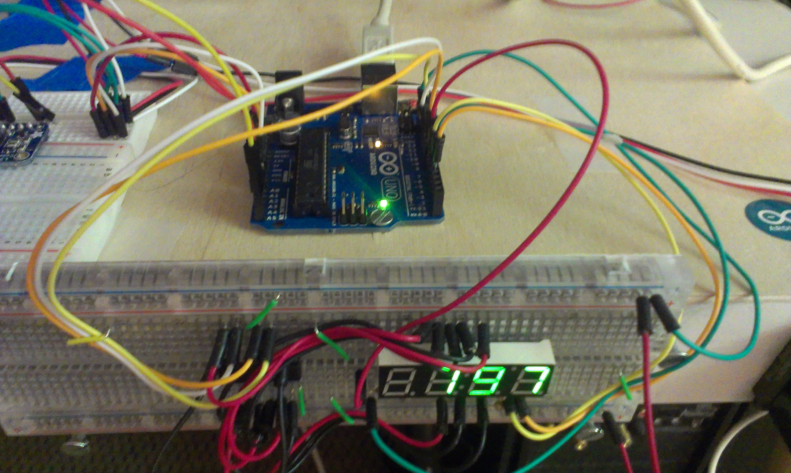
Clearly, the whole thing gets very messy. As a result, I would recommend one that works by serial, offloading this wiring and refreshing. There is a great Arduino-based one by Sparkfun , and a cheaper one available at Adafruit . It's $10-$13 for the serial ones, but these bare displays are 2$, the shift register is 3$ for a pack of three, uses at about 20 breadboard wires, 8 pins on your Arduino, and requires that the Arduino be able to cycle through the digits of the display frequently. The extra cost is minimal and saves a lot of effort.
Parts List
- .39 inch 4 digit 7 segment display (BL-Q39A-42UG-21 from Adafruit )
- 74HC595 Shift Register (bought from Adafruit )
- Arduino Uno
- 4x 220Ω resistors
- Lots of breadoard wire
Pinout of Display
I had some trouble getting the display to work according to the spec sheet, so I just reverse engineered it.
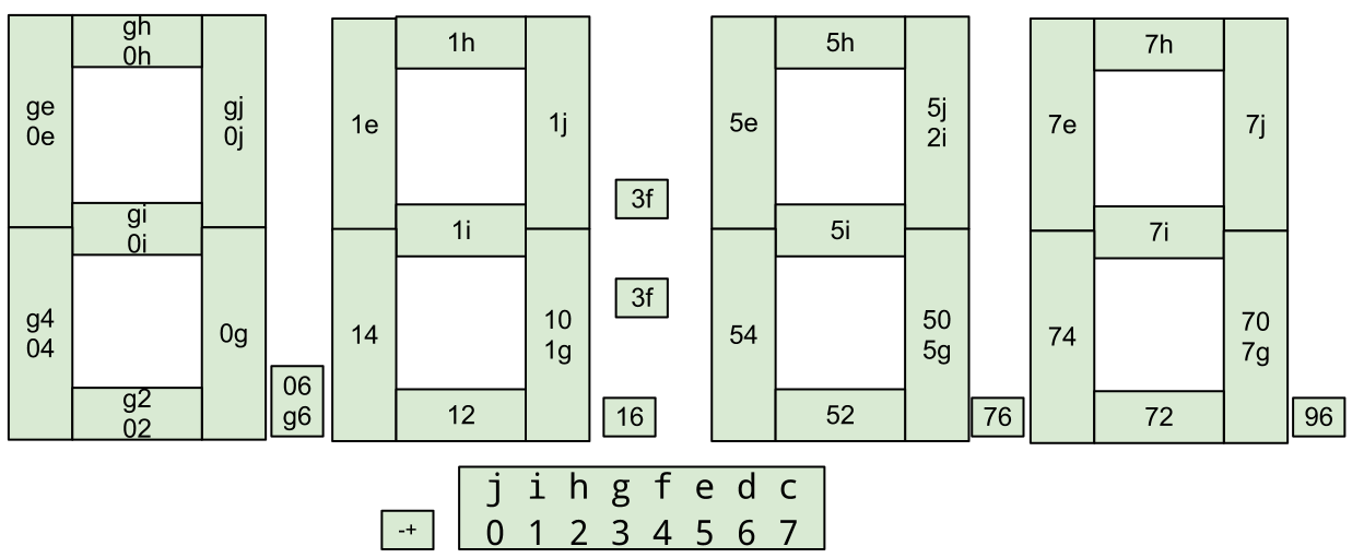
The numbers on the digit segments are in the order of negative and positive. So, to light up the left most digit, 0 must be negative (grounded), and each of the segments can be lit with by giving each of the right most lettered pins a positive. As a result, the grounding pin must be cycled, and the other digits must be positive. Also, apparently the 0 and g pins are interchangable.
Wiring Diagram
I made a wiring diagram in Fritzing. Even like this, it still looks daunting, but at least you can tell what goes where.
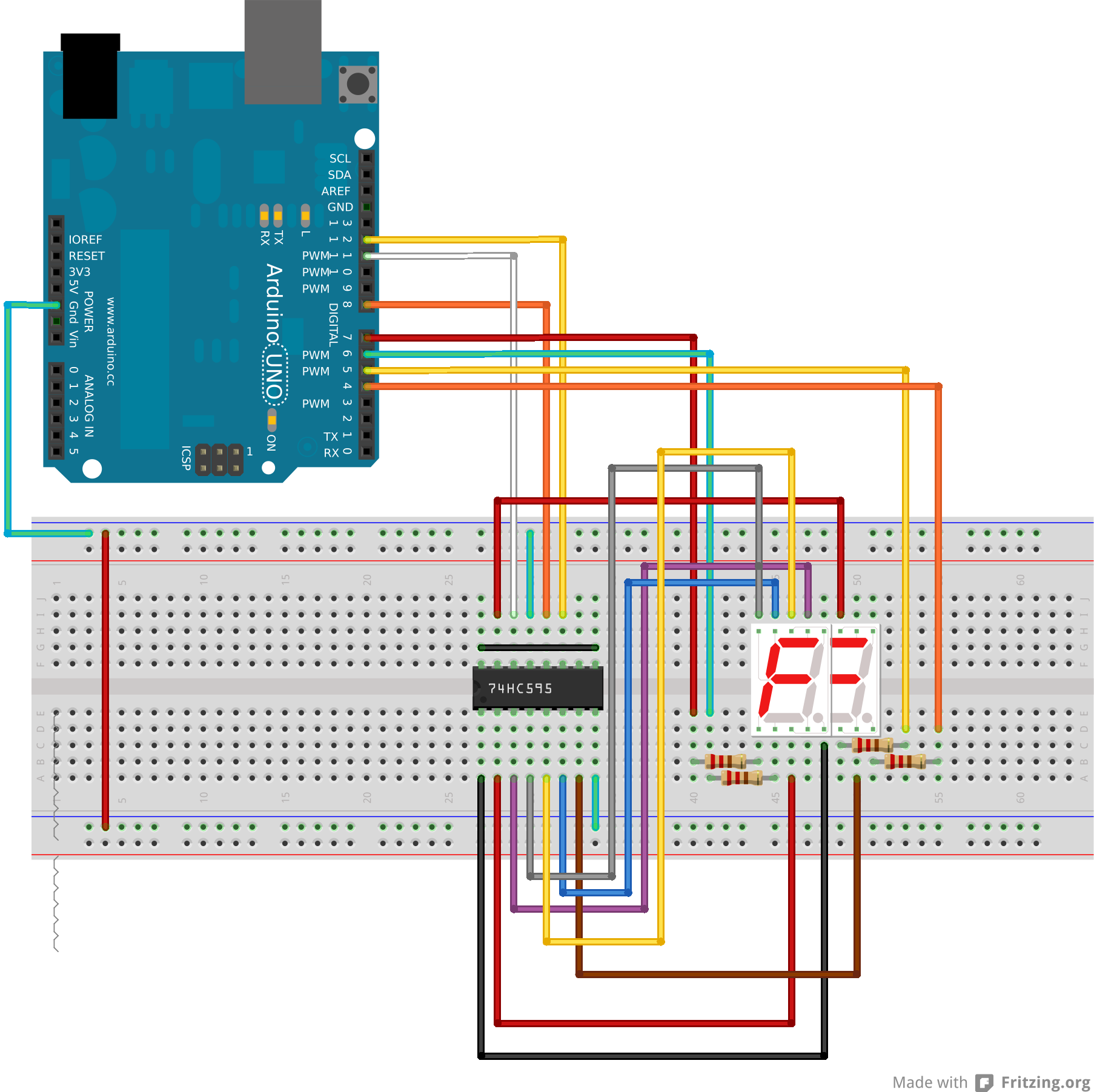
I couldn't find something for a 4 digit seven segment display that has 8 pins on each side. So, I just used two 7 segment displays overlayed so they had the right number of pins. It looks ugly, but pretend it's ok. The wires should still be the same.
The svg and Fritzing files are attached at the bottom as well for your convenience.
Code
The code is also somewhat complicated. There are two main problems: converting a character to a a map of on or off values for each pin, and the fact that the display has to be refreshed ever few milliseconds. I took care of both problems by writting my own class. It should actually be universal for all 7 segment displays with minimal adjustment. I wrote it to utilize the Kernel library I made so that the timing is non-blocking.
The .ino file:
#include "kernel.h"    //handles timing in non-blocking way
#include "SevenSeg.h"  //maps characters to pin outs on shift register

// declare some global instances of the classes
Kernel kernel;
SevenSeg sev;


int count = 0;
void increment() {
    sev.display( count );
    count++;
    if ( count > 9999 ) {
        count = 0;
    }
}


void setup() {
    //set up the seven segment display class
    sev.setup();
    sev.setShift( 8, 12, 11);  //which pins the
    sev.setDigits( 7,6,5,4 );
    sev.setSegmap( 0, 1, 2, 3, 4, 5, 6, 7);

    //takes an Unsigned Long (UL) for the microseconds between intervals
    kernel.setInterval(100000UL, increment);
}

void loop() {
    kernel.runNext();
}
The SevenSeg.h class:
The SevenSeg class should be universal, but you have to do a few things to set it up first.
First, you need to tell it which pins the shift register is on. This is fairly straightforward with:
setShift(latch, clock, data)
The arguments should correspond to the spec sheet for your shift register
- latch: may be denoted as ST_CP, or RCLK
- clock: may be denoted as SH_CP, or SRCLK
- data: may be denoted as DS, or SER
Next, you need to tell SevenSeg which pins are used to toggle which digit is being lit in the cycle. These should be real pins on the Arduino addressable by digitalWrite. The digits are in order from left to right.
setDigits( 7,6,5,4 );
Then, you need to map the digits of the display to the pins on the shift register
setSegmap( ... )
The value of the argument is the pin on the shift register. The order of the arguments says which segment it belongs to according to this:
/*
  0 5555555555555 4
  00 55555555555 44
  00             44
  00             44
  00             44
  00             44
  0 6666666666666 4
  1 6666666666666 3
  11             33
  11             33
  11             33
  11             33
  11 22222222222 33   777
  1 2222222222222 3   777
*/
Conclusion
Download the Arduino code: ![]() sevSegTest.zip
sevSegTest.zip
Again. It's a really really good idea to just get one that works over serial.
Clock Display With Serial - Sparkfun
Clock Display With Serial - SparkfunIntroduction
These seven segment displays are managed by an extra Arduino embedded in them. As a result, far less wiring and code is required for your project, since it is all encapsulated in this nice package. Here is the finished project:
Basic Wiring (I2C)
| Arduino | Serial7Segment |
|---|---|
| A5 | SCL |
| A4 | SDA |
| 5V | + |
| GND | - |
The wiring is really straightforward. On the top sides there is an SDA and SCL, which go to A4 and A5 respectively on your Arduino Uno. If you are using a different Arduino, check the documentation on the Wire library to see which pin you should use.
On the bottom sides, there is a plus and minus, which should be hooked up to the 5V and GND pins respectively on your Arduino.
Basic Code
I based my code on the public domain code posted by sparkfun. I added:
- Number formatting (space padded to the right)
- Use snprintf to handle overflows
- Funciton for decimal printing using floats
- Beware! Floats on Arduino are really innacurate. I get 0.01 error on just a 3 digit number!
/* Serial7Segment is an open source seven segment display.
 To get this code to work, attach a Serial7Segment to an Arduino Uno using:
 A5 to SCL
 A4 to SDA
 VIN to PWR
 GND to GND
*/

#include <Wire.h>

#define APOSTROPHE  5
#define COLON       4
#define DECIMAL4    3
#define DECIMAL3    2
#define DECIMAL2    1
#define DECIMAL1    0

//This is the default address of the OpenSegment with both solder jumpers open
#define DISPLAY_ADDRESS1 0x71

void setup()  {
  Wire.begin();       //Join the bus as master

  Serial.begin(9600); //Start USB serial communication at 9600 for debug prints

  //Send the reset command to the display
  //this forces the cursor to return to the beginning of the display
  Wire.beginTransmission(DISPLAY_ADDRESS1);
  Wire.write('v');
  Wire.endTransmission();

  //High Brightness
  Wire.beginTransmission(DISPLAY_ADDRESS1);
  Wire.write(0x7A);         // Brightness control command
  Wire.write(100);          // Set brightness level: 0% to 100%
  Wire.endTransmission();
}


float cycles = 0.0;         // TEST DECIMAL SENDING
void loop() {
  cycles+= 0.1;             // increment decimal
  Serial.print("Cycle: ");
  Serial.println(cycles);

  i2cSend(cycles);          //Send the decimal to the display

  delay(1);                 //a very small delay to prevent flickering
}

void i2cSend(float numberToPrint) {
    int decimalPlace = -1;

    //find decimal place, fix the position of leftmost digit to the left
    if ( numberToPrint < 0 ) {
        i2cSend( int( numberToPrint * 100 ) );
        decimalPlace = DECIMAL1;
    }
    else if ( numberToPrint < 10 ) {
        i2cSend( int( numberToPrint * 1000 ) );
        decimalPlace = DECIMAL1;
    }
    else if ( numberToPrint < 100 ) {
        i2cSend( int( numberToPrint * 100) );
        decimalPlace = DECIMAL2;
    }
    else if ( numberToPrint < 1000 ) {
        i2cSend( int( numberToPrint * 10) );
        decimalPlace = DECIMAL3;
    }
    else {
        i2cSend( numberToPrint );
    }

    if ( decimalPlace != -1 ) {
        Wire.beginTransmission(DISPLAY_ADDRESS1); // transmit to device #1
        Wire.write( 0x77 );                       // send decimal command
        Wire.write( 1 << decimalPlace );          // send the place using bitshift
        Wire.endTransmission();                   // Stop I2C transmission
    }
}

//Given a number, chop up an integer into four values and sends them over I2C
void i2cSend(int numberToPrint ) {

  // use snprintf. It will align the number to the right of the string
  // snprintf truncates the number after the first few digits
  char str[5];
  snprintf(str, 5, "%4d", numberToPrint);

  i2cSendString( str );

  // the number is too big - mark that it was cut off.
  if ( numberToPrint > 9999 ) {
      Wire.beginTransmission(DISPLAY_ADDRESS1);   // transmit to device #1
      Wire.write( 0x77 );                         // send decimal command
      Wire.write( 1 << APOSTROPHE );              // indicate an "overflow"
      Wire.endTransmission();                     // Stop I2C transmission
  }
}

//Given a string, i2cSendString sends the first four characters over i2c
void i2cSendString(char *toSend) {
  Wire.beginTransmission(DISPLAY_ADDRESS1); // transmit to device #1
  for(byte x = 0 ; x < 4 ; x++)             // for each of the 4 characters
    Wire.write(toSend[x]);                  // Send the character from the array
  Wire.endTransmission();                   // Stop I2C transmission
}
Documentation
Here are some other links to SparkFun's documentation:
- Product Page: https://www.sparkfun.com/products/11442
- Tutorial: http://www.sparkfun.com/tutorials/407
- Code: https://github.com/sparkfun/Serial7SegmentDisplay
Long based Decimals
Long based DecimalsIntroduction
Arduino has floats that are only accurate to about 6-7 digits. When combined with the fact that floats cannot represent certain decimal values well ( like .1 or .3 ) because they are expressed as negative powers of base 2, you may often see error - especially when full value is printed, or the output is truncated instead of rounded.
I have written a class here that basically stores a whole number into a long. Similar to a float, there is even an "exponent" field that says where the decimal point is in the whole number. Unlike a float, operations are done in base 10 (onto a base 2 number). In exchange for the flexibility of true floating point number in the range of possible values, we gain greater precision in the nearer to zero area - the area firmly within the range of the long (-2,147,483,648 to 2,147,483,647). The smaller the left hand side (LHS) of the decimal place is, the more precision is available for the right hand side (RHS) of the decimal.
Usage
So far, all I have is a really basic class that only handles the construcor and the bare minimum needed for printing.
#include "longDecimal.h"

void setup() {
    Serial.begin(9600);
    Serial.println( "BEGIN TEST:");

    LongDecimal dec(131,158272);

    Serial.print( dec.getLHS() );
    Serial.print( '.' );
    Serial.println( dec.getRHS() );

    LongDecimal dec1(-131,158272);

    Serial.print( dec1.getLHS() );
    Serial.print( '.' );
    Serial.println( dec1.getRHS() );


    LongDecimal dec2(12345678,158272);

    Serial.print( dec2.getLHS() );
    Serial.print( '.' );
    Serial.println( dec2.getRHS() );
}

void loop() {}
Output
BEGIN TEST:
131.1582720
-131.1582720
12345678.15
Class
You might be able to figure out what is going on just based on the documentation on the code for the class as it is:
#include <Arduino.h>

class LongDecimal {
    private:
        long decimal;              //the left and right side of decimal
        unsigned int decimalPlace; //where the decimal is in the above variable

    public:
        //constructors
        LongDecimal( long lhs, long rhs );
        LongDecimal( float f );

        //type conversions
        long getLHS();
        long getRHS();
};

LongDecimal::LongDecimal( long lhs, long rhs ) {
    decimalPlace = 0;

    //shift lhs to the left in the long
    long lhsSpace = abs(lhs);
    long rhsSpace = 1;

    // float the LHS all the way to the left of the long - may not be desirable
    while ( 214748364L > lhsSpace ) { // maximum long divided by ten
        lhsSpace *= 10L;

        decimalPlace++;
        rhsSpace *= 10L;
    }

    // put the LHS into the main decimal variable
    decimal = lhs * rhsSpace;


    // float the right hand side to align with LHS
    //moves right if necessary - losing precision
    while ( rhs > rhsSpace ) {

        rhs /= 10;
    }
    //moves left if necessary
    while ( rhs * 10L < rhsSpace ) {
        rhs *= 10L;
    }

    // put the RHS into the main decimal variable
    // add to the decimal if positive subtract if negative
    if ( lhs < 0 ) {
        decimal -= rhs;
    }
    else {
        decimal += rhs;
    }

}


//shifts decimal to the right until it is just the left hand side of the decimal
long LongDecimal::getLHS() {
    long LHS = decimal;
    for( int i = 0; i < decimalPlace; i++ ) {
        LHS /= 10;
    }
    return LHS;
}
//removes the left hand side of the decimal by subtraction
long LongDecimal::getRHS() {

    long LHS = getLHS(); //removes RHS, but is shifted right

    //shift back to the left
    for( int i = 0; i < decimalPlace; i++ ) {
        LHS *= 10;
    }

    return abs(decimal) - abs(LHS);
}
Organized EEPROM storage
Organized EEPROM storageIntroduction
EEPROM is a permanent memory. It will remain even after the Arduino is restarted. It can be reprogrammed around 100,000 times, so it is substantially less resilient than the flash storage or a hard drive. It is also kind of slow (3ms per byte). The Ardiono Uno has 1KB of EEPROM.
The compiled program is uploaded to flash storage (not EEPROM), which is faster and larger. So, if you can, it is better to write keep as much as possible in the C++ file.
Sometimes it can be convenient or more reliable to use the EEPROM. You could log sensor readings to EEPROM so that the data will still be there even if it loses power. Alternatively, you could use an SD shield and get more, more reliable, and more portable storage.
If you have multiple Arduinos for a project that do the same tasks, but want a way to differentiate them despite having identical programming, you could flash an ID number to the EEPROM.
Simple Usage
Reader
This reader is used after the writer to get the value from the EEPROM:
#include <EEPROM.h>

int address = 0;

void setup() {
  Serial.begin(9600);

  int value = EEPROM.read(address);
  Serial.print("Read: ");
  Serial.println( value );
}

void loop() {
}
Writer
Here is a simple writer that just writes an int of 123 to the first byte in the EEPROM:
#include <EEPROM.h>

int address = 0;

void setup() {
  Serial.begin(9600);

  int value = 123;
  EEPROM.write(address, value);

  Serial.println("Done writing");
}

void loop() {
}
Structured and Organized Storage
A cool trick in C++ is to sort of overlay a structure onto an area of memory - taking advantage of data structure alignment. This organization method is used heavily in file manipulation, for example: reading a bitmap.
The cool thing about this is that you can mix datatypes and not have to worry about reading things in the right order. As long as the struct remains the same when you read it after you write it.
You might see this struct example and want to use it as a seperate class in a seperate header, but I didn't do that primarily because it depends so heavily on the struct you make. It is actually possible to make an encapsulated version of this by using templates. A template is a way to pick a data type for some elements in a class. Some good examples of ways they are useful are vectors and linked lists.
This class should only be used once in a project without any modification. By simply adding a fixed offset to the EEPROM.read and EEPROM.write methods, multiples could be used.
#include <EEPROM.h>

typedef struct                    /**** EEPROM STORAGE STRUCTURE ****/
{
    //stuff in here gets stored to the EEPROM
    unsigned short count;         /* A count of values stored */
    long           sum;           /* A running total of values */
    char           str[10];       /* A string label */
    int            values[100];   /* Array of values collected */
    boolean        complete;      /* a flag for whether gathering is finished */
} EEPROMSTORAGE;

// a class to manage the struct
class Permanent {
    private:
        // the actual eeprom gets stored here
        // the struct is overlayed onto this storage
        byte buffer[ sizeof(EEPROMSTORAGE) ];

    public:
        Permanent();   //constructor - reads the eeprom
        void write();  //a function to write to the eeprom

        //this pointer makes the buffer's contents easily accessed
        EEPROMSTORAGE * store;
};

//read the eeprom into the buffer
Permanent::Permanent() {
    for( int i = 0; i < sizeof(EEPROMSTORAGE); ++i ) {
        buffer[i] = EEPROM.read(i);
    }
    //overlay the pointer to the storage onto the buffer
    store = (EEPROMSTORAGE *) buffer;
}

//write the buffer into the eeprom
//be careful writting too often to the eeprom. It only has 100,000 writes
void Permanent::write() {
    for( int i = 0; i < sizeof(EEPROMSTORAGE); ++i ) {
        EEPROM.write(i, buffer[i]);
    }
}

//make an instance of the managing class called eeprom (in lower case!)
Permanent eeprom;

//this is just a demo of how you would access and write the data
void setup() {
     Serial.begin(9600);

     //check to see what was already in the eeprom. serial print it.
     Serial.println( eeprom.store->str );

     //fill the buffer's store with some data
     eeprom.store->count = 0;
     strcpy( eeprom.store->str, "Hello!");

     for(int i = 0; i < 50; ++i ) {
         int sensorVal = i*3+2;
         eeprom.store->values[i] = sensorVal;
         eeprom.store->sum += sensorVal;
         eeprom.store->count++;
     }
     eeprom.store->complete = true;

     //write the buffered data to the eeprom
     eeprom.write();
}

void loop() {}Blender Arduino Model
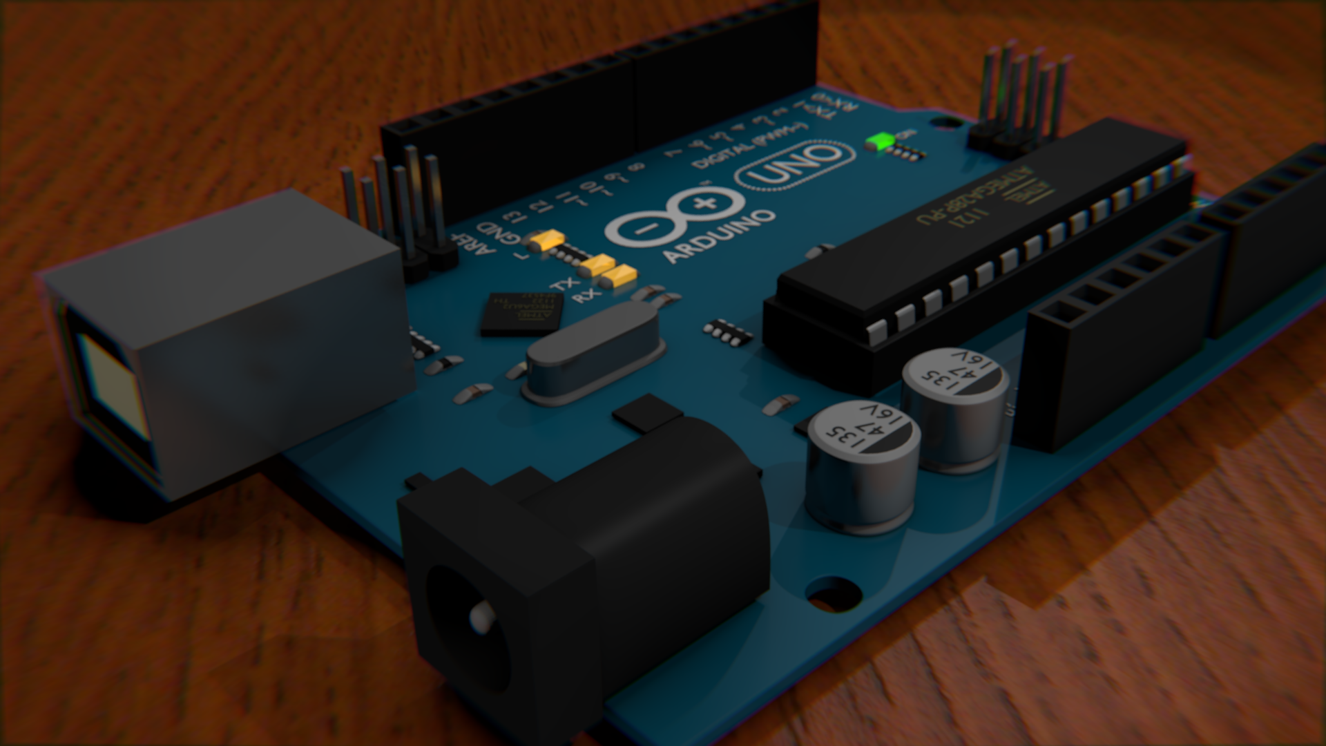
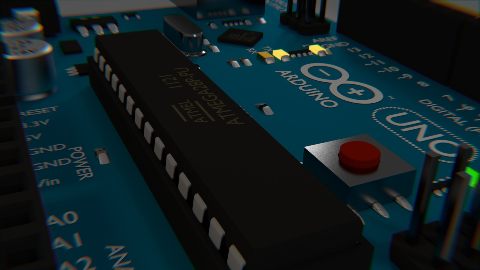
Blender Arduino Model
Results
I could not really find any great Blender models of the Arduino Uno on the internet, so I decided to make my own. Mine was made entirely from scratch and does not use any image textures (except the wood in this demo). It features most of the details of the Uno, but does not have the printed circuitry. It was modelled off an image and some eyeballing for sizes, so it may not necessarily be to scale, but it looks close enough for Blender work. Even the text is there, using the default Blender font. The Arduino logo is actually a mesh of a circle. The most notable chips have the proper text on them, and the plugs even are shaped like sockets.

See the bottom of this post for the .blend files, or read more to see how it was done.
Progress
I kept renders from each of the steps along the way. I will describe each set of renders with a paragraph for each render in line from left to right.
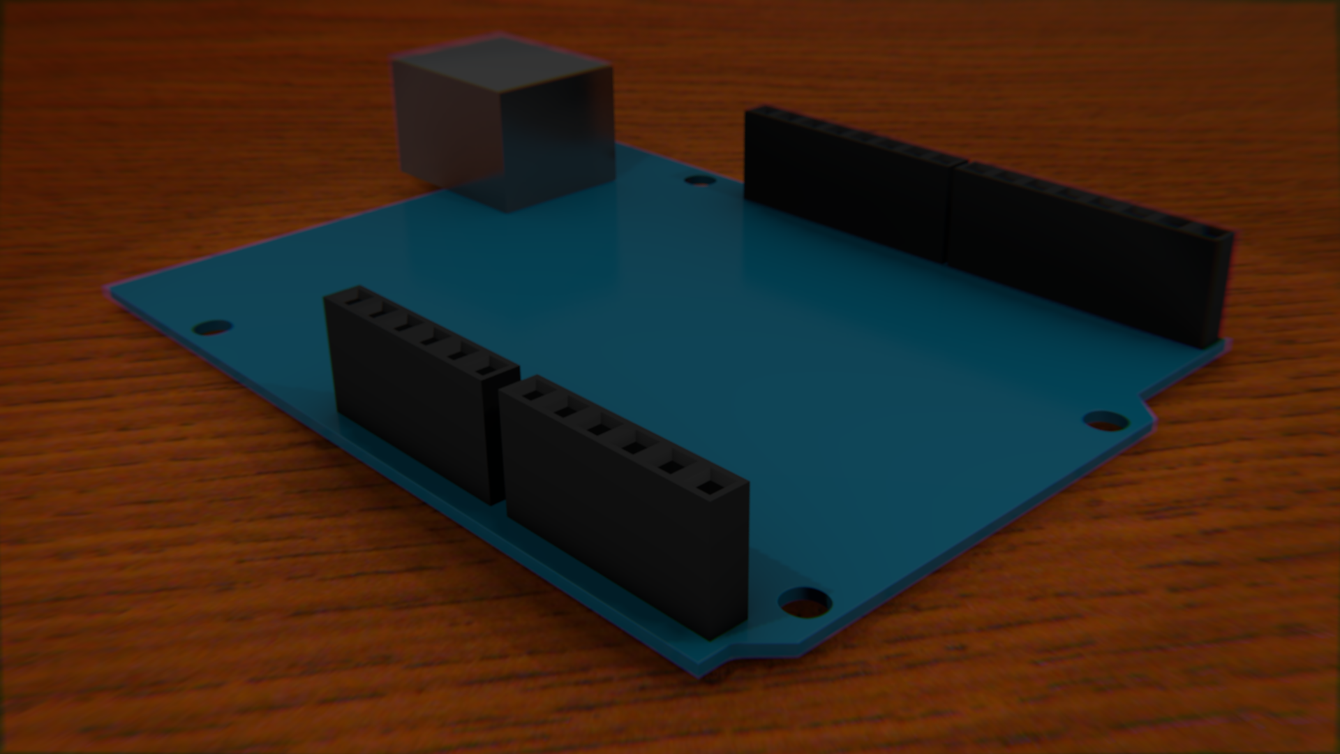
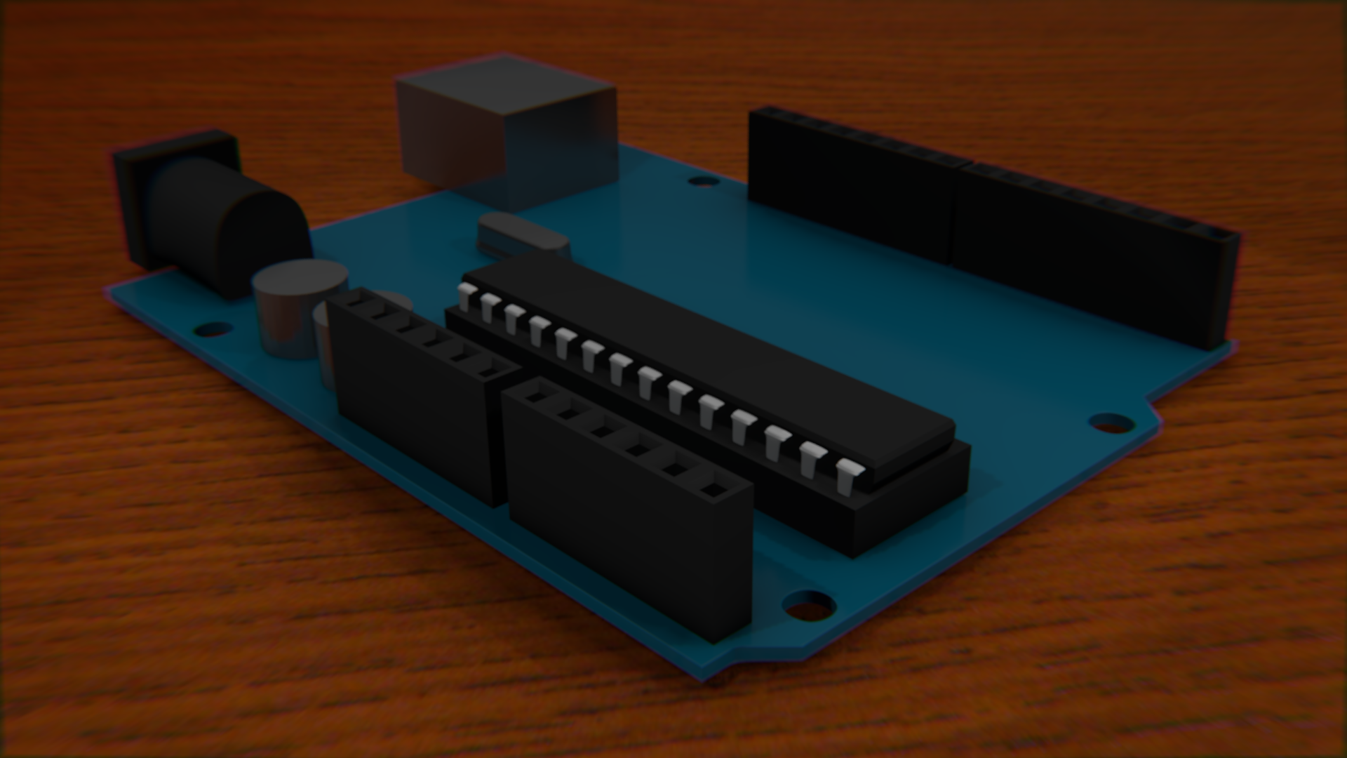
So, I start by tracing the board from an image, which was actually easy. Then "loop cut and slide" was done several times to square off the holes. Once the square holes are made, the subdivision modifier is applied. The edges on the top and bottom of the squares must be hardent with shift+e, otherwise it will look more like a worn down area than a drilled hole. The USB connection was easy. Picking the right material for it was the important part. It should be reflective and still have some roughness to it. Just one pin was made, then an array was used to duplicate the pin in a row. Then different sets were made by Shift+D for duplicate.
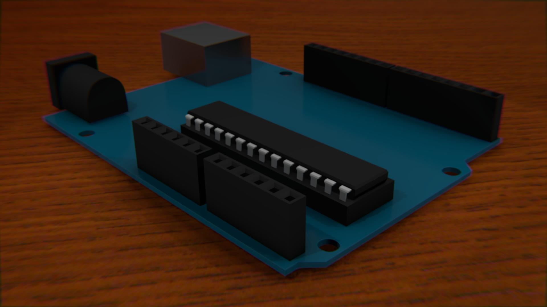
The power socket was easy, with just a cube. Extrude one face twice - once bigger then another the same size. Then subdivisions are applied to give the back end the rounded look. All edges but the top back two should be at their hardest with shift + e. The ATMEGA is actually really easy to do except for the pins, which never quite seem to look right.
I started trying to add the capacitors and the piezo by using cylenders, but that was the wrong way to go about it. Subdivisions are a lot easier.
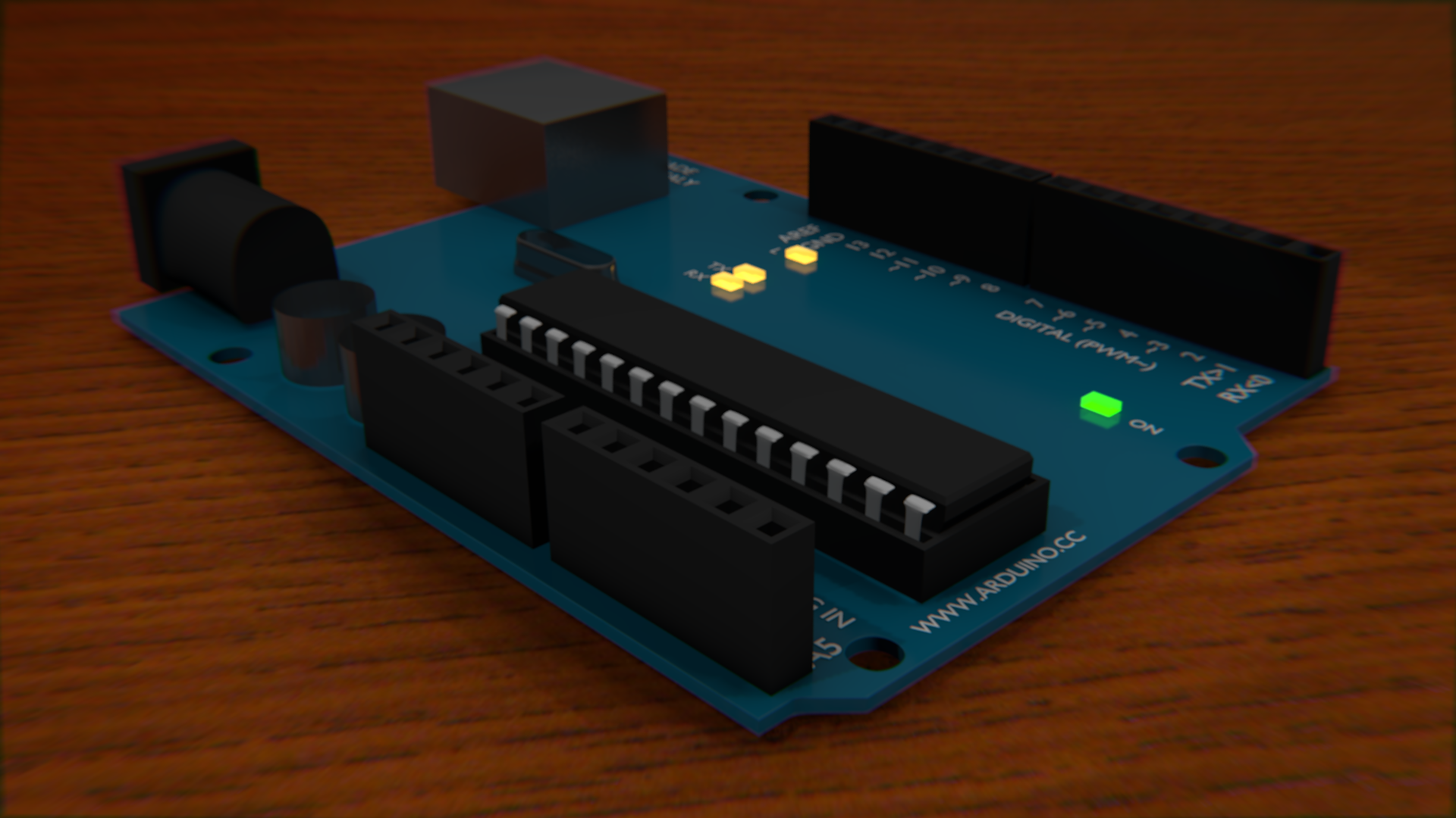
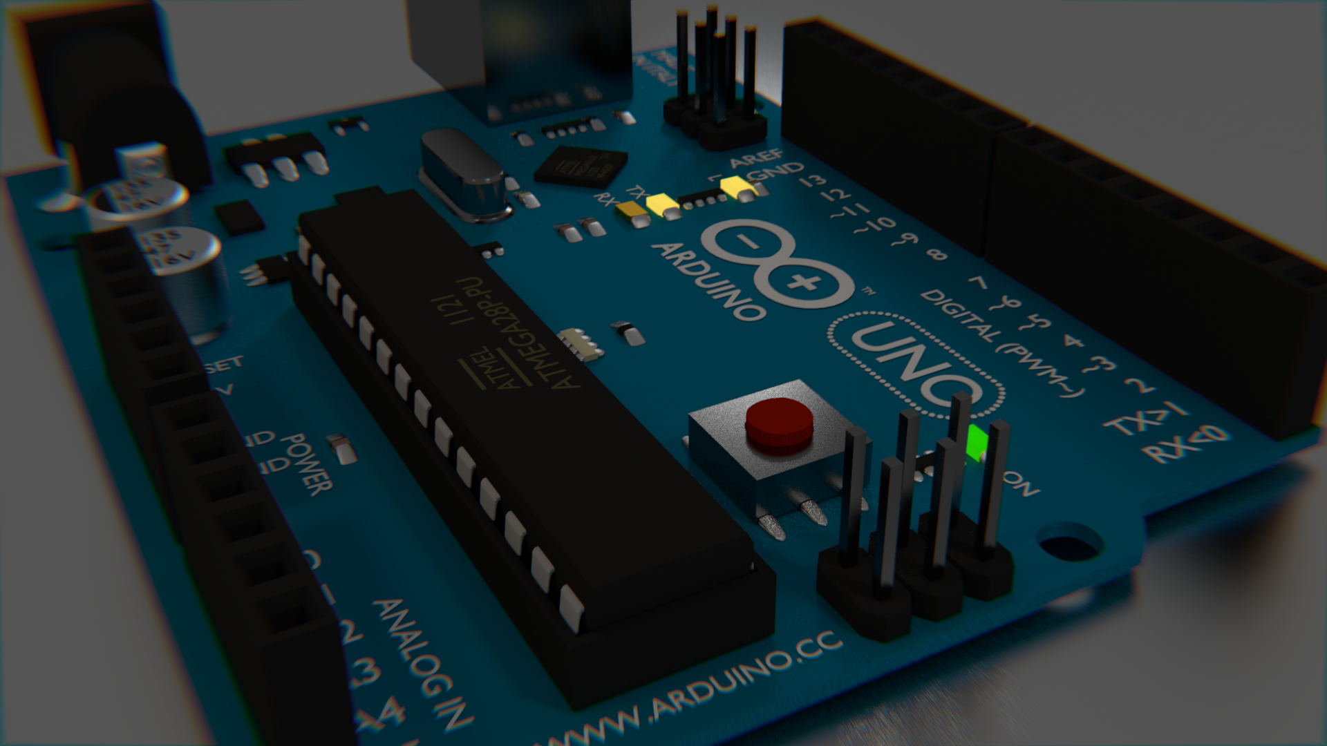
I realized that adding the text was going to be really important to making it look right. It was actually easy enough to add it in exactly the right places due to the use of a "background image" on the camera. When in wireframe mode, you can see both the text and the image you are tracing. The font is clearly wrong when looking at the comparison image, but it is not so obviously wrong when just looking at these images. The biggest difference is that the I is supposed to have the caps on it. The LEDs were added and turned on, just because they could be. It was later pointed out that it would be impossible for an arduino to have both on at the same time.
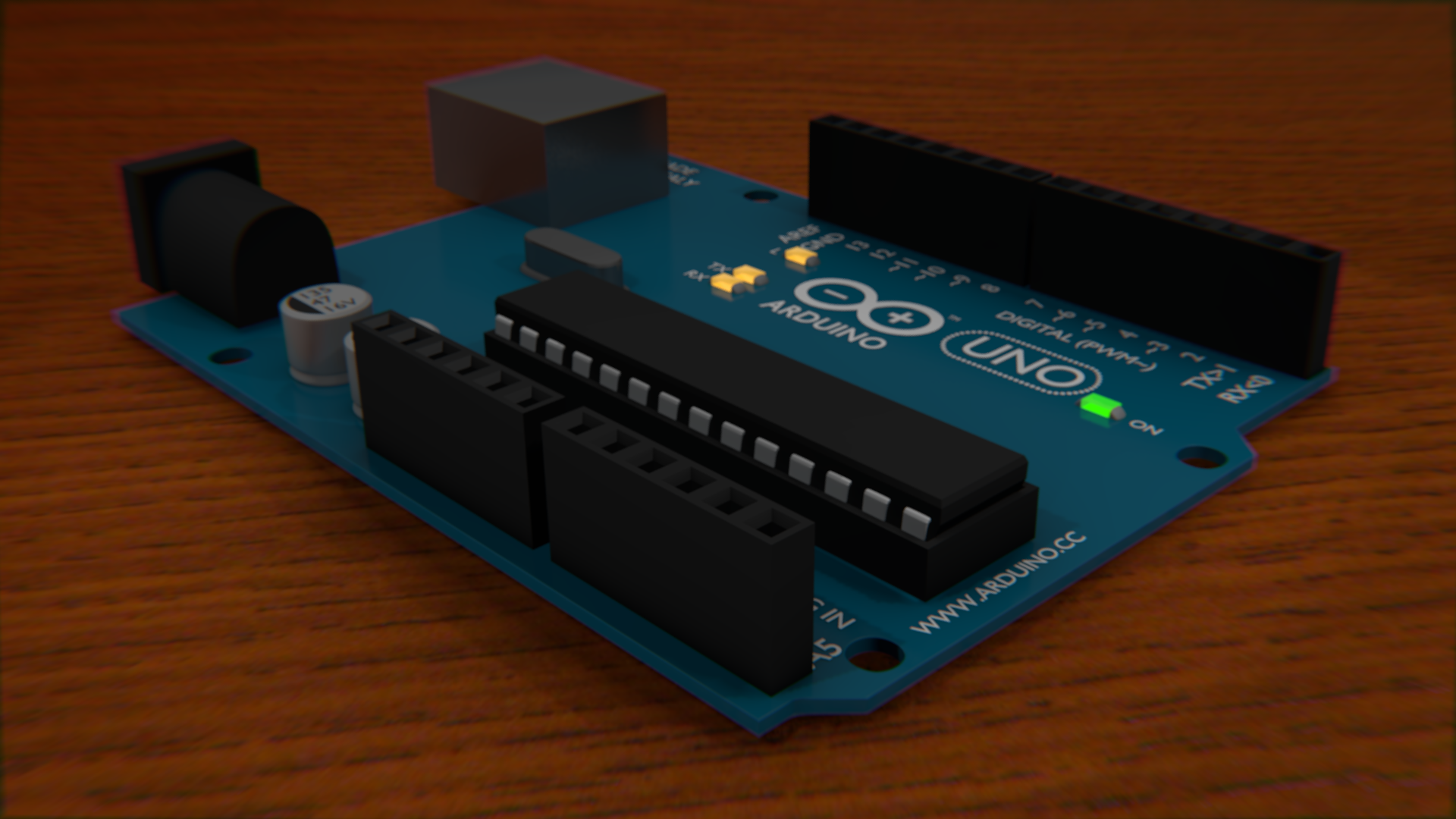
The arduino logo is simply a circle mesh extruded inward, then deformed a little bit. Here, I also fixed the capacitor and piezo to use subdivisions, and added the accurate notches and protrusions to each. I really like the way the black text on the capacitors looks. Again, the black side is just a circle.
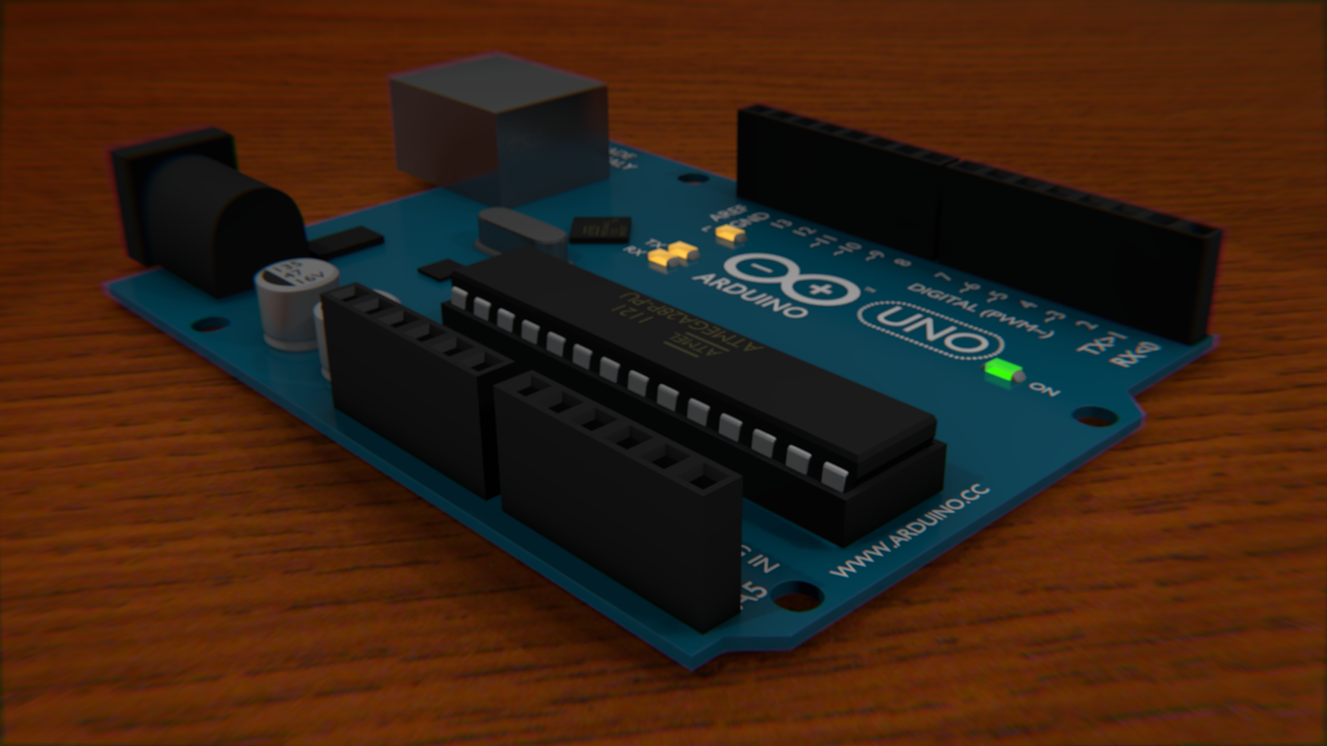


Of course the Arduino needs the text on the ATMEGA chip!. I also added some black boxes for the smaller chips that are scattered on the board. Here, a couple more black chips are being added to the board.
Here, I added the sockets to the USB and Power blocks. They did not have the interior parts before, but you couldn't see that. I still don't really like the way the interior of the USB socket looks, but I didn't really care as much about that feature.
I also wanted to add all of the little resistors and tiny components that litter the board, but decided to test how just this one works before duplicating it. I also tweaked the matte plastic texture a bit by making its specular less intense.
I then duplicated the resistors all over the place wherever they were needed. The pins that... well, actually I don't know what those ones that protrude do - I have never used them. Anyway, they were easy enough to make I didn't even use an array. I just duplicated them.
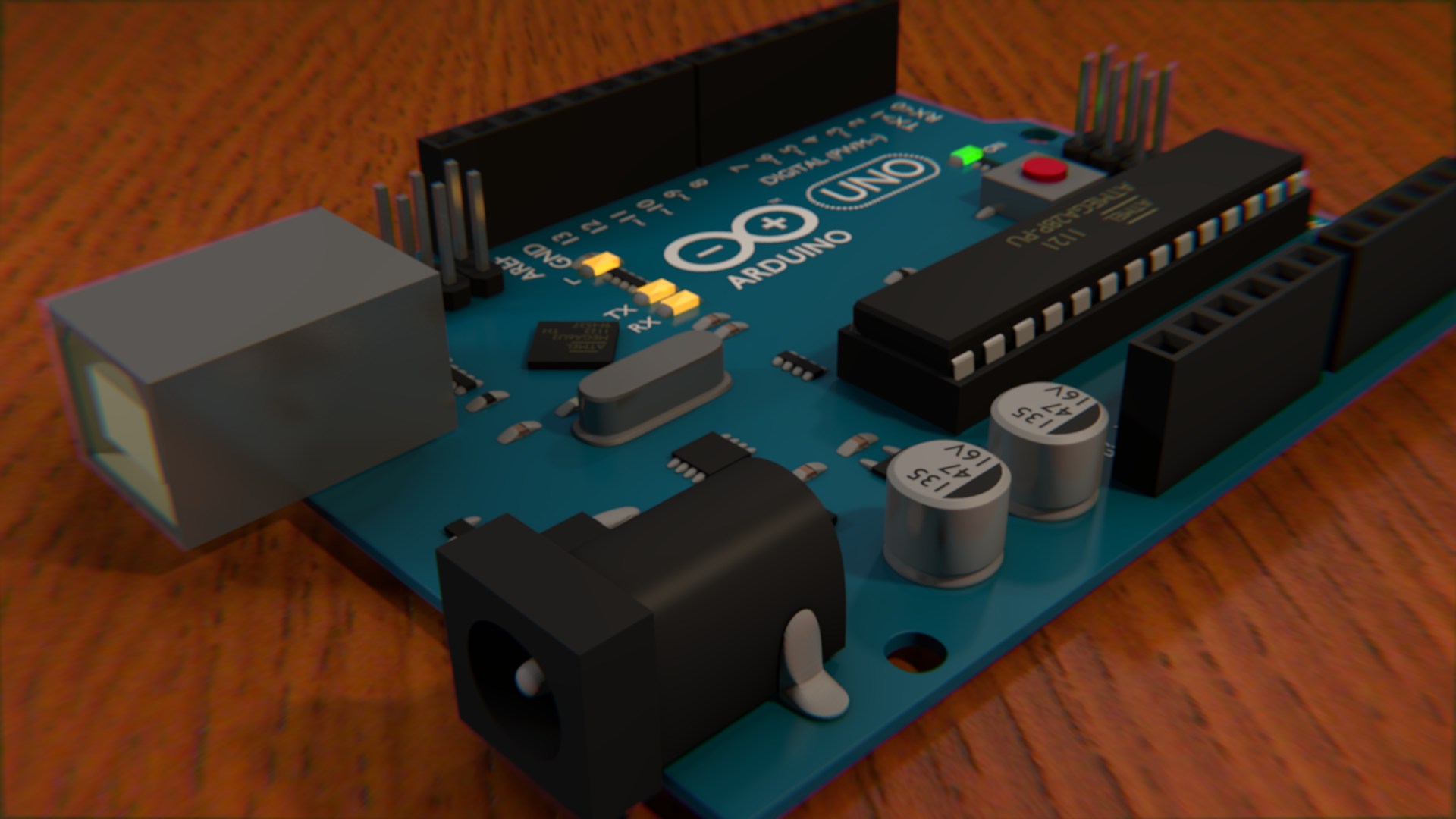
And of course, the reset button had to be added. That was just a box with a subdivided box on top. I also added connecting solder to a bunch of components. It's supposed to be mildly reflective, since it uses the same material as the capacitors, but it never really shows in these demos - probably because there is no skymap.
Cycles Tests
Cycles is a next-generation rendering engine in Blender. It is completely different than the current renderer, so the materials and textures system is entirely different and doesn't transfer back and forth. In theory, it is superior due to the fact that it all light bounces off things onto others. For example, if you have a light in your home that points upward toward the ceiling - as long as the ceiling is a light color it will still light the rest of the room since the light bounces off the ceiling too. The default blender render does not do this by default - but can be made to with the indirect lighting feature.
I struggled with the environment lighting in Cycles. The world material made a huge change in the overall lighting, and no matter what I tried nothing seemed to look quite right. However, the components themselves tended to have much better looks in cycles. I also decided to switch to a glossy demo surface just because It sort of looks nice with it's reflectivity. In some ways, these renders look nicer, and in some ways they look way worse.
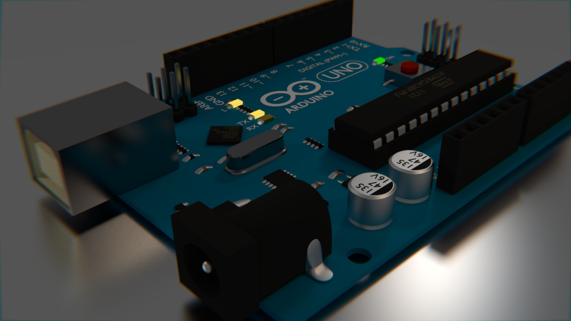


Really, converting it to cycles was as simple as just enabling "use nodes" on all the materials and then changing it to glossy in most cases. Very little tweaking was needed with the exception of the LEDs, which needed to be emission types, but they didn't look quite right when they were just emitting, so I mixed an emission type with a regular one so that it was looked a little more in place.
I sort of wish that the LED's looked better than they do. They glow, but they don't really light up their surroundings as much as I would like, which is made extremely obvious by the dim environment lighting I settled with in cycles.
LCD - Sainsmart HD44780 / LCD2004
LCD - Sainsmart HD44780 / LCD2004Introduction
This is a very simple LCD display that has a two wire serial interface. It displays characters, not pixels. It can show 20 characters in a row and 4 rows. They are fairly inexpensive at retail - only about $10. They have a toggleable backlight and a variable contrast.

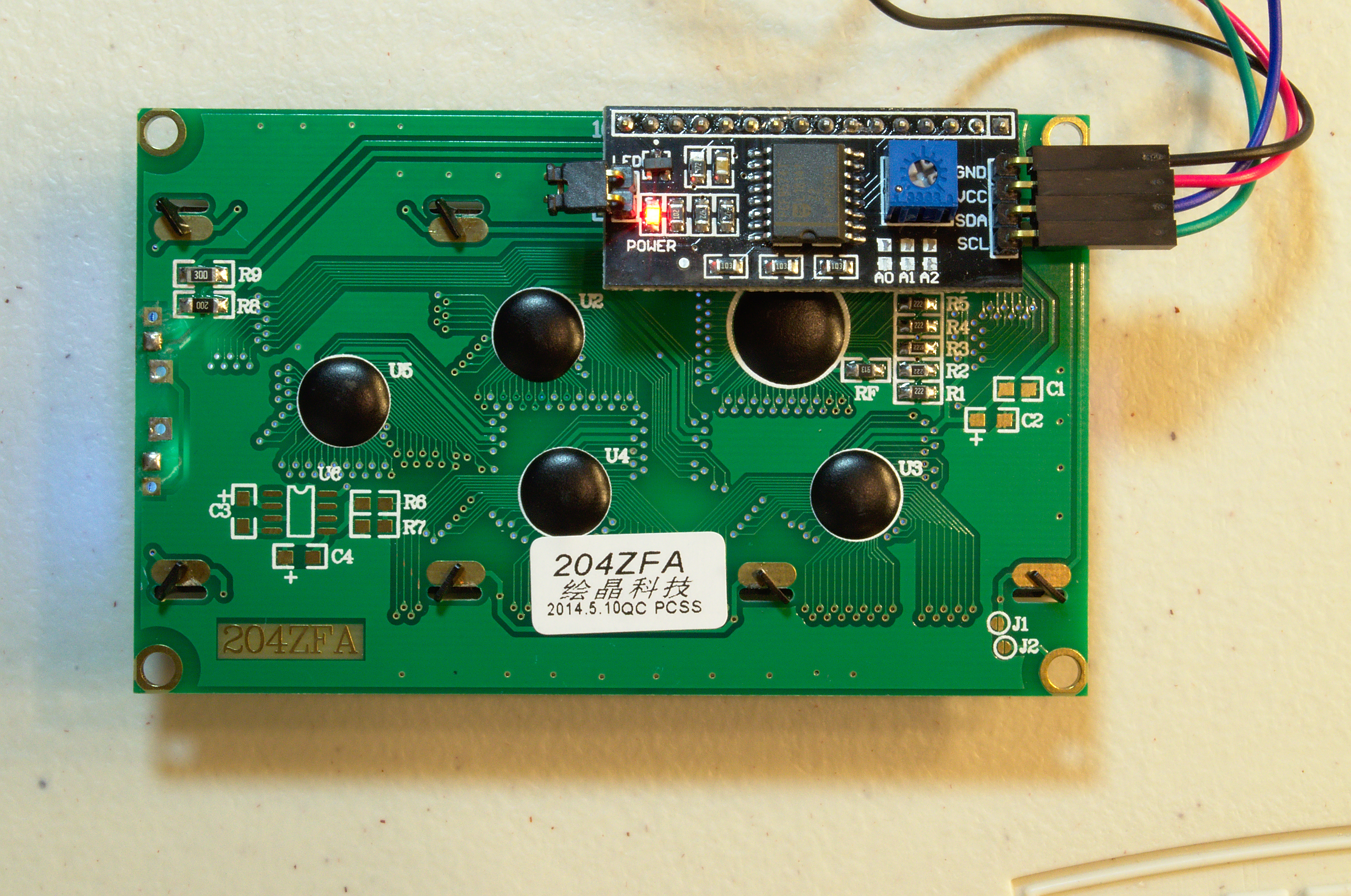
Wiring
The serial controller (or backpack) takes 5V, so connect the 5V and GND to the 5V and GND on the Arduino. The SDA and SCL pins are trickier. Depending on your Arduino, it could go any number of places, as seen in the table at the right.
| Board | SDA | SCL |
| Uno | A4 | A5 |
| Mega2560 | 20 | 21 |
| Leonardo | 2 | 3 |
| Due | 20 | 21 |
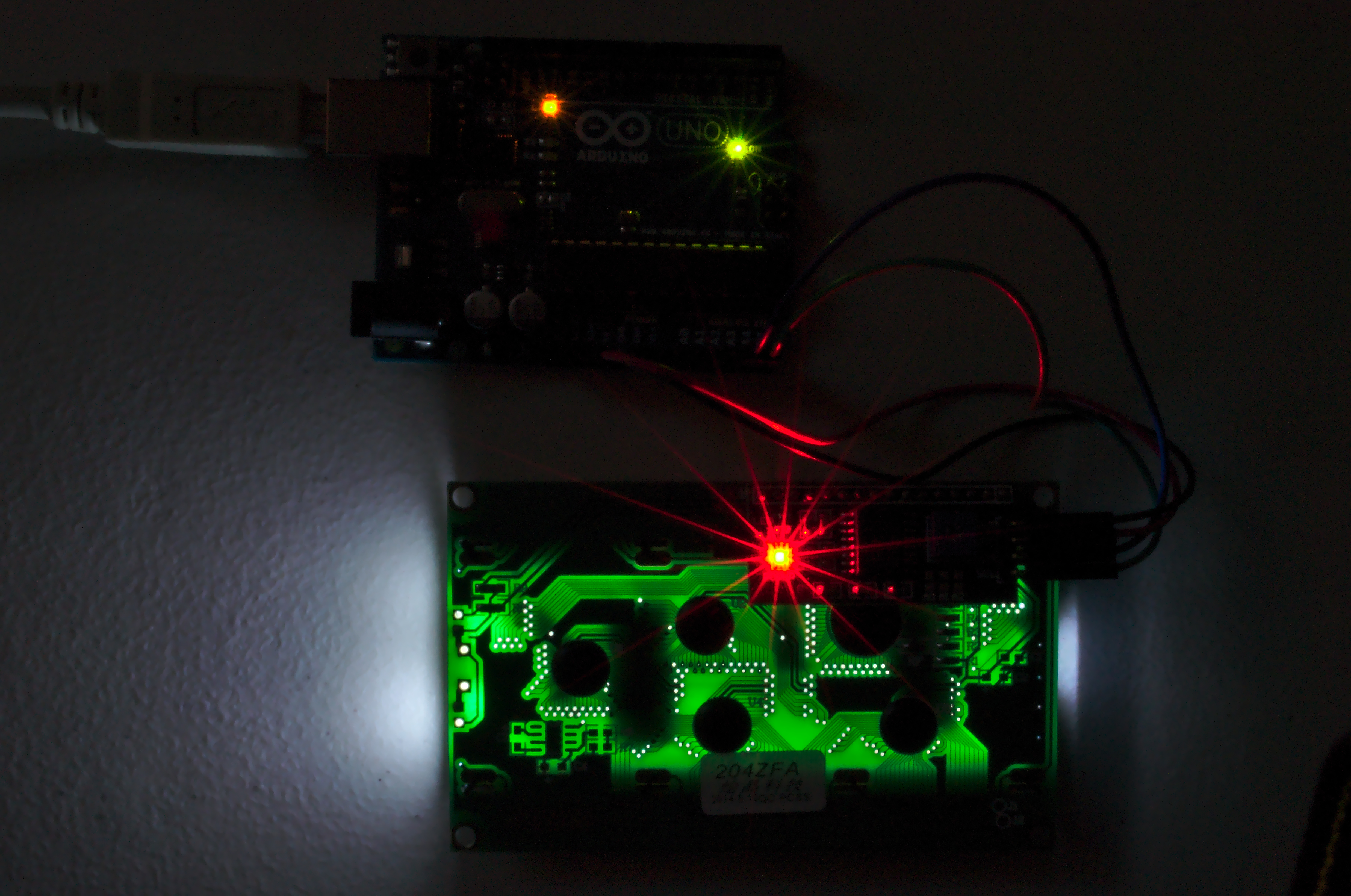
The most common board is the Uno, and the wiring of it can be seen here. Where SDA is the blue wire and SCL is the green wire - as is convention.
Coding
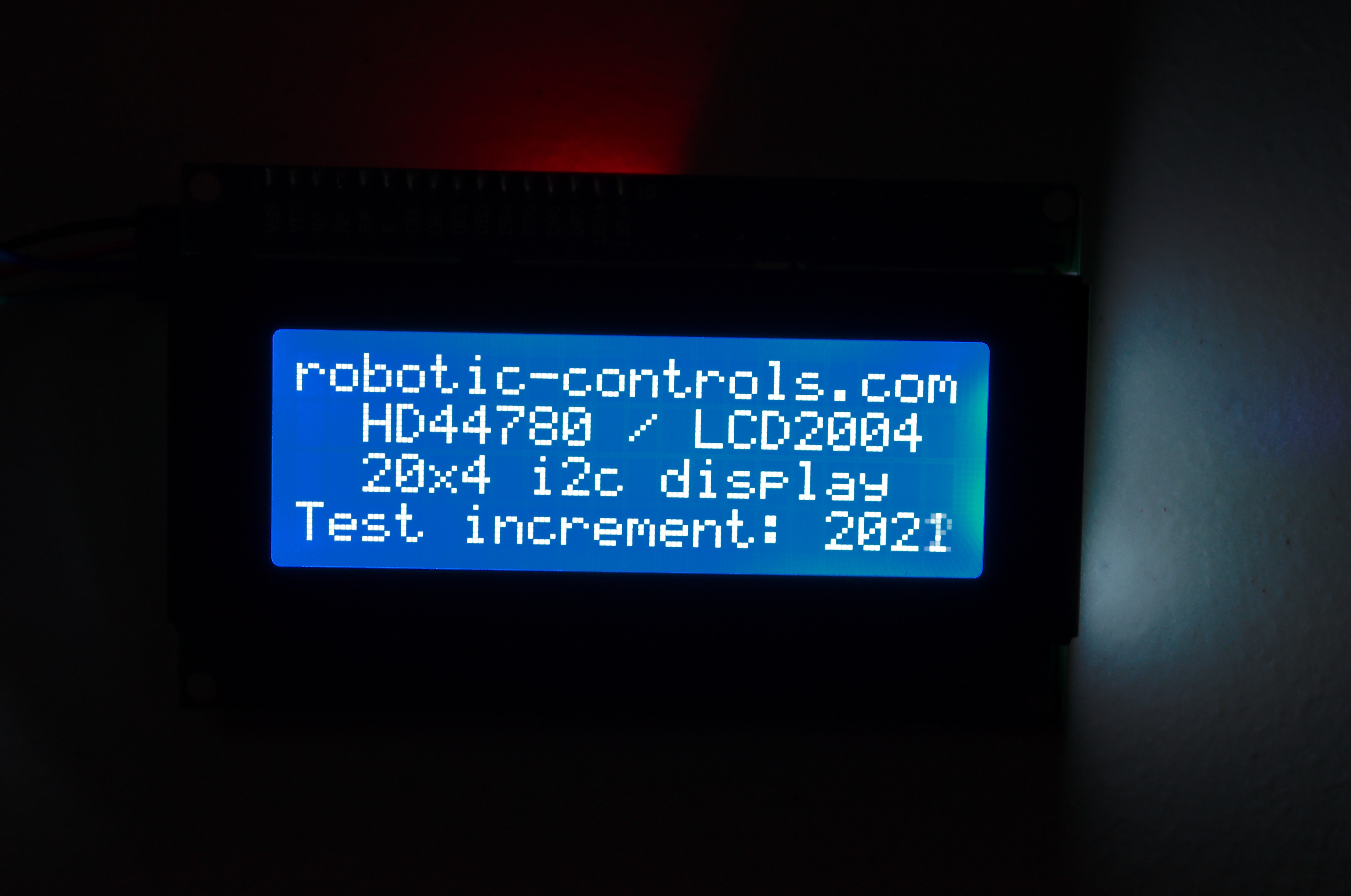
This code displays the information shown in the pictures above. It requires that you have some libraries installed. I have attached the version I used for convenience and preservation. However, the library is originally available from here, and a more up-to-date version may be available there.
The library must be installed in your Arduino folder. The folder location is:
| Windows | %HOMEPATH%/My Documents/Arduino/ibraries/ |
| OS X | ~/Documents/Arduino/libraries/ |
| Linux | ~/Documents/Arduino/libraries/ |
Download the LiquidCrystal library .zip folder and extract the whole folder into the libraries folder for your system above.
#include <Wire.h>
#include <LiquidCrystal_I2C.h>

#define I2C_ADDR    0x27  // Define I2C Address where the PCF8574A is
                          // Address can be changed by soldering A0, A1, or A2
                          // Default is 0x27

// map the pin configuration of LCD backpack for the LiquidCristal class
#define BACKLIGHT_PIN 3
#define En_pin  2
#define Rw_pin  1
#define Rs_pin  0
#define D4_pin  4
#define D5_pin  5
#define D6_pin  6
#define D7_pin  7

LiquidCrystal_I2C lcd(I2C_ADDR,
                      En_pin,Rw_pin,Rs_pin,D4_pin,D5_pin,D6_pin,D7_pin,
                      BACKLIGHT_PIN, POSITIVE);

void setup() {
  lcd.begin(20,4);        // 20 columns by 4 rows on display

  lcd.setBacklight(HIGH); // Turn on backlight, LOW for off

  lcd.setCursor ( 0, 0 );            // go to the top left corner
  lcd.print("robotic-controls.com"); // write this string on the top row
  lcd.setCursor ( 0, 1 );            // go to the 2nd row
  lcd.print("  HD44780 / LCD2004 "); // pad string with spaces for centering
  lcd.setCursor ( 0, 2 );            // go to the third row
  lcd.print("  20x4 i2c display  "); // pad with spaces for centering
  lcd.setCursor ( 0, 3 );            // go to the fourth row
  lcd.print("Test increment: ");
}

int n = 1; // a global variable to track number of display refreshes

void loop() {
  lcd.setCursor (16,3);         // go to col 16 of the last row
  lcd.print(n++,DEC);           // update the display with a new number
                                // - overwrites previous characters
                                // - be sure new number is more digits
  delay(500);                   // wait half a second before another update
}
Raspberry Pi
Raspberry PiThe Raspberry Pi is like a cross between a microcontroller like the Arduino and a full Linux desktop computer. It is much more computationally capable than an Arduino, and has the advantage of being able to use PC grade hardware like monitors, speakers, and nearly any USB device. However, it does not have as many GPIO pins available and operates at 3.3V instead of 5V like many Arduinos. The reason is that the Raspberry Pi is actually designed to be an inexpensive computer, not a microcontroller. It is inexpensive at just $25 or $35, and is extremely popular. As a result, there is a lot of support and documentation around for it, unlike other micocromputers.
One of the great advantages of a microcomputer, aside from the improved hardware and peripheral support, is that you get to use high level programming languages like python and even OpenGL for 3D displays. Image processing is easily done using simple webcams and using OpenCV, which the Arduino is far too underpowered to do. Since the Raspberry Pi is so popular, there are some great libraries that make it very easy to interface with the GPIO - even ones that imitate the familiar Arduino interface.
Raspberry Pi Introduction
Raspberry Pi IntroductionSetup
The Raspberry Pi minimally needs a micro USB-B cord to power it. If you have a phone charger, aside from an iPhone, it will likely use this cable since the EU made it mandatory for smartphones. So, you probably don't even need to buy another wall adapter or cable if you look around. You can also plug it into a computer to power it, though you are not able to communicate with the computer over it. Additionally, an Ethernet cable connecting it to the same LAN as a computer is one of the easiest ways to get started. Unless you can figure out what IP address the Raspberry Pi will get, you will also need a keyboard and a monitor or tv capable of using either HDMI or the yellow RCA connector.
The Raspberry Pi does not come with an SD card, which you will also need. You will need to install an operating system on it as well, so it should be at least 4GB to be comfortable. Some SD cards are faster than others. Higher speed is denoted by a higher "class" number. This class will primarily effect install, startup, and upgrade times and there is no mandatory minimum.
SD Installation
Once you have it all set up, you will need to install the operating system to the SD card. I do not know of any reason not to use Raspbian unless you are both very experienced in Linux and already familiar with the Raspberry Pi (why would you be reading this?). Head over to the download page and get an up to date image of Raspbian. Then extract the .img from the .zip using whatever you usually use to unzip a file.
- Linux & Mac: sudo dd if=path_of_your_image.img of=/dev/XXXX bs=1M
- Windows: Use Win32DiskImager
Be extra sure to "eject" the disk after the imager is done regardless of the OS you use. You might be able to get away with it most of the time, but there will definitely be some changes waiting in the buffer even if you use dd.
Booting
Simply plug in the Raspberry Pi with the SD card and everything plugged into it. There is no power button. The default login username is "pi" and the password is "raspberry"
Raspbian GNU/Linux 7 raspberrypy tty1
raspberrypi login: pi
password:
It is completely normal for the password field to not show any of your typing. It is a security feature.
GUI
If you want to start into a graphical environment, all you need to do is type "startx" and then hit enter.
pi@raspberrypi ~ $ startx

Updating and Installing
Installing and upgrading things on your Raspberry Pi is really easy, but a little different than usual. The easiest way requires a little learning. If you don't want to learn the easy way, you'll still have to follow along a little bit.
First, open a terminal. You can get one either by not running startx after a boot, or by clicking LXTerminal on your desktop. This terminal is one of the reasons why Linux is so great for developers. Just about anything can be done from here easily once you know what to type.
pi@raspberrypi ~ $ sudo apt-get update
pi@raspberrypi ~ $ sudo apt-get install synaptic
The two commands above can be broken into parts. "sudo" says "do this as super user", which gives you administrative abilities for that command. "apt-get" is a program that manages software on the computer and can install or upgrade them from the internet. the "update" argument tells "apt-get" to check the server for new software, but not to actually upgrade or install anything.
The second command tells "apt-get" to "install" the software called "synaptic". The Synaptic Package Manager is essentially a graphical way to do the same thing as apt-get. It is probably not installed by default because it requires so many other programs be installed in order to work. apt-get automatically finds and installs these programs for you before installing synaptic.
If you don't want to learn this terminal based way of installing and updating things, you can just use Synaptic. "startx" if you haven't already, and click the icon in the bottom left and hover over "other" and scroll down to find "Synaptic Package Manager". From there, things should be pretty self explainatory.
Now, to upgrade all the software on your system at once, all you need to do is:
pi@raspberrypi ~ $ sudo apt-get upgrade
Just one command and everything installed on there can be upgraded to the newest version.
If you don't know exactly what you're looking for when you want to install something, you can find it relatively easily from the command line. The first thing you should check is not by opening a web browser and trying downloading the software. You will, first, probably not find anything compatible with your Raspberry Pi, and it will not be automatically updated if it were. Instead, try:
pi@raspberrypi ~ $ apt-cache search worms
atanks - tank-battling game
bsdgames - collection of classic textual unix games
hedgewars - Worms style game
labrea - a "sticky" honeypot and IDS
libspf2-2 - library for validating mail senders with SPF
libspf2-dev - Header and development libraries for libspf2
p3scan - transparent POP3-proxy with virus- and spam-scanning
spfquery - query SPF (Sender Policy Framework) to validate mail senders
warmux - turn-based artillery game on 2D maps
warmux-dbg - debugging symbols for the WarMUX game
warmux-servers - stand alone server and game index server for WarMUX
pi@raspberrypi ~ $ sudo apt-get install hedgewars
"apt-cache search" searches the descriptions of the easily available software. In this example, I wanted a game similar to Worms, and found hedgewars. Once you find what you are looking for, you use "apt-get install" to install the software.
Remote Access
Once you have things set up, you can access a command prompt to the Raspberry Pi from another computer by installing:
pi@raspberrypi ~ $ sudo apt-get install openssh-server avahi-daemon
This installs the openssh server, which is probably already installed, and the avahi-daemon, which lets you connect using the Raspberry Pi's name rather than the IP address.
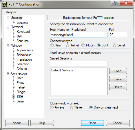
From the other computer, use either PuTTY or ssh if you are on Windows or Mac/Linux respectively.
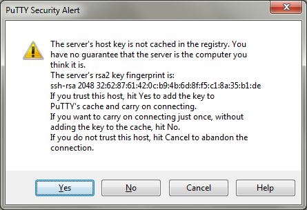
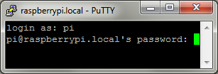
Windows does not resolve .local addresses by default. I believe this is solved if you even have so much as iTunes installed, but if not, you may have to install Bonjour. If you don't want to do that, you can follow the IP address method shown below. Once in putty, simply enter raspberrypi.local in the hostname field, or the IP if the .local name is not working. It will warn you about the fingerprints because you have not connected to this device before. Hit yes and PuTTY will remember this fingerprint for next time and warn you if it changes. Then login as "pi" and use the password "raspberry".
From Linux or a Mac, run the command:
ssh pi@raspberrypi.local
If you can't connect, try using the Raspberry Pi's IP address, which can be found by running the ifconfig command:
pi@raspberrypi ~ $ ifconfig
eth0      Link encap:Ethernet  HWaddr b8:27:eb:5d:a4:c8
          inet addr:192.168.1.101  Bcast:10.0.0.255  Mask:255.255.255.0
          UP BROADCAST RUNNING MULTICAST  MTU:1500  Metric:1
          RX packets:12776 errors:0 dropped:0 overruns:0 frame:0
          TX packets:3604 errors:0 dropped:0 overruns:0 carrier:0
          collisions:0 txqueuelen:1000
RX bytes:12519918 (11.9 MiB) TX bytes:625071 (610.4 KiB)Raspberry Pi Pinout and IO
Raspberry Pi Pinout and IO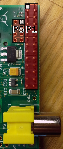 There are some great libraries that make it really easy to use the pins on the Raspberry Pi. It has relatively few pins and are a little less powerful than what you might expect from a microcontroller. Aside from those limitations, you should also keep in mind that pin manipulation is not done in a real time environment. Unlike an Arduino, which only runs your program, the Raspberry Pi takes turns running many programs like a normal desktop. While your program might be able to recieve the majority of the processor's attention, it will not be able to use all of it. Likewise, timing events may be slightly less reliable too. As great as Python is, it is even less reliable because of a process called garbage collection. It is not a problem for most situations, but it is definitely something to keep in mind.
There are two kinds of numbers to specify which pin you want to use. There is the physical pin number, which altenate sideways increasing from top to bottom. For nearly any device, if you look carefully on the board, there is an indicator near the "1" pin on a header. This is even true of integrated circuit (IC) chips. Unlike with ICs, orienting the pins with that indicator in the top left, the pin numbers are increased from left to right and top to bottom. The reason this appears differently on P5 is because the indicator is on the bottom side.
The BCM GPIO number is the number that the processor uses to differentiate the pins. Obviously, pins like 5V and GND cannot be addressed since they only have their one purpose and cannot be changed. As a result, the BCM number is different than the header number. It is important to keep track of which addressing system you are using. It might help you to remember that BCM is a reference to the signal name on the Broadcom datasheet for the processor on the Raspberry Pi.
You should also know that the pinout information only pertains to the revision 2 version of the board. You can tell that you are not using a revision 1 board by the presense fo the P5 holes. P5 was added in revision 2. Revision 1 is essentially the same, but has quite a few pins missing.
| BCM GPIO# | Name | Header | Name | BCM GPIO# | |
|---|---|---|---|---|---|
| 3.3V | 2 | 1 | 5V | ||
| 29 | GPIO9 | 4 | 3 | GPIO8 | 28 |
| 31 | GPIO11 | 6 | 5 | GPIO10 | 20 |
| GND | 8 | 7 | GND | ||
| BCM GPIO# | Name | Header | Name | BCM GPIO# | |
|---|---|---|---|---|---|
| 3.3V | 1 | 2 | 5V | ||
| 2 | SDA* | 3 | 4 | 5V | |
| 3 | SCL* | 5 | 6 | GND | |
| 4 | GPIO7 | 7 | 8 | TX | 14 |
| GND | 9 | 10 | RX | 15 | |
| 17 | GPIO0 | 11 | 12 | PWM0 | 18 |
| 27 | GPIO2 | 13 | 14 | GND | |
| 22 | GPIO3 | 15 | 16 | GPIO4 | 23 |
| 3.3V | 17 | 18 | GPIO5 | 24 | |
| 10 | SPI MOSI | 19 | 20 | GND | |
| 9 | SPI MISO | 21 | 22 | GPIO6 | 25 |
| 11 | SPI SCLK | 23 | 24 | SPI CE0 | 8 |
| GND | 25 | 26 | SPI CE1 | 7 | |
*The i2c pins conveniently have 1.8 kΩ pullup resistors.
Each of these pins have their own limitations:
| Pin Type | Max Current |
|---|---|
| 3.3V | 50mA |
| 5V | 200mA |
| GPIO | 16mA @ 3.3V |
| Total GPIO | 51mA |
| Input High | >1.3V |
| Input Low | <0.8V |
It might be possible that the "total GPIO" and "3.3V" limitations both refer to the same number. Needless to say, in any case you really cannot put much on the GPIO or 3.3V power. Really, it's just two LEDs and you're already at 40-60mA.
Given the voltage and current limits of these pins, you will likely find yourself needing ways around them. A logic level converter is good for interfacing 3.3V serial and GPIO to 5V devices. Shift registers and I/O port expanders are both good for both being able to deliver more current and adding more pins. There are all sorts of ways around these limitations, but simple stuff like MOSFETS, transistors, and voltage regulators can be the most effective. There are also no analog inputs, so to read voltage you can use an Analog to Digital Converter (ADC). One way to get around all of these limitations is to use an ATmega or Arduino for any controls, and just use the Raspberry Pi for anything resource intensive, but interfacing the two still requires a logic level converter since they usually operate at different voltages. There are 3.3V Arduino variants though.
Using the GPIO Pins
GPIO is easily done with the rpi-gpio python package. First, make sure you have it installed by opening a terminal (like LXterminal)
sudo apt-get update
sudo apt-get install python-dev python-rpi.gpio
Then, just make a plain text file using whatever editor you like containing something like this:
import RPi.GPIO as io
import time

io.setmode(io.BCM)
# io.BCM says use the BCM GPIO numbering system for pins.
# io.BOARD will use the actual "header" numbers.

# reading from a GPIO pin
inputPinNumber = 18                     # the BCM GPIO pin number, 12 if io.BOARD
io.setup(inputPinNumber, io.IN)         # similar to pinMode in Arduino
if io.input(inputPinNumber):            # read the pin, use in if condition
    print("Pin 18 is high")
else:
    print("Pin 18 is low")

# writting to a GPIO pin
outputPinNumber = 23                    # the BCM GPIO pin number, 16 if io.BOARD
io.setup(outputPinNumber, io.OUT)
while True:                             # loop forever
    io.output(outputPinNumber, io.HIGH) # set the pin output to high (3.3V)
    time.sleep(0.5)                     # wait a half a second
    io.output(outputPinNumber, io.LOW)  # set the pin output to low (0V)
    time.sleep(0.5)                     # wait another half a second before looping
You will need to run it as root, since GPIO manipulation requires root priviliges.
pi@raspberrypi ~ $ sudo python pinIOtest.py
Using i2C and SPI
These serial connections require a little more setup because they require kernel modules, which are like drivers. They disabled them by default because "many users don't need them". I guess we are one of the few, huh?
You can copy these lines to a terminal like LXterminal or in SSH. The stuff after the # is just comments to explain what they do. You don't need to retype it, but it won't hurt if you're copy and pasting either.
sudo rm /etc/modprobe.d/raspi-blacklist.conf # remove their "disable"
sudo modprobe i2c-bcm2708 i2c-dev            # enable modules now without restart
echo i2c-bcm2708 | sudo tee /etc/modules     # add the i2c driver to startup
echo i2c-dev | sudo tee /etc/modules         # add other i2c driver to startup
sudo apt-get install python-smbus i2c-tools  # install some useful i2c tools
Now you can see what's connected to i2c with this neat command:
pi@raspberrypi ~ $ sudo i2cdetect -y 1
     0  1  2  3  4  5  6  7  8  9  a  b  c  d  e  f
00:          -- -- -- -- -- -- -- -- -- -- -- -- --
10: -- -- -- -- -- -- -- -- -- -- -- -- -- -- -- --
20: 20 -- -- -- -- -- -- -- -- -- -- -- -- -- -- --
30: -- -- -- -- -- -- -- -- -- -- -- -- -- -- -- --
40: -- -- -- -- -- -- -- -- -- -- -- -- -- -- -- --
50: -- -- -- -- -- -- -- -- -- -- -- -- -- -- -- --
60: -- -- -- -- -- -- -- -- -- -- -- -- -- -- -- --
70: -- -- -- -- -- -- -- --
The output shows that there is a device connected to the i2c bus and has an address of 20. This is the default address for an MCP230 port expander, which is what I have hooked up to it. If nothing were hooked up to the SCL and SDA that was i2c compatible, there would be "--" there, just like everything else.
Now, to use i2c in a Python program, use the SMBus package:
import smbus
bus = smbus.SMBus(1)
address = 0x20
write_byte(addr,val)
read_byte(addr)
Syncing Files on the Raspberry Pi
Syncing Files on the Raspberry PiIntroduction
Syncing files automatically from a Raspberry Pi is a good idea to make sure that nothing gets lost the Pi breaks. The problem is that due to the unusual ARM architecture, most of the common methods for syncing are not available. Dropbox does not have an ARM package. Google Drive never had a Linux client. There are ways around these limitations either by use of lower quality third party applications to interface with the major sync solutions or by use of open source and self hosted solutions.
Sparkleshare
Sparkleshare is a self-hosted solution. Sparkleshare uses Git on its backend, so it's particularly good for text files. You can also use a git host like Bitbucket. It provides an easy to use graphical interface and is very easy to set up
On the Raspberry Pi:
pi@raspberrypi:~# sudo apt-get install sparkleshare
Building Sparkleshare (unnecessary if using the package from apt-get):
#install all mono stuff, which is probably (definitely) overkill
pi@raspberrypi:~# sudo apt-get install libmono-2.0-dev mono-complete gtk-sharp2 libwebkit-cil-dev libnotify0.4-cil libnotify-cil-dev
pi@raspberrypi:~# mkdir apps ; cd apps
pi@raspberrypi:~# wget <getrecentlink>.tar.gz
pi@raspberrypi:~# tar -xzf sparkleshare-linux-1.1.0-tar.gz
pi@raspberrypi:~# cd sparkleshare-1.1.0/
pi@raspberrypi:~# ./configure
pi@raspberrypi:~# make
pi@raspberrypi:~# sudo make install
On your "host" computer (unnecessary if using third party Git host)
root@evan-ubuntu:~# sudo su && cd
# Fetch the Dazzle script
root@evan-ubuntu:~# curl https://raw.github.com/hbons/Dazzle/master/dazzle.sh \
  --output /usr/bin/dazzle && chmod +x /usr/bin/dazzle
# Run the initial setup
root@evan-ubuntu:~# dazzle setup
# Link SparkleShare clients using their Client ID found in the status menu
root@desktop:~# dazzle link
Paste your Client ID (found in the status icon menu) below and press <ENTER>.

 Client ID:  ssh-rsa AAAAB3NzaC1yc2EAAAADAQ... ... ...TnTL4SK1+7gYKT raspberrypi

# Create a new project. Add as many as you need
root@evan-ubuntu:~# dazzle create raspberry # raspbery project or directory name
Project "raspberry" was successfully created.
To link up a SparkleShare client, enter the following
details into the "Add Hosted Project..." dialog:

      Address: ssh://storage@evan-ubuntu.local
  Remote Path: /home/storage/raspberry
Setup on the client side uses a GUI:
pi@raspberrypi:~# DISPLAY=:0 sparkleshare start


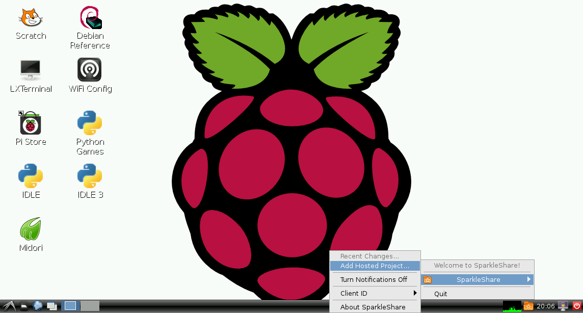

Grive
Grive is the unnofficial Google Drive client for Linux. Google has no official linux client, but in this specific case that is actually a good thing, in a weird way, because the open source version can be built from source and can run on the Raspberry Pi's ARM processor.
First, try installing from the repos. In a lot of debian archives, grive is now available. At the point of writting this though, it is not currenlty in the Raspbian repo, but is in other Debian repos.
pi@raspberrypi ~ $ sudo apt-get install grive
Building Grive from Source
If that package does not work, you can build it from source, but it takes a really long time to build.
This will add quite a few packages to your Raspbian - a couple hundred MB worth, which takes more than a couple minutes to install. The build also takes about 20 minutes.
sudo apt-get install cmake git build-essential libgcrypt11-dev libjson0-dev libcurl4-openssl-dev libexpat1-dev libboost-filesystem-dev libboost-program-options-dev binutils-dev libqt4-core libqt4-dev libboost-test-dev libboost-filesystem-dev libboost-program-options-dev libboost-system-dev libyajl-dev

pi@raspberrypi $ mkdir ~/apps ; cd ~/apps
pi@raspberrypi ~/apps $ git clone git://github.com/Grive/grive.git
pi@raspberrypi ~/apps $ cd grive
pi@raspberrypi ~/apps/grive $ cmake .
-- Found libgcrypt: -L/lib/arm-linux-gnueabihf -lgcrypt
-- Found JSON-C: /usr/lib/arm-linux-gnueabihf/libjson.so
-- Boost version: 1.49.0
-- Found the following Boost libraries:
--   program_options
--   filesystem
--   unit_test_framework
--   system
-- Found libbfd: /usr/lib/libbfd.so
-- Found libiberty: /usr/lib/libiberty.a
-- Boost version: 1.49.0
-- Found the following Boost libraries:
--   program_options
-- Boost version: 1.49.0
-- Configuring done
-- Generating done
-- Build files have been written to: /home/pi/apps/grive
If you do not add these scope resolution operators, the compiler does not seem to know to use the Boost library. It might also have to do with the sizes of variables on the ARM processor versus normal.
pi@raspberrypi ~/apps/grive $ nano libgrive/src/drive/State.cc
void State::Write( const fs::path& filename ) const
{
        Json last_sync ;

        last_sync.Add( "sec", Json((boost::uint64_t) m_last_sync.Sec() ) );
        last_sync.Add( "nsec", Json((boost::uint64_t) m_last_sync.NanoSec() ) );

        //last_sync.Add( "sec", Json(m_last_sync.Sec() ) );
        //last_sync.Add( "nsec",        Json(m_last_sync.NanoSec() ) );

        Json result ;
        result.Add( "last_sync", last_sync ) ;

        //result.Add( "change_stamp", Json(m_cstamp) ) ;
        result.Add( "change_stamp", Json((boost::uint64_t) m_cstamp) ) ;

        std::ofstream fs( filename.string().c_str() ) ;
        fs << result ;
}
Now that you've patched it a little bit, you can actually build it. This takes a while.
pi@raspberrypi ~/apps/grive $ make
[  1%] Building CXX object libgrive/CMakeFiles/grive.dir/src/json/JsonParser.cc.o
/tmp/ccN9aaS9.s: Assembler messages:
/tmp/ccN9aaS9.s:1258: Warning: swp{b} use is deprecated for this architecture
[  3%] Building CXX object libgrive/CMakeFiles/grive.dir/src/json/ValBuilder.cc.o
/tmp/cc0qtdOv.s: Assembler messages:
/tmp/cc0qtdOv.s:1317: Warning: swp{b} use is deprecated for this architecture
[  5%] Building CXX object libgrive/CMakeFiles/grive.dir/src/json/JsonWriter.cc.o
[  7%] Building CXX object libgrive/CMakeFiles/grive.dir/src/json/ValResponse.cc.o
[  8%] Building CXX object libgrive/CMakeFiles/grive.dir/src/util/File.cc.o
/tmp/ccCrhkFO.s: Assembler messages:
/tmp/ccCrhkFO.s:1317: Warning: swp{b} use is deprecated for this architecture
[ 10%] Building CXX object libgrive/CMakeFiles/grive.dir/src/util/Config.cc.o
[ 12%] Building CXX object libgrive/CMakeFiles/grive.dir/src/util/StdStream.cc.o
[ 14%] Building CXX object libgrive/CMakeFiles/grive.dir/src/util/Exception.cc.o
/tmp/cca93GMZ.s: Assembler messages:
/tmp/cca93GMZ.s:1298: Warning: swp{b} use is deprecated for this architecture
[ 16%] Building CXX object libgrive/CMakeFiles/grive.dir/src/util/OS.cc.o
/tmp/cchdH7ge.s: Assembler messages:
/tmp/cchdH7ge.s:1258: Warning: swp{b} use is deprecated for this architecture
[ 17%] Building CXX object libgrive/CMakeFiles/grive.dir/src/util/DateTime.cc.o
/tmp/ccnsT4HV.s: Assembler messages:
/tmp/ccnsT4HV.s:1258: Warning: swp{b} use is deprecated for this architecture
[ 19%] Building CXX object libgrive/CMakeFiles/grive.dir/src/util/StringStream.cc.o
[ 21%] Building CXX object libgrive/CMakeFiles/grive.dir/src/util/SignalHandler.cc.o
[ 23%] Building CXX object libgrive/CMakeFiles/grive.dir/src/util/Crypt.cc.o
/tmp/ccx344KH.s: Assembler messages:
/tmp/ccx344KH.s:1258: Warning: swp{b} use is deprecated for this architecture
[ 25%] Building CXX object libgrive/CMakeFiles/grive.dir/src/util/MemMap.cc.o
[ 26%] Building CXX object libgrive/CMakeFiles/grive.dir/src/util/log/CompositeLog.cc.o
[ 28%] Building CXX object libgrive/CMakeFiles/grive.dir/src/util/log/DefaultLog.cc.o
[ 30%] Building CXX object libgrive/CMakeFiles/grive.dir/src/util/log/CommonLog.cc.o
[ 32%] Building CXX object libgrive/CMakeFiles/grive.dir/src/util/log/Log.cc.o
[ 33%] Building CXX object libgrive/CMakeFiles/grive.dir/src/xml/String.cc.o
[ 35%] Building CXX object libgrive/CMakeFiles/grive.dir/src/xml/NodeSet.cc.o
/tmp/ccshU8Rr.s: Assembler messages:
/tmp/ccshU8Rr.s:1284: Warning: swp{b} use is deprecated for this architecture
[ 37%] Building CXX object libgrive/CMakeFiles/grive.dir/src/xml/Node.cc.o
/tmp/cc03tDy6.s: Assembler messages:
/tmp/cc03tDy6.s:1284: Warning: swp{b} use is deprecated for this architecture
[ 39%] Building CXX object libgrive/CMakeFiles/grive.dir/src/xml/TreeBuilder.cc.o
/tmp/ccEaKl2M.s: Assembler messages:
/tmp/ccEaKl2M.s:1258: Warning: swp{b} use is deprecated for this architecture
[ 41%] Building CXX object libgrive/CMakeFiles/grive.dir/src/bfd/Debug.cc.o
[ 42%] Building CXX object libgrive/CMakeFiles/grive.dir/src/bfd/SymbolInfo.cc.o
[ 44%] Building CXX object libgrive/CMakeFiles/grive.dir/src/bfd/Backtrace.cc.o
Linking CXX static library libgrive.a
[ 82%] Built target grive
Scanning dependencies of target btest
[ 83%] Building CXX object libgrive/CMakeFiles/btest.dir/test/btest/UnitTest.cc.o
[ 85%] Building CXX object libgrive/CMakeFiles/btest.dir/test/btest/ValTest.cc.o
/tmp/ccK8TOeR.s: Assembler messages:
/tmp/ccK8TOeR.s:1331: Warning: swp{b} use is deprecated for this architecture
[ 87%] Building CXX object libgrive/CMakeFiles/btest.dir/test/btest/JsonValTest.cc.o
/tmp/ccOAUEHb.s: Assembler messages:
/tmp/ccOAUEHb.s:1331: Warning: swp{b} use is deprecated for this architecture
Linking CXX executable btest
[ 87%] Built target btest
Scanning dependencies of target grive_executable
Linking CXX executable grive
[ 89%] Built target grive_executable
[ 91%] Generating src/moc_MainWnd.cxx
[ 92%] Generating ui_MainWindow.h
Scanning dependencies of target bgrive_executable
[ 94%] Building CXX object bgrive/CMakeFiles/bgrive_executable.dir/src/DriveModel.cc.o
/tmp/ccgDURnf.s: Assembler messages:
/tmp/ccgDURnf.s:1731: Warning: swp{b} use is deprecated for this architecture
[ 96%] Building CXX object bgrive/CMakeFiles/bgrive_executable.dir/src/MainWnd.cc.o
[ 98%] Building CXX object bgrive/CMakeFiles/bgrive_executable.dir/src/main.cc.o
[100%] Building CXX object bgrive/CMakeFiles/bgrive_executable.dir/src/moc_MainWnd.cxx.o
Linking CXX executable bgrive
[100%] Built target bgrive_executable
Well, now that that's over, the install process seems to need an extra doc, so we'll just add an empty one, which might not be necessary.
pi@raspberrypi ~/apps/grive $ mkdir /home/pi/apps/grive/bgrive/doc/
pi@raspberrypi ~/apps/grive $ touch /home/pi/apps/grive/bgrive/doc/grive.1
pi@raspberrypi ~/apps/grive $ sudo make install
Usage
First, set up a folder to sync your stuff to. Then you open a long authentication link in a browser and log in to your Google account. It will then give you a long code to copy back to the program. It is important that your current directory is the directory you wish to sync with your Google Drive before you do this.
pi@raspberrypi ~ $ mkdir ~/gdrive/ ; cd ~/gdrive
pi@raspberrypi ~/gdrive $ grive -a
-----------------------
Please go to this URL and get an authentication code:

https://accounts.google.com/o/oauth2/auth?scope=............

-----------------------
Please input the authentication code here:
XXXXXXXXXXXXXXXXXXXXXXXXXXXXXXXXXXXXXXXXXXXXXXXXXXXXXXXXXXXXXX
Reading local directories
Synchronizing folders
Reading remote server file list
Synchronizing files
... ... ... ...
Now, to set up automatic sync, it unfortunately has to be done this somewhat simplistic way:
pi@raspberrypi ~ $ mkdir ~/bin/
pi@raspberrypi ~ $ echo "#! /bin/bash
> cd ~/gdrive/
> grive" > ~/bin/gsync
pi@raspberrypi ~ $ chmod +x ~/bin/gysnc
pi@raspberrypi ~ $ crontab -e
*/10 * * * * /home/pi/bin/gsync
Now, your Google Drive will sync to your to your Raspberry Pi every 10 minutes. There might be a way to do this every time a file changes on the Raspberry Pi using inotifywait, but it would not sync changes from Google Drive until there is a change locally.
dropfuse
Dropfuse is not one of the best or most secure options, but Dropbox is a really nice service. Dropfuse is a third party script that relies on the "share link" feature. It does not actually connect to your entire Dropbox account. It will only connect to a single shared folder. Log onto dropbox.com, navigate to the folder you want sync'd and click "share link". You'll find a link like this:
https://www.dropbox.com/sh/AAAAAAAAAAAAAAA/BBBBBBBBBB
Modify the link yourself to this format:
https://www.dropbox.com/s/AAAAAAAAAAAAAAA
The install process is relatively easy.
pi@raspberrypi ~ $ sudo apt-get install python-pyquery
pi@raspberrypi ~ $ sudo usermod -a -G fuse pi
pi@raspberrypi ~ $ mkdir apps
pi@raspberrypi ~ $ mkdir Dropbox
pi@raspberrypi ~ $ cd apps
pi@raspberrypi ~/apps $ git clone git://github.com/arekzb/dropfuse.git
Cloning into 'dropfuse'...
remote: Counting objects: 38, done.
remote: Compressing objects: 100% (21/21), done.
remote: Total 38 (delta 19), reused 34 (delta 17)
Receiving objects: 100% (38/38), 14.16 KiB, done.
Resolving deltas: 100% (19/19), done.
pi@raspberrypi ~/apps $ cd dropfuse
sudo python dropfuse.py https://www.dropbox.com/s/c6ecc2plwconh5x ~/Dropbox &
To stop the service, do this:
pi@raspberrypi ~ $ fusermount -u Dropbox
BitTorrent Sync
A word of warning, btsync causes lots of networking issues. On an Ubuntu machine, it can cause 10% of your dns queries to timeout. The symptoms are less severe on a Windows computer, but still problematic for seemingly anything but web browsing, which seems unaffected. I cannot recommend BitTorrent Sync as a result, but maybe they will have patched it by the time you are reading this, so here goes.
In concept, this might be the best of any of the options. It is distributed and peer to peer. It deals with binary files well. You can share over the internet without DNS or public IPs. It is extremely simple to set up, despite what all is going on under the hood.
wget http://btsync.s3-website-us-east-1.amazonaws.com/btsync_arm.tar.gz
tar xzf btsync_arm.tar.gz
rm btsync_arm.tar.gz LICENSE.TXT
sudo ln -s /lib/arm-linux-gnueabihf/ld-linux.so.3 /lib/ld-linux.so.3
./btsync
Then just take a browser and visit http://raspberrypi.local:8888/.
BeagleBone
BeagleBoneIntroduction
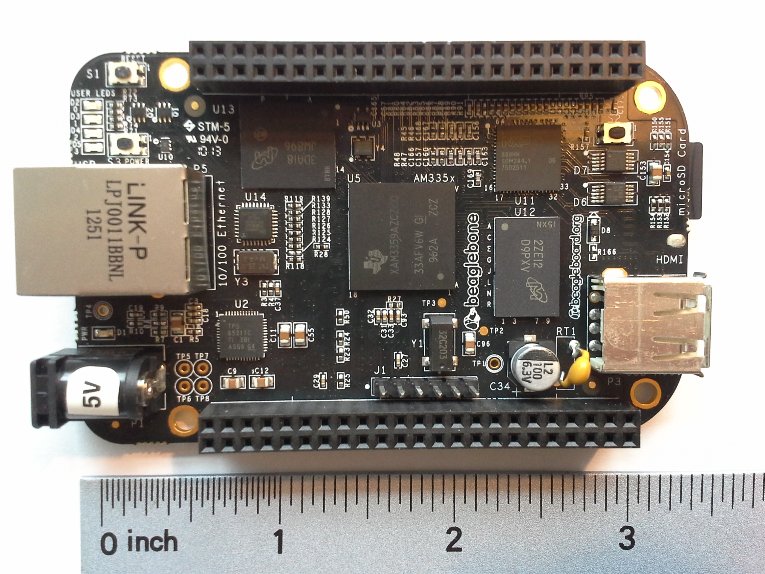 The BeagleBone is like a combination between a microcontroller (like Arduino) and a small Linux desktop. It is most similar to a Raspberry Pi, but with more pinouts and a faster processor. The BeagleBone has several variants, the most recent edition being the BeagleBone Black (aka BBB), which retails for $45 USD.
It is a great choice if you are going to add image or video processing to your robot. An Arduino is nowhere near powerful enough to handle images. Arduino, however, is extremely easy to use and extremely well documented with a massive community.
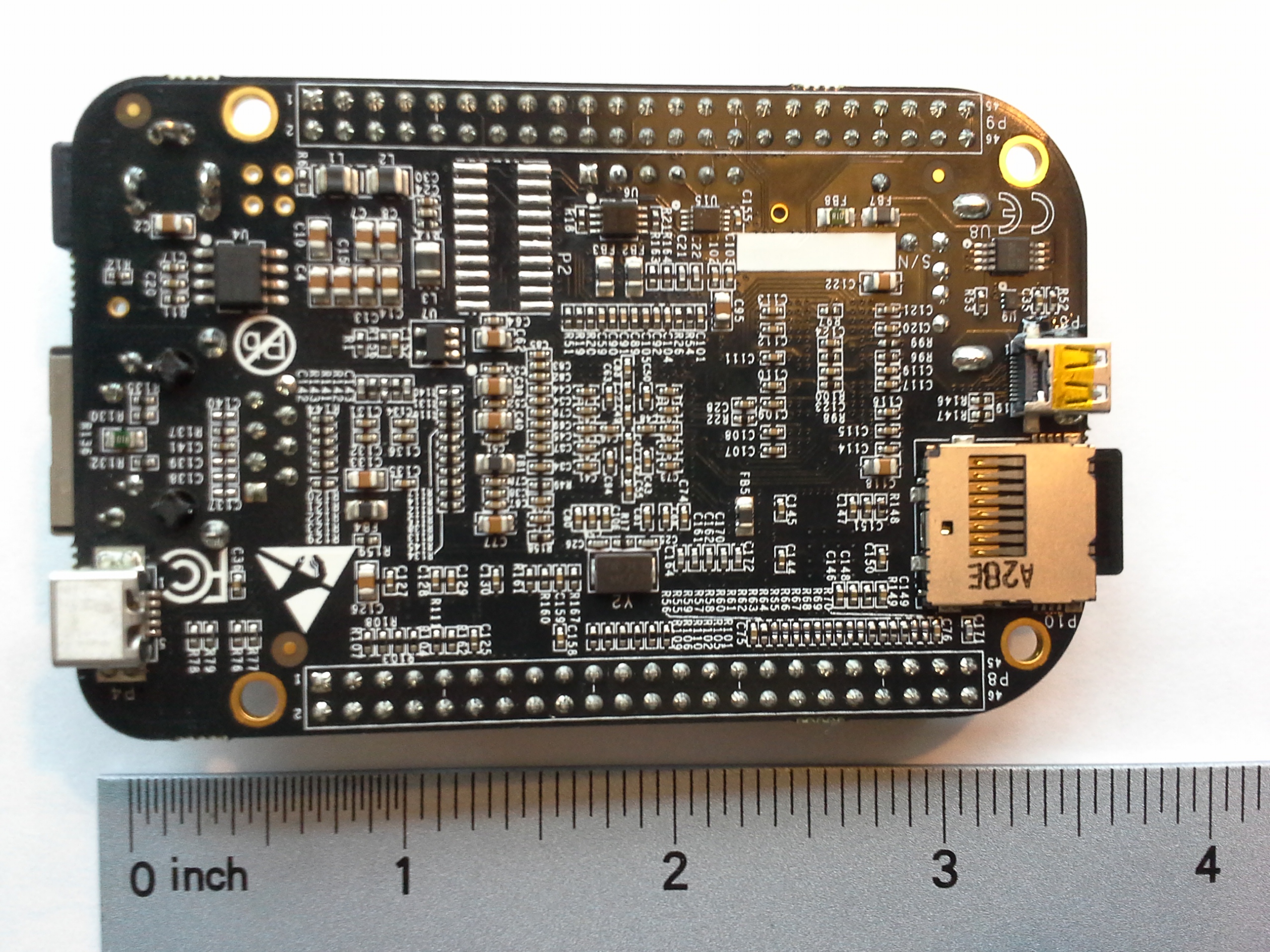 Against a Raspberry Pi, it's a harder choice to make. It's more expensive, but has a processor that's faster and capable of running ARMv7 operating systems like Ubuntu and Android, where a Raspberry Pi is substantially more limited. A Raspberry Pi is easier to use and has a much larger community behind it, but the BeagleBone has some powerful hardware features. If you are undecided, the good news is that they are both really cheap, both run Python, and have very similar ways of accessing GPIO (the /sys/ directory), so really you could change your mind midway through a project and not face too much of a setback.
BeagleBone Black with Angstrom
BeagleBone Black with AngstromIntroduction
Angstrom Linux is what ships on the BeagleBones. It's kind of terrible because I think everyone when they first get it will say, oh I should run opkg upgrade so that everything is up to date. Guess what? That breaks the boot. It won't startup anymore. I don't know how to fix it or what goes wrong. You'll get three LED's on, no USB connection on either the mass media or network, and it'll never come online on the LAN because it won't start up.
If you want things to be up to date, you may want to install Ubuntu.
On the other hand, it is pretty lightweight and is pre-configured in a lot of ways that other distros don't have by default. For example, the cloud9 editor is kind of nice.
Installing Images
Whether you have a BeagleBone or BeagleBone Black, you can use the Angstrom-Cloud9-IDE-GNOME-eglibc-ipk*.img.xz
They both run ARM7 and the image has the NEON optimization. The image for the BeagleBone Black might have additional features, but it's the same Angstrom with less features as far as I can tell.
sudo su
xz -cd ./Angstrom-Cloud9-IDE-GNOME-****.img.xz > /dev/sdd
URLs
Check out the tutorial page on http://beaglebone.local/. There are some neat node.js buttons on http://beaglebone.local/bonescript.html
The very cool Cloud9 IDE is available on http://beaglebone.local:3000/.
If you're on windows and don't have an SSH client that you like, there's GateOne SSH client availble in-browser at https://beaglebone.local/
If those URLs don't work, then you might try replacing beaglebone.local with 192.168.7.2. If that doesn't work, there might be something wrong with your installation. You could re-flash another image.
Tweaks
Disable GNOME autostart
If you want a graphical environment to develop and test on, that's fine, but a lot of the time your deployment will be headless. Well, you can have your cake and eat it too.
update-rc.d -f gdm remove
systemctl disable gdm
mv /lib/systemd/system/gdm.service ~/gdm.backup.service
systemctl --system daemon-reload
There are probably more steps there than are necessary, but I couldn't get it to stay down for a while, so try them all.
Then if you want to start your graphical environment at any point, just login and run gdm
Install locate
Locate is an awesome tool for searching the filesystem really quickly.
opkg install findutils
updatedb
Run a Script on Startup (cron)
nano ~/startup.sh
#put something in /tmp/ so we can see if this ran
touch /tmp/WINNING
#turn off the heartbeat
echo 0 > /sys/class/leds/beaglebone\:green\:usr0/brightness
chmod +x ~/startup.sh
env EDITOR=nano crontab -e
@reboot /bin/bash /home/root/startup.sh
Run a Script on Startup (systemd)
Angstrom uses systemd, so it has a few things different than a Debian/Ubuntu system. Not sure why you'd want to do it this way. It's a lot harder than cron.
First make a script you want to run on startup. You might just use this bash file to launch all your other processes. If you do, throw a & at the end of each line to run them in background.
nano ~/mystartup.sh
#!/bin/bash
touch /tmp/WINNING
chmod +x ~/mystartup.sh
After making an executable script, make a service for systemd to use.
nano /lib/systemd/system/mystartup.service
[Unit]
Description=My own script to run on startup
ConditionPathExists=|/usr/bin
After=local-fs.target

[Service]
Type=oneshot
ExecStart=/home/root/mystartup.sh
systemctl --system daemon-reload
systemctl enable mystartup.service
To load it and test it, try:
systemctl start mystartup.service
ls -l /tmp/WINNING
journalctl
Note that journalctl is apparently the new way of doing a "less /var/log/syslog"
Benchmarks
Compare the benchmarks to those of the Raspberry Pi (wiki) using this package (zip). Also compare to my Ubuntu BBB tests.
Processor Info
root@beaglebone:~# cat /proc/cpuinfo
processor	: 0
model name	: ARMv7 Processor rev 2 (v7l)
BogoMIPS	: 990.68
Features	: swp half thumb fastmult vfp edsp thumbee neon vfpv3 tls
CPU implementer	: 0x41
CPU architecture: 7
CPU variant	: 0x3
CPU part	: 0xc08
CPU revision	: 2

Hardware	: Generic AM33XX (Flattened Device Tree)
Revision	: 0000
Serial		: 0000000000000000
Dhrystone
At 3059570 dhrystones per second, the BBB with Angstrom is almost 4 times faster than a Raspberry Pi (809061) with Raspbian on it. However, it is about 10% slower than it could be with Ubuntu on it (3319960).
##########################################

Dhrystone Benchmark, Version 2.1 (Language: C or C++)
Optimisation    Opt 3 32 Bit
Register option not selected

       10000 runs   0.01 seconds
      100000 runs   0.11 seconds
      200000 runs   0.18 seconds
      400000 runs   0.13 seconds
      800000 runs   0.26 seconds
     1600000 runs   0.52 seconds
     3200000 runs   1.05 seconds
     6400000 runs   2.09 seconds

Final values (* implementation-dependent):

Int_Glob:      O.K.  5  Bool_Glob:     O.K.  1
Ch_1_Glob:     O.K.  A  Ch_2_Glob:     O.K.  B
Arr_1_Glob[8]: O.K.  7  Arr_2_Glob8/7: O.K.     6400010
Ptr_Glob->              Ptr_Comp:       *    94584
  Discr:       O.K.  0  Enum_Comp:     O.K.  2
  Int_Comp:    O.K.  17 Str_Comp:      O.K.  DHRYSTONE PROGRAM, SOME STRING
Next_Ptr_Glob->         Ptr_Comp:       *    94584 same as above
  Discr:       O.K.  0  Enum_Comp:     O.K.  1
  Int_Comp:    O.K.  18 Str_Comp:      O.K.  DHRYSTONE PROGRAM, SOME STRING
Int_1_Loc:     O.K.  5  Int_2_Loc:     O.K.  13
Int_3_Loc:     O.K.  7  Enum_Loc:      O.K.  1
Str_1_Loc:                             O.K.  DHRYSTONE PROGRAM, 1'ST STRING
Str_2_Loc:                             O.K.  DHRYSTONE PROGRAM, 2'ND STRING


From File /proc/cpuinfo
processor	: 0
model name	: ARMv7 Processor rev 2 (v7l)
BogoMIPS	: 297.40
Features	: swp half thumb fastmult vfp edsp thumbee neon vfpv3 tls
CPU implementer	: 0x41
CPU architecture: 7
CPU variant	: 0x3
CPU part	: 0xc08
CPU revision	: 2

Hardware	: Generic AM33XX (Flattened Device Tree)
Revision	: 0000
Serial		: 0000000000000000


From File /proc/version
Linux version 3.8.13 (koen@rrMBP) (gcc version 4.7.3 20130205 (prerelease) (Linaro GCC 4.7-2013.02-01) ) #1 SMP Mon May 20 17:07:58 CEST 2013


Nanoseconds one Dhrystone run:       326.84
Dhrystones per Second:              3059570
VAX  MIPS rating =                  1741.36
OpenSSL
Again, the BBB on Angstrom proves to be significantly faster than the Raspberry Pi. About 4 times faster or way more. However, the comparison to the BBB with Ubuntu are actually the opposite. Angstrom is faster by about 10%. The difference? No NEON FPU optimizations on Ubuntu!
root@beaglebone:~# openssl speed;
OpenSSL 1.0.0j 10 May 2012
built on: Wed Apr  3 21:06:55 CEST 2013
options:bn(64,32) rc4(ptr,int) des(idx,risc1,2,long) aes(partial) idea(int) blowfish(idx)
compiler: arm-angstrom-linux-gnueabi-gcc  -march=armv7-a     -mthumb-interwork -mfloat-abi=softfp -mfpu=neon -mtune=cortex-a8 --sysroot=/build/v2012.12/build/tmp-angstrom_v2012_12-eglibc/sysroots/olinuxino-a13 -fPIC -DOPENSSL_PIC -DOPENSSL_THREADS -D_REENTRANT -DDSO_DLFCN -DHAVE_DLFCN_H -DL_ENDIAN 	-DTERMIO -O2 -pipe -g -feliminate-unused-debug-types -Wall -DHAVE_CRYPTODEV -DUSE_CRYPTODEV_DIGESTS
The 'numbers' are in 1000s of bytes per second processed.
type             16 bytes     64 bytes    256 bytes   1024 bytes   8192 bytes
md2                  0.00         0.00         0.00         0.00         0.00
mdc2              2200.18k     2903.10k     3079.22k     3123.71k     3131.59k
md4               5415.82k    20091.55k    62372.30k   131555.57k   194939.46k
md5               4617.55k    16804.97k    50871.15k   102349.66k   145803.90k
hmac(md5)         7419.73k    25105.91k    67753.84k   117279.85k   149212.21k
sha1              4689.06k    15086.80k    37111.10k    58582.77k    70082.56k
rmd160            4321.96k    13657.71k    33189.03k    51514.42k    61322.19k
rc4              51274.46k    57055.08k    58599.86k    59068.36k    59196.82k
des cbc          15641.44k    16844.09k    17096.95k    17186.71k    17143.13k
des ede3          5966.27k     6118.46k     6149.65k     6173.80k     6179.74k
idea cbc         15220.99k    16040.11k    16331.43k    16378.86k    16340.16k
seed cbc         21797.27k    23300.32k    23793.27k    23880.09k    23956.81k
rc2 cbc          13306.59k    14101.91k    14234.37k    14302.09k    14325.00k
rc5-32/12 cbc        0.00         0.00         0.00         0.00         0.00
blowfish cbc     27004.49k    29706.03k    30572.82k    30746.37k    30866.58k
cast cbc         26993.30k    29720.81k    30501.50k    30798.77k    30854.70k
aes-128 cbc      27466.35k    29851.57k    30765.55k    31029.95k    31033.71k
aes-192 cbc      23934.83k    25819.16k    26408.67k    26625.71k    26651.49k
aes-256 cbc      21310.20k    22657.92k    23204.56k    23356.48k    23362.27k
camellia-128 cbc    28544.43k    31191.34k    31965.01k    32352.21k    32362.51k
camellia-192 cbc    23092.30k    24841.16k    25474.06k    25586.30k    25650.86k
camellia-256 cbc    23167.57k    24852.70k    25346.39k    25612.71k    25614.38k
sha256            4648.14k    11368.65k    21020.95k    26654.38k    29045.86k
sha512             969.92k     3858.49k     5574.64k     7650.79k     8548.17k
whirlpool         1872.39k     3901.80k     6372.60k     7553.37k     7996.82k
aes-128 ige      25801.92k    28261.82k    29148.35k    29319.28k    28924.91k
aes-192 ige      22733.70k    24548.07k    25245.12k    25323.28k    25036.29k
aes-256 ige      20328.61k    21757.95k    22204.79k    22366.69k    22090.91k
                  sign    verify    sign/s verify/s
rsa  512 bits 0.002286s 0.000191s    437.4   5244.1
rsa 1024 bits 0.011637s 0.000559s     85.9   1790.5
rsa 2048 bits 0.068425s 0.001828s     14.6    546.9
rsa 4096 bits 0.444783s 0.006260s      2.2    159.7
                  sign    verify    sign/s verify/s
dsa  512 bits 0.001946s 0.002152s    513.9    464.7
dsa 1024 bits 0.005539s 0.006413s    180.5    155.9
dsa 2048 bits 0.018094s 0.021652s     55.3     46.2
                              sign    verify    sign/s verify/s
 160 bit ecdsa (secp160r1)   0.0011s   0.0048s    935.6    210.4
 192 bit ecdsa (nistp192)   0.0011s   0.0052s    873.1    192.9
 224 bit ecdsa (nistp224)   0.0015s   0.0069s    679.8    144.8
 256 bit ecdsa (nistp256)   0.0020s   0.0099s    509.9    100.8
 384 bit ecdsa (nistp384)   0.0041s   0.0218s    245.0     45.8
 521 bit ecdsa (nistp521)   0.0093s   0.0490s    107.4     20.4
 163 bit ecdsa (nistk163)   0.0040s   0.0081s    247.2    124.2
 233 bit ecdsa (nistk233)   0.0078s   0.0154s    128.3     65.1
 283 bit ecdsa (nistk283)   0.0119s   0.0276s     84.3     36.2
 409 bit ecdsa (nistk409)   0.0283s   0.0632s     35.3     15.8
 571 bit ecdsa (nistk571)   0.0634s   0.1443s     15.8      6.9
 163 bit ecdsa (nistb163)   0.0040s   0.0087s    252.3    115.5
 233 bit ecdsa (nistb233)   0.0076s   0.0166s    130.8     60.3
 283 bit ecdsa (nistb283)   0.0118s   0.0302s     84.6     33.2
 409 bit ecdsa (nistb409)   0.0284s   0.0718s     35.2     13.9
 571 bit ecdsa (nistb571)   0.0637s   0.1660s     15.7      6.0
                              op      op/s
 160 bit ecdh (secp160r1)   0.0041s    246.8
 192 bit ecdh (nistp192)   0.0044s    229.8
 224 bit ecdh (nistp224)   0.0057s    174.7
 256 bit ecdh (nistp256)   0.0083s    121.1
 384 bit ecdh (nistp384)   0.0177s     56.6
 521 bit ecdh (nistp521)   0.0406s     24.6
 163 bit ecdh (nistk163)   0.0039s    255.5
 233 bit ecdh (nistk233)   0.0075s    132.8
 283 bit ecdh (nistk283)   0.0136s     73.6
 409 bit ecdh (nistk409)   0.0312s     32.1
 571 bit ecdh (nistk571)   0.0718s     13.9
 163 bit ecdh (nistb163)   0.0042s    236.7
 233 bit ecdh (nistb233)   0.0082s    121.3
 283 bit ecdh (nistb283)   0.0152s     65.7
 409 bit ecdh (nistb409)   0.0357s     28.0
 571 bit ecdh (nistb571)   0.0825s     12.1
BeagleBone Black with Ubuntu
BeagleBone Black with UbuntuIntroduction
The BeagleBone Black is a very powerful and affordable microcontroller - superior to an Arduino Uno in a lot of ways. It's fast enough to be used as a desktop computer, yet it has more pinouts than an Uno. With the BeagleBone Black priced at $45, it's really a great value compared to an Arduino ($35) or even a Raspberry Pi ($35).
An Arduino, while power-efficient and reliable, is incapable of high performance use cases like image processing. Even the ARM based Arduino Due is thousands of times slower than the BeagleBone Black. It can't even parse a JPEG (the library won't fit in the flash). A BeagleBone or Raspberry Pi, however, can easily process live streams from USB webcams and OpenCV.
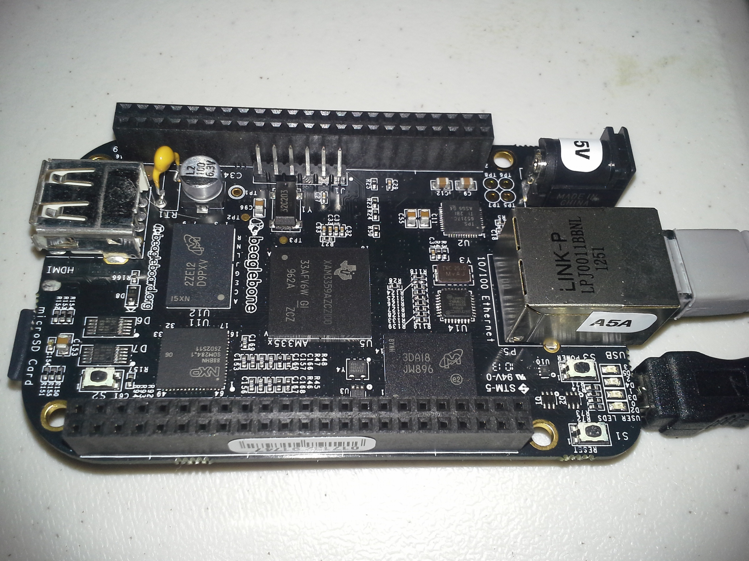 The BeagleBone Black is significantly faster and more capable than the comperable $35 Raspberry Pi Model B. Both have the same RAM, HDMI out, and Ethernet, but the BeagleBone Black has superior IO (more and faster) and has a faster processor capable of running Ubuntu, where the Raspberry Pi cannot due to its older architecture. Remember, Raspberry Pi was intended to be an educational tool to teach kids to program, not to help you hack together a robot. The BBB has two extra processors dedicated to effectively manage the pinouts.
The downside? The pre-installed OS (Angstrom) at this point in time will break if you do a package upgrade. Not only will it never boot again once it finishes updating, but it also uses too much of the /tmp/ filesystem and stalls halfway though. You can run Ubuntu on it, but there isn't much of a point, since it's basically incapable of having a desktop UI or using OpenGL as far as I can tell. There's no reason why it shouldn't be possible. In fact, LXDE and XFCE sort of work. This leads to the bigger problem. The documentation, support, and community behind BeagleBone is nowhere near that of the Raspberry Pi, let alone Arduino (which has the best by far).
Setup
A lof of this information is based on the BeagleBone Ubuntu wiki.
Installing to an SD Card
From a Linux computer that has the target microSD card in, download a recent .tar.xz from this wiki or our upload of the 13.04 image, in case theirs disappears. Then run these bash commands:
tar xJf ubuntu-13.04-console-armhf-2013-05-18.tar.xz
cd ubuntu-13.04-console-armhf-2013-05-18
sudo ./setup_sdcard.sh --mmc /dev/sdd --uboot bone_dtb --svideo-ntsc --swap_file 1024
Be sure to change /dev/sdd to whatever the SD card is on your computer. If you are using a european TV/monitor, you should set it to PAL instead of NTSC. It seems to default to PAL though. If you get flickering, also consider finding a more powerful power supply for the BeagleBone. Supposedly, it needs 500mA of 5V, but it seems to like to have more than that available.
The copy process can take a while - especially the rootfs file sync phase. Be patient.
Boot
 Plug in the microSD card with the contacts facing down. It sticks out about an eigth of an inch when all the way in. It doesn't quite seem to be in all the way, but it is.
Push down the user boot button. Keep it down while plugging it in. The boot button is the button right next to the microSD card slot. After pressing the button while powering on the first time, it will not be necessary again.
Eventually, you'll see the penguin at the right and you can stop holding the button down. If you pay attention to the LEDs, you can see when the OS is loaded too.
SSH Access
You can either get a keyboard, micro HDMI to HDMI cable, HDMI TV or monitor, and a mini usb power cable, or you can just plug it into a desktop with the mini USB cable.
To access the Ubuntu loaded BeagleBone Black by SSH over USB, use this command:
ssh ubuntu@192.168.7.2
The password will be temppwd. To change the password, just run "passwd" once you log in.
Internet
In order to access the internet do download the extra packages, you'll need to plug in an ethernet cable. Theoretically, you should be able to forward the desktop's connection with a bridge, but it is probably more trouble than it's worth. Network Manager on ubuntu has an easy way to share connections though. "Edit connections..." then edit the BeagleBone's USB connection (probably Wired Connection 2). In the IPv4 tab, change the "method" to "shared". I assume something similar can be done on Windows.
Swapfile
Add a swapfile, if it wasn't by your install process.
sudo mkdir -p /var/cache/swap/
sudo dd if=/dev/zero of=/var/cache/swap/swapfile bs=1M count=1024
sudo chmod 0600 /var/cache/swap/swapfile
sudo mkswap /var/cache/swap/swapfile
sudo swapon /var/cache/swap/swapfile

sudo nano /etc/fstab
/var/cache/swap/swapfile    none    swap    sw    0   0
Install Packages?
There are a few packages provided in the /boot/ directory. They might already be installed, but I think they are not installed by default due to licensing or something.
cd /boot/uboot/tools/pkgs
sudo bash ti-omapconf.sh
sudo bash imx-sdma-firmware.sh
sudo bash ti-omapdrm.sh
sudo bash ti-tidspbridge.sh
sudo bash ti-uim.sh
sudo bash ti-wlink-firmware.sh
XFCE Graphics (Don't Bother)
It's easy to install the graphical environment. It might be impossible to get it to work though. The installation will use up an additional 1 GB of space on top of the default install size of 0.5 GB, so it may not be a great idea to do on a 2GB card.
sudo apt-get update
sudo apt-get install xubuntu-desktop
sudo shutdown -r now
This install takes about an hour, and includes really a full desktop linux desktop. This is probably more than you want.
 Mine seems to crash after a few seconds of being booted into a graphical environment. It doesn't matter what environment I choose either. I've tried XFCE, LXDE, and Unity under LightDM and LXDM. XFCE comes the closest to staying on the longest. Unity does not work due to a lack of OpenGL. There do not seem to be any drivers for it available yet.
 I don't think Unity will work at all, since compiz can't find OpenGL extensions, but the lightdm login will come up, as you can see. Before you get too down on not having a familiar environment, don't worry about it! Just get a good way of syncing between the BeagleBone Black and your desktop. That way you can keep your faster and familiar computing environment and keep your BeagleBone slim and specialized for what you're actually using it for.
Sync
I chose BitTorrent Sync due to the simplicity to set up. It isn't open source, but neither is Dropbox and a lot of us still use it. It is one of the few sync options that offers very easy to install ARM-compatible builds. There is a trick to setting it up though, you have to add a symlink first.
wget http://btsync.s3-website-us-east-1.amazonaws.com/btsync_arm.tar.gz
tar xzf btsync_arm.tar.gz
rm btsync_arm.tar.gz LICENSE.TXT
sudo ln -s /lib/arm-linux-gnueabihf/ld-linux.so.3 /lib/ld-linux.so.3
./btsync
Then just take a browser and visit http://192.168.7.2:8888/ if it is connected by USB, or http//arm.local:8888/ if on LAN.
If you are more concerned about privacy and open source software, maybe check out building your own with rsync, or look at lipsync, which uses rsync and some filesystem monitoring.
Bash Autocomplete
Autocomplete when tab is pressed (practically necessary!). It is for some reason necessary to install it and then reinstall it, which is definitely odd, but whatever.
sudo apt-get install bash-completion
sudo apt-get install --reinstall bash-completion
Locale
Set your locale, so it stops bugging you about it being set to C by default.
sudo nano /etc/default/locale
LANG=en_US.utf8

sudo locale-gen en_US.utf8
Local Bin Folder
Add a home bin directory
mkdir ~/bin
nano ~/.bashrc
#append to the bottom to automatically add home bin to the path
PATH=$PATH:/$HOME/bin/
Dim the Lights
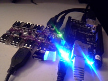 Put some masking tape or painter's tape over those 4 LED's because they are really annoyingly bright. That might sound like a joke, but if you have it blinking in the corner of your eye non-stop for hours it will actually start to give you a headache. They never stop blinking either. One of them is the Linux Kernel Heartbeat light.
They're brighter than normal LEDs too. Why? Dunno. They're blue? Blue LEDs are usually dimmer though. It's hard to even take a picture of the board while it's on! I really can't believe how rediculously annoying they are...
Alternatively, instead of putting tape over it, you could run this to actually turn them off. That's probably the right way to do this. Really, it's just the heartbeat that's annoying, but you can turn off the rest too if you want.
# just turn off the heartbeat
echo 0 > /sys/class/leds/beaglebone\:green\:usr0/brightness
# get rid of the rest too
echo 0 > /sys/class/leds/beaglebone\:green\:usr1/brightness
echo 0 > /sys/class/leds/beaglebone\:green\:usr2/brightness
echo 0 > /sys/class/leds/beaglebone\:green\:usr3/brightness
If you're worried you won't be able to tell if it crashes, just look at the LAN leds or any of the other 3 indicators. They're always blinking too.
Run a script at startup
So here is a really neat trick:
nano /home/ubuntu/bin/startup.sh
#! /bin/bash
echo 0 > /sys/class/leds/beaglebone\:green\:usr0/brightness
chmod +x /home/ubuntu/bin/startup.shsudo su
sudo crontab -e
@reboot /bin/bash /home/ubuntu/bin/startup.sh
Isn't cron cool?
Set Up Python
GPIO is done essentially by just writting and writing to the special /sys/ folder. Check out this github project for a more familiar interface for it.
Allow python to interface with i2c.
sudo apt-get install python-smbus
Benchmarks
Compare the benchmarks to those of the Raspberry Pi (wiki) using this package (zip). Also compare to my Angstrom BBB tests.
Dhrystone
Running whetstone on the Beaglebone Black with Ubuntu compiled with just -O3 yields 3,319,960 dhrystones per second. A Raspberry Pi nets 809,061.5. The BeagleBone was able to do 4.1 times more operations per second. This is also 10% faster than the same BeagleBone Black with Angstrom, the default Linux distrobution, which ran at 3,059,570. The same test ran on a desktop computer with an AMD Phenom II x4 965 gets around 25,062,657. That's more 10% of a pretty powerful desktop, which I think is somewhat impressive.
gcc dhry_1.c dhry_2.c dhry.h cpuidc.c -lm  -O3 -o dhry
./dhry
##########################################

Dhrystone Benchmark, Version 2.1 (Language: C or C++)

Optimisation    Opt 3 32 Bit
Register option not selected

       10000 runs   0.01 seconds
      100000 runs   0.10 seconds
      200000 runs   0.20 seconds
      400000 runs   0.21 seconds
      800000 runs   0.24 seconds
     1600000 runs   0.48 seconds
     3200000 runs   0.96 seconds
     6400000 runs   1.93 seconds
    12800000 runs   3.86 seconds

Final values (* implementation-dependent):

Int_Glob:      O.K.  5  Bool_Glob:     O.K.  1
Ch_1_Glob:     O.K.  A  Ch_2_Glob:     O.K.  B
Arr_1_Glob[8]: O.K.  7  Arr_2_Glob8/7: O.K.    12800010
Ptr_Glob->              Ptr_Comp:       *    94584
  Discr:       O.K.  0  Enum_Comp:     O.K.  2
  Int_Comp:    O.K.  17 Str_Comp:      O.K.  DHRYSTONE PROGRAM, SOME STRING
Next_Ptr_Glob->         Ptr_Comp:       *    94584 same as above
  Discr:       O.K.  0  Enum_Comp:     O.K.  1
  Int_Comp:    O.K.  18 Str_Comp:      O.K.  DHRYSTONE PROGRAM, SOME STRING
Int_1_Loc:     O.K.  5  Int_2_Loc:     O.K.  13
Int_3_Loc:     O.K.  7  Enum_Loc:      O.K.  1
Str_1_Loc:                             O.K.  DHRYSTONE PROGRAM, 1'ST STRING
Str_2_Loc:                             O.K.  DHRYSTONE PROGRAM, 2'ND STRING


From File /proc/cpuinfo
processor	: 0
model name	: ARMv7 Processor rev 2 (v7l)
BogoMIPS	: 198.72
Features	: swp half thumb fastmult vfp edsp thumbee neon vfpv3 tls
CPU implementer	: 0x41
CPU architecture: 7
CPU variant	: 0x3
CPU part	: 0xc08
CPU revision	: 2

Hardware	: Generic AM33XX (Flattened Device Tree)
Revision	: 0000
Serial		: 0000000000000000


From File /proc/version
Linux version 3.8.13-bone18 (root@imx6q-sabrelite-1gb) (gcc version 4.7.3 (Ubuntu/Linaro 4.7.3-1ubuntu1) ) #1 SMP Thu May 16 21:04:48 UTC 2013


Nanoseconds one Dhrystone run:       301.21
Dhrystones per Second:              3319960
VAX  MIPS rating =                  1889.56
OpenSSL
This benchmark shows numbers that are 2-10x faster than those on the Raspberry Pi . However, Angstrom is faster by about 10%. The difference? Perhaps this package has no NEON FPU optimizations on Ubuntu. I also believe the BeagleBone has a special cryptography processor which might not be taken advantage of in this test. The Dhrystone test was compiled, this OpenSSL and is probably missing some optimization argument that the Angstrom package had.
OpenSSL 1.0.1c 10 May 2012
built on: Tue Mar 19 19:30:47 UTC 2013
options:bn(64,32) rc4(ptr,char) des(idx,cisc,16,long) aes(partial) blowfish(ptr)
compiler: cc -fPIC -DOPENSSL_PIC -DZLIB -DOPENSSL_THREADS -D_REENTRANT -DDSO_DLFCN -DHAVE_DLFCN_H -DL_ENDIAN -DTERMIO -g -O2 -fstack-protector --param=ssp-buffer-size=4 -Wformat -Werror=format-security -D_FORTIFY_SOURCE=2 -Wl,-Bsymbolic-functions -Wl,-z,relro -Wa,--noexecstack -Wall -DOPENSSL_NO_TLS1_2_CLIENT -DOPENSSL_MAX_TLS1_2_CIPHER_LENGTH=50 -DOPENSSL_BN_ASM_MONT -DOPENSSL_BN_ASM_GF2m -DSHA1_ASM -DSHA256_ASM -DSHA512_ASM -DAES_ASM -DGHASH_ASM
The 'numbers' are in 1000s of bytes per second processed.
type             16 bytes     64 bytes    256 bytes   1024 bytes   8192 bytes
md2                  0.00         0.00         0.00         0.00         0.00
mdc2                 0.00         0.00         0.00         0.00         0.00
md4               7130.44k    28511.10k    79135.70k   142166.02k   185522.60k
md5               6735.29k    22954.62k    61948.74k   107186.00k   136339.07k
hmac(md5)         6964.12k    23296.17k    62451.29k   107847.13k   136203.64k
sha1              6698.12k    20571.23k    46889.18k    69689.54k    81622.11k
rmd160            5756.90k    16751.42k    36409.79k    51751.17k    58911.17k
rc4              64964.35k    72925.41k    76732.39k    77427.41k    77922.96k
des cbc          17184.97k    18237.05k    18618.82k    18752.60k    18739.89k
des ede3          6574.42k     6735.54k     6804.62k     6794.36k     6817.50k
idea cbc             0.00         0.00         0.00         0.00         0.00
seed cbc         21670.10k    22990.09k    23573.99k    23608.01k    23745.80k
rc2 cbc          12701.57k    13378.96k    13576.59k    13579.82k    13613.01k
rc5-32/12 cbc        0.00         0.00         0.00         0.00         0.00
blowfish cbc     27309.24k    29968.99k    30775.05k    31125.82k    31069.32k
cast cbc         26848.41k    29213.50k    30071.18k    30396.65k    30340.54k
aes-128 cbc      37250.31k    40851.65k    42063.71k    42548.23k    42491.55k
aes-192 cbc      31962.79k    34354.75k    35324.32k    35672.31k    35698.43k
aes-256 cbc      28581.52k    30449.05k    31271.64k    31611.70k    31551.61k
camellia-128 cbc    26676.56k    28496.71k    29167.33k    29344.13k    29277.50k
camellia-192 cbc    21532.49k    22621.60k    23114.57k    23195.84k    23143.08k
camellia-256 cbc    21538.22k    22695.82k    23031.27k    23209.75k    23145.82k
sha256            9965.51k    24221.62k    43539.86k    54826.95k    58500.20k
sha512            4207.69k    16757.43k    25271.78k    35145.54k    39798.78k
whirlpool         1579.78k     3265.95k     5289.78k     6313.06k     6654.97k
aes-128 ige      34714.63k    38142.11k    39508.96k    39855.59k    39798.33k
aes-192 ige      29820.66k    32531.41k    33528.70k    33661.52k    33790.63k
aes-256 ige      27038.57k    29091.23k    29929.06k    30019.98k    30137.21k
ghash            49881.45k    60961.91k    65236.19k    66256.57k    66803.29k
                  sign    verify    sign/s verify/s
rsa  512 bits 0.001070s 0.000107s    934.7   9379.4
rsa 1024 bits 0.006119s 0.000332s    163.4   3009.0
rsa 2048 bits 0.039563s 0.001208s     25.3    827.6
rsa 4096 bits 0.285143s 0.004634s      3.5    215.8
                  sign    verify    sign/s verify/s
dsa  512 bits 0.001092s 0.001191s    915.9    839.5
dsa 1024 bits 0.003264s 0.003762s    306.3    265.8
dsa 2048 bits 0.011669s 0.013505s     85.7     74.0
                              sign    verify    sign/s verify/s
 160 bit ecdsa (secp160r1)   0.0006s   0.0024s   1577.7    416.5
 192 bit ecdsa (nistp192)   0.0008s   0.0033s   1219.0    301.0
 224 bit ecdsa (nistp224)   0.0010s   0.0045s    959.1    224.2
 256 bit ecdsa (nistp256)   0.0013s   0.0058s    770.0    171.2
 384 bit ecdsa (nistp384)   0.0030s   0.0155s    331.5     64.4
 521 bit ecdsa (nistp521)   0.0064s   0.0351s    156.9     28.5
 163 bit ecdsa (nistk163)   0.0020s   0.0067s    495.7    149.8
 233 bit ecdsa (nistk233)   0.0042s   0.0122s    238.0     82.2
 283 bit ecdsa (nistk283)   0.0064s   0.0219s    155.9     45.6
 409 bit ecdsa (nistk409)   0.0171s   0.0488s     58.4     20.5
 571 bit ecdsa (nistk571)   0.0409s   0.1130s     24.4      8.9
 163 bit ecdsa (nistb163)   0.0020s   0.0072s    505.1    138.4
 233 bit ecdsa (nistb233)   0.0042s   0.0134s    239.8     74.5
 283 bit ecdsa (nistb283)   0.0064s   0.0247s    155.1     40.5
 409 bit ecdsa (nistb409)   0.0172s   0.0549s     58.3     18.2
 571 bit ecdsa (nistb571)   0.0410s   0.1288s     24.4      7.8
                              op      op/s
 160 bit ecdh (secp160r1)   0.0020s    501.6
 192 bit ecdh (nistp192)   0.0028s    358.5
 224 bit ecdh (nistp224)   0.0037s    272.1
 256 bit ecdh (nistp256)   0.0050s    201.4
 384 bit ecdh (nistp384)   0.0130s     77.2
 521 bit ecdh (nistp521)   0.0295s     33.9
 163 bit ecdh (nistk163)   0.0033s    301.6
 233 bit ecdh (nistk233)   0.0060s    167.9
 283 bit ecdh (nistk283)   0.0109s     91.5
 409 bit ecdh (nistk409)   0.0241s     41.4
 571 bit ecdh (nistk571)   0.0559s     17.9
 163 bit ecdh (nistb163)   0.0036s    281.4
 233 bit ecdh (nistb233)   0.0066s    152.2
 283 bit ecdh (nistb283)   0.0122s     81.9
 409 bit ecdh (nistb409)   0.0274s     36.5
 571 bit ecdh (nistb571)   0.0638s     15.7
7z
A Raspberry Pi would be expected to run 321 MIPS. Ubuntu BeagleBone gets 502 with the standard package, and 510 if you compile p7zip, showing that compiling is not really worth the effort unless it is a very important library that is proving to be a bottleneck for you.
ubuntu@arm:~$ 7z b

7-Zip 9.20  Copyright (c) 1999-2010 Igor Pavlov  2010-11-18
p7zip Version 9.20 (locale=en_US.utf8,Utf16=on,HugeFiles=on,1 CPU)

RAM size:     495 MB,  # CPU hardware threads:   1
RAM usage:    419 MB,  # Benchmark threads:      1

Dict        Compressing          |        Decompressing
      Speed Usage    R/U Rating  |    Speed Usage    R/U Rating
       KB/s     %   MIPS   MIPS  |     KB/s     %   MIPS   MIPS

22:     345    99    341    336  |     7291    99    662    658
23:     329    98    341    336  |     7176    99    661    657
24:     315    98    344    339  |     7061    99    659    655
25:     304    98    354    347  |     6929    99    655    651
----------------------------------------------------------------
Avr:           98    345    339                99    659    655
Tot:           99    502    497
Switching Back to Angstrom
To revert to the default install, the image it shipped with is available here: http://beagleboard.org/latest-images. I like the one that comes with GNOME though.
# backup
sudo dd if=/dev/sdX bs=8M | xz -c > myBeagleUbuntu.img.xz
# re-image
xz -cd Angstrom-Cloud9-IDE-GNOME-eglibc-ipk-v2012.12-beaglebone-2013.04.13.img.xz > /dev/sdX
BeagleBone Black Built-In LEDs
BeagleBone Black Built-In LEDsAbout each LED
There are four user LEDs on the BeagleBone. You can modify them, but they each have their own purposes by default. USER0 is the closest to the top in the picture at the right, and USER3 is the bottom one closest to the ethernet port.
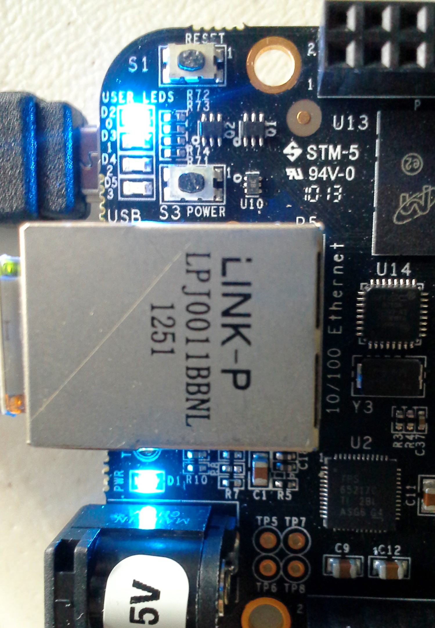
- USER0 is the heartbeat indicator from the Linux kernel.
- USER1 turns on when the SD card is being accessed
- USER2 is an activity indicator. It turns on when the kernel is not in the idle loop.
- USER3 turns on when the onboard eMMC is being accessed.
You can change each of the LED's behaviors at the following locations:
/sys/class/leds/beaglebone\:green\:usr0/
/sys/class/leds/beaglebone\:green\:usr1/
/sys/class/leds/beaglebone\:green\:usr2/
/sys/class/leds/beaglebone\:green\:usr3/
Yeah, the LEDs are blue, but the folder is called green for some reason. Also, those colons make BASH freak out a bit, so pay attention to escape them.
If you explore those directories, things start to get interesting.
First, any write operatoins will require root privileges. The use of IO redirection will require that you be the root account, not just use sudo. This is only really applicable if you are not using Angstrom, where the root account is the default account.
root@beaglebone:~# cd /sys/class/leds/beaglebone\:green\:usr0/
root@beaglebone:/sys/class/leds/beaglebone:green:usr0# ls -l
total 0
-rw-r--r-- 1 root root 4096 Jan  1 00:08 brightness
lrwxrwxrwx 1 root root    0 Jan  1 00:08 device -> ../../../gpio-leds.8
-r--r--r-- 1 root root 4096 Jan  1 00:08 max_brightness
drwxr-xr-x 2 root root    0 Jan  1 00:08 power
lrwxrwxrwx 1 root root    0 Jan  1 00:08 subsystem -> ../../../../../class/leds
-rw-r--r-- 1 root root 4096 Jan  1 00:08 trigger
-rw-r--r-- 1 root root 4096 Jan  1 00:00 uevent

root@beaglebone:/sys/class/leds/beaglebone:green:usr0# cat trigger
none nand-disk mmc0 mmc1 timer oneshot [heartbeat] backlight gpio cpu0 default-on transient
You can see that USER0 is in hearbeat trigger mode. I find that heartbeat to be annoying (it's so bright!). Let's get rid of it
Take Over a USER LED
You can change what LED blinks to indicate by changing the trigger. For example, GPIO would indicate GPIO activity.
In order to change these, you will need to become root by either using sudo bash or sudo su
Sudo alone will not help because of the I/O redirection used in these commands. You could do sudo nano trigger instead.
root@beaglebone:/sys/class/leds/beaglebone:green:usr0# echo none > trigger
root@beaglebone:/sys/class/leds/beaglebone:green:usr0# cat trigger
[none] nand-disk mmc0 mmc1 timer oneshot heartbeat backlight gpio cpu0 default-on transient
root@beaglebone:/sys/class/leds/beaglebone:green:usr0# echo 0 > brightness
Blinking a USER LED
Just a simple BASH loop:
while true; do echo 255 > brightness ; sleep 1; echo 0 > brightness; sleep 1; done;
OR you can use the timer built-in trigger
echo timer > trigger
echo 500 > delay_off
echo 50 > delay_on
You can even use it as a sort of PWM to dim the LED. There should be another way to do this, but this is all I've found.
echo timer > trigger
echo 1 > delay_on
echo 12 > delay_off
Interestingly, I think this should behave similar to the heartbeat. If the system crashes it would turn on or off completely.
BeagleBone Black Pins
BeagleBone Black PinsPinout Tables
These tables are based on the BeagleBone Black System Reference Manual (Creative Commons) by Gerald Coley of BeagleBoard.org. They aren't really available anywhere else on the internet, so I thought I'd transcribe them into a more available format.
The PROC column is the pin number on the processor.
The PIN column is the pin number on the expansion header.
The MODE columns are the mode setting for each pin. Setting each mode to align with the mode column will give that function on that pin. Each pin's mode can be set individually.
Note that the MODE5 column is absent. That is not a typo. It just doesn't do anything. The only exception is GPIO0_7 in expansion header P9 has a mmc0_sdwp
| PIN | PROC | NAME | MODE0 | MODE1 | MODE2 | MODE3 | MODE4 | MODE6 | MODE7 |
|---|---|---|---|---|---|---|---|---|---|
| 1,2 | GND | ||||||||
| 3 | R9 | GPIO1_6 | gpmc_ad6 | mmc1_dat6 | gpio1[6] | ||||
| 4 | T9 | GPIO1_7 | gpmc_ad7 | mmc1_dat7 | gpio1[7] | ||||
| 5 | R8 | GPIO1_2 | gpmc_ad2 | mmc1_dat2 | gpio1[2] | ||||
| 6 | T8 | GPIO1_3 | gpmc_ad3 | mmc1_dat3 | gpio1[3] | ||||
| 7 | R7 | TIMER4 | gpmc_advn_ale | timer4 | gpio2[2] | ||||
| 8 | T7 | TIMER7 | gpmc_oen_ren | timer7 | gpio2[3] | ||||
| 9 | T6 | TIMER5 | gpmc_be0n_cle | timer5 | gpio2[5] | ||||
| 10 | U6 | TIMER6 | gpmc_wen | timer6 | gpio2[4] | ||||
| 11* | R12 | GPIO1_13 | gpmc_ad13 | lcd_data18 | mmc1_dat5* | mmc2_dat1 | eQEP2B_in | gpio1[13] | |
| 12* | T12 | GPIO1_12 | gpmc_ad12 | lcd_data19 | mmc1_dat4* | mmc2_dat0 | EQEP2A_IN | gpio1[12] | |
| 13* | T10 | EHRPWM2B | gpmc_ad9 | lcd_data22 | mmc1_dat1* | mmc2_dat5 | ehrpwm2B | gpio0[23] | |
| 14* | T11 | GPIO0_26 | gpmc_ad10 | lcd_data21 | mmc1_dat2* | mmc2_dat6 | ehrpwm2_tripzone | gpio0[26] | |
| 15* | U13 | GPIO1_15 | gpmc_ad15 | lcd_data16 | mmc1_dat7* | mmc2_dat3 | eQEP2_strobe | gpio1[15] | |
| 16* | V13 | GPIO1_14 | gpmc_ad14 | lcd_data17 | mmc1_dat6* | mmc2_dat2 | eQEP2_index | gpio1[14] | |
| 17* | U12 | GPIO0_27 | gpmc_ad11 | lcd_data20 | mmc1_dat3* | mmc2_dat7 | ehrpwm0_synco | gpio0[27] | |
| 18 | V12 | GPIO2_1 | gpmc_clk_mux0 | lcd_memory_clk | gpmc_wait1 | mmc2_clk | mcasp0_fsr | gpio2[1] | |
| 19* | U10 | EHRPWM2A | gpmc_ad8 | lcd_data23 | mmc1_dat0* | mmc2_dat4 | ehrpwm2A | gpio0[22] | |
| 20* | V9 | GPIO1_31 | gpmc_csn2 | gpmc_be1n | mmc1_cmd* | gpio1[31] | |||
| 21* | U9 | GPIO1_30 | gpmc_csn1 | gpmc_clk | mmc1_clk* | gpio1[30] | |||
| 22 | V8 | GPIO1_5 | gpmc_ad5 | mmc1_dat5 | gpio1[5] | ||||
| 23 | U8 | GPIO1_4 | gpmc_ad4 | mmc1_dat4 | gpio1[4] | ||||
| 24 | V7 | GPIO1_1 | gpmc_ad1 | mmc1_dat1 | gpio1[1] | ||||
| 25 | U7 | GPIO1_0 | gpmc_ad0 | mmc1_dat0 | gpio1[0] | ||||
| 26 | V6 | GPIO1_29 | gpmc_csn0 | gpio1[29] | |||||
| 27* | U5 | GPIO2_22 | lcd_vsync* | gpmc_a8 | gpio2[22] | ||||
| 28* | V5 | GPIO2_24 | lcd_pclk* | gpmc_a10 | gpio2[24] | ||||
| 29* | R5 | GPIO2_23 | lcd_hsync* | gpmc_a9 | gpio2[23] | ||||
| 30* | R6 | GPIO2_25 | lcd_ac_bias_en* | gpmc_a11 | gpio2[25] | ||||
| 31* | V4 | UART5_CTSN | lcd_data14* | gpmc_a18 | eQEP1_index | mcasp0_axr1 | uart5_rxd | uart5_ctsn | gpio0[10] |
| 32* | T5 | UART5_RTSN | lcd_data15* | gpmc_a19 | eQEP1_strobe | mcasp0_ahclkx | mcasp0_axr3 | uart5_rtsn | gpio0[11] |
| 33* | V3 | UART4_RTSN | lcd_data13* | gpmc_a17 | eQEP1B_in | mcasp0_fsr | mcasp0_axr3 | uart4_rtsn | gpio0[9] |
| 34* | U4 | UART3_RTSN | lcd_data11* | gpmc_a15 | ehrpwm1B | mcasp0_ahclkr | mcasp0_axr2 | uart3_rtsn | gpio2[17] |
| 35* | V2 | UART4_CTSN | lcd_data12* | gpmc_a16 | eQEP1A_in | mcasp0_aclkr | mcasp0_axr2 | uart4_ctsn | gpio0[8] |
| 36* | U3 | UART3_CTSN | lcd_data10* | gpmc_a14 | ehrpwm1A | mcasp0_axr0 | uart3_ctsn | gpio2[16] | |
| 37* | U1 | UART5_TXD | lcd_data8* | gpmc_a12 | ehrpwm1_tripzone | mcasp0_aclkx | uart5_txd | uart2_ctsn | gpio2[14] |
| 38* | U2 | UART5_RXD | lcd_data9* | gpmc_a13 | ehrpwm0_synco | mcasp0_fsx | uart5_rxd | uart2_rtsn | gpio2[15] |
| 39* | T3 | GPIO2_12 | lcd_data6* | gpmc_a6 | eQEP2_index | gpio2[12] | |||
| 40* | T4 | GPIO2_13 | lcd_data7* | gpmc_a7 | eQEP2_strobe | pr1_edio_data_out7 | gpio2[13] | ||
| 41* | T1 | GPIO2_10 | lcd_data4* | gpmc_a4 | eQEP2A_in | gpio2[10] | |||
| 42* | T2 | GPIO2_11 | lcd_data5* | gpmc_a5 | eQEP2B_in | gpio2[11] | |||
| 43* | R3 | GPIO2_8 | lcd_data2* | gpmc_a2 | ehrpwm2_tripzone | gpio2[8] | |||
| 44* | R4 | GPIO2_9 | lcd_data3* | gpmc_a3 | ehrpwm0_synco | gpio2[9] | |||
| 45* | R1 | GPIO2_6 | lcd_data0* | gpmc_a0 | ehrpwm2A | gpio2[6] | |||
| 46* | R2 | GPIO2_7 | lcd_data1* | gpmc_a1 | ehrpwm2B | gpio2[7] | |||
* some pins are used by the internal storage (eMMC), and HDMI. 11-21 are used by eMMC. 27-46 are used by HDMI.
| PIN | PROC | NAME | MODE0 | MODE2 | MODE3 | MODE4 | MODE6 | MODE7 |
|---|---|---|---|---|---|---|---|---|
| 1,2 | GND | |||||||
| 3,4 | DC_3.3V | |||||||
| 5,6 | VDD_5V | |||||||
| 7,8 | SYS_5V | |||||||
| 9 | PWR_BUT | |||||||
| 10 | A10 | RESET_OUT | ||||||
| 11 | T17 | gpmc_wait0 | mii2_crs | gpmc_csn4 | rmii2_crs_dv | mmc1_sdcd | uart4_rxd_mux2 | gpio0[30] |
| 12 | U18 | gpmc_be1n | mii2_col | gpmc_csn6 | mmc2_dat3 | gpmc_dir | mcasp0_aclkr_mux3 | gpio1[28] |
| 13 | U17 | gpmc_wpn | mii2_rxerr | gpmc_csn5 | rmii2_rxerr | mmc2_sdcd | uart4_txd_mux2 | gpio0[31] |
| 14 | U14 | gpmc_a2 | mii2_txd3 | rgmii2_td3 | mmc2_dat1 | gpmc_a18 | ehrpwm1A_mux1 | gpio1[18] |
| 15 | R13 | gpmc_a0 | gmii2_txen | rmii2_tctl | mii2_txen | gpmc_a16 | ehrpwm1_tripzone | gpio1[16] |
| 16 | T14 | gpmc_a3 | mii2_txd2 | rgmii2_td2 | mmc2_dat2 | gpmc_a19 | ehrpwm1B_mux1 | gpio1[19] |
| 17 | A16 | spi0_cs0 | mmc2_sdwp | I2C1_SCL | ehrpwm0_synci | gpio0[5] | ||
| 18 | B16 | spi0_d1 | mmc1_sdwp | I2C1_SDA | ehrpwm0_tripzone | gpio0[4] | ||
| 19 | D17 | uart1_rtsn | timer5 | dcan0_rx | I2C2_SCL | spi1_cs1 | gpio0[13] | |
| 20 | D18 | uart1_ctsn | timer6 | dcan0_tx | I2C2_SDA | spi1_cs0 | gpio0[12] | |
| 21 | B17 | spi0_d0 | uart2_txd | I2C2_SCL | ehrpwm0B | EMU3_mux1 | gpio0[3] | |
| 22 | A17 | spi0_sclk | uart2_rxd | I2C2_SDA | ehrpwm0A | EMU2_mux1 | gpio0[2] | |
| 23 | V14 | gpmc_a1 | gmii2_rxdv | rgmii2_rxdv | mmc2_dat0 | gpmc_a17 | ehrpwm0_synco | gpio1[17] |
| 24 | D15 | uart1_txd | mmc2_sdwp | dcan1_rx | I2C1_SCL | gpio0[15] | ||
| 25 | A14 | mcasp0_ahclkx | eQEP0_strobe | mcasp0_axr3 | mcasp1_axr1 | EMU4_mux2 | gpio3[21] | |
| 26 | D16 | uart1_rxd | mmc1_sdwp | dcan1_tx | I2C1_SDA | gpio0[14] | ||
| 27 | C13 | mcasp0_fsr | eQEP0B_in | mcasp0_axr3 | mcasp1_fsx | EMU2_mux2 | gpio3[19] | |
| 28 | C12 | mcasp0_ahclkr | ehrpwm0_synci | mcasp0_axr2 | spi1_cs0 | eCAP2_in_PWM2_out | gpio3[17] | |
| 29 | B13 | mcasp0_fsx | ehrpwm0B | spi1_d0 | mmc1_sdcd_mux1 | gpio3[15] | ||
| 30 | D12 | mcasp0_axr0 | ehrpwm0_tripzone | spi1_d1 | mmc2_sdcd_mux1 | gpio3[16] | ||
| 31 | A13 | mcasp0_aclkx | ehrpwm0A | spi1_sclk | mmc0_sdcd_mux1 | gpio3[14] | ||
| 32 | VADC | |||||||
| 33 | C8 | AIN4 | ||||||
| 34 | AGND | |||||||
| 35 | A8 | AIN6 | ||||||
| 36 | B8 | AIN5 | ||||||
| 37 | B7 | AIN2 | ||||||
| 38 | A7 | AIN3 | ||||||
| 39 | B6 | AIN0 | ||||||
| 40 | C7 | AIN1 | ||||||
| 41# | D14 | xdma_event_intr1 | tclkin | clkout2 | timer7_mux1 | EMU3_mux0 | gpio0[20] | |
| D13 | mcasp0_axr1 | eQEP0_index | Mcasp1_axr0 | emu3 | gpio3[20] | |||
| 42@ | C18 | eCAP0_in_PWM0_out | uart3_txd | spi1_cs1 | pr1_ecap0_ecap _capin_apwm_o |
spi1_sclk | xdma_event_intr2 | gpio0[7] |
| B12 | Mcasp0_aclkr | eQEP0A_in | Mcaspo_axr2 | Mcasp1_aclkx | gpio3[18] | |||
Selecting Modes
Using the "everything is a file" sys directory, you can use BASH or whatever to change the mode number for the pin in the NAME column.
echo 7 > /sys/kernel/debug/omap_mux/gpmc_ad4
echo 36 > /sys/class/gpio/export
echo out > /sys/class/gpio/gpio32/direction
echo 1 > /sys/class/gpio/gpio32/value
If you are using windows, TI has this GUI you can use called PinMuxTool / Pin Mux Utility. The BBB is AM335x r2 based.
The above only works if you're using the older kernel. The new 3.8 based kernel is missing this nifty pin mux feature. However, you can still check what they're muxed at even if you can't change them easily at runtime by looking at
/sys/kernel/debug/pinctrl/44e10800.pinmux/pingroups
root@arm:/sys/kernel/debug/pinctrl/44e10800.pinmux# cat pingroups
registered pin groups:
group: pinmux_userled_pins
pin 21 (44e10854)
pin 22 (44e10858)
pin 23 (44e1085c)
pin 24 (44e10860)

group: pinmux_rstctl_pins
pin 20 (44e10850)

group: pinmux_i2c0_pins
pin 98 (44e10988)
pin 99 (44e1098c)

group: pinmux_i2c2_pins
pin 94 (44e10978)
pin 95 (44e1097c)

group: pinmux_emmc2_pins
pin 32 (44e10880)
pin 33 (44e10884)
pin 0 (44e10800)
pin 1 (44e10804)
pin 2 (44e10808)
pin 3 (44e1080c)
pin 4 (44e10810)
pin 5 (44e10814)
pin 6 (44e10818)
pin 7 (44e1081c)

group: pinmux_userled_pins
pin 21 (44e10854)
pin 22 (44e10858)
pin 23 (44e1085c)
pin 24 (44e10860)

group: mcasp0_pins
pin 107 (44e109ac)
pin 103 (44e1099c)
pin 101 (44e10994)
pin 100 (44e10990)
pin 106 (44e109a8)

group: nxp_hdmi_bonelt_pins
pin 108 (44e109b0)
pin 40 (44e108a0)
pin 41 (44e108a4)
pin 42 (44e108a8)
pin 43 (44e108ac)
pin 44 (44e108b0)
pin 45 (44e108b4)
pin 46 (44e108b8)
pin 47 (44e108bc)
pin 48 (44e108c0)
pin 49 (44e108c4)
pin 50 (44e108c8)
pin 51 (44e108cc)
pin 52 (44e108d0)
pin 53 (44e108d4)
pin 54 (44e108d8)
pin 55 (44e108dc)
pin 56 (44e108e0)
pin 57 (44e108e4)
pin 58 (44e108e8)
pin 59 (44e108ec)

group: nxp_hdmi_bonelt_off_pins
pin 108 (44e109b0)
Check Pin Statuses
root@beaglebone:~# cat /sys/kernel/debug/gpio
GPIOs 0-31, gpio:

GPIOs 32-63, gpio:
 gpio-52  (eMMC_RSTn           ) out lo
 gpio-53  (beaglebone:green:usr) out lo
 gpio-54  (beaglebone:green:usr) out lo
 gpio-55  (beaglebone:green:usr) out hi
 gpio-56  (beaglebone:green:usr) out lo
 gpio-59  (McASP Clock Enable P) out hi

GPIOs 64-95, gpio:

GPIOs 96-127, gpio:
Power Limitations
Be careful about this one, there are some much lower limits than you might be used to
| Pin Type | Maximum Voltage | Maximum Current |
| AIN | 1.8V | |
| GPIO | 3.3V | 4mA - 6mA |
| VDD 3.3 | 3.3V | 250mA |
| VDD 5V | 5V* | 1000mA * |
| SYS 5V | 5V | 250mA |
| VDD ADC | 1.8V | 0? |
| SYS 5V | 5V | 250mA |
* VDD only works when the 5V barrel jack is used
i2c
It is recommended that you use I2C2 on pins 19 and 20 with the /dev/i2c-3 device.
| Mode Name | Port | Physical Pin Number | Block Device |
| I2C1 | P9 | 17 & 18 or 24 & 26 | ? |
| I2C2 | P9 | 19 & 20 or 21 & 22 | /dev/i2c-3 |
To check which i2c interfaces are avaible, check
root@arm:~# ls -l /dev/i2c*
crw-rw---- 1 root i2c 89, 0 Jun  5 04:34 /dev/i2c-0
crw-rw---- 1 root i2c 89, 1 Jun  5 04:34 /dev/i2c-1
To see what addresses are being used, try the i2cdetect command. In the below example, I have a temperature sensor hooked up to pins 19 and 20 that is using 48. Also note that the UU addresses are being used by the system and are unavailable.
root@beaglebone:~# i2cdetect -y -r 3
     0  1  2  3  4  5  6  7  8  9  a  b  c  d  e  f
00:          -- -- -- -- -- -- -- -- -- -- -- -- --
10: -- -- -- -- -- -- -- -- -- -- -- UU -- -- -- --
20: -- -- -- -- -- -- -- -- -- -- -- -- -- -- -- --
30: -- -- -- -- -- -- -- -- -- -- -- -- -- -- -- --
40: -- -- -- -- -- -- -- -- 48 -- -- -- -- -- -- --
50: -- -- -- -- UU UU UU UU -- -- -- -- -- -- -- --
60: -- -- -- -- -- -- -- -- -- -- -- -- -- -- -- --
70: -- -- -- -- -- -- -- --BeagleBone Internet over USB only
BeagleBone Internet over USB onlySure, the BeagleBone and BeagleBone Black come with an ethernet port on them, but why have to get another cable out? You might not even be anywhere near the router. The BeagleBone images automatically do network communcations over USB, as shown by how you can go to 192.168.7.2 from your browser to see the BeagleBone start page and http://192.168.7.2:3000/ to use the Cloud9 editor hosted on the BeagleBone. The problem is that the host computers do not usually relay network traffic to new interfaces. I don't know why not. It would be nice if you could just connect stuff to any connection and it'd always work, but it's not hard to set up NAT and such once you know how to do it. The connection over USB might be slighlty slower than the dedicated connection, since USB is slower and is sharing the connection with things JTAG communication and mass storage. For all I know, though, the ethernet on the BeagleBone is actually controlled by the same USB controller, so it might not be at all different!
On the BeagleBone
ifconfig usb0 192.168.7.2
route add default gw 192.168.7.1
On Linux computer:
sudo su
#eth0 is my internet facing interface, eth3 is the BeagleBone USB connection
ifconfig eth3 192.168.7.1
iptables --table nat --append POSTROUTING --out-interface eth0 -j MASQUERADE
iptables --append FORWARD --in-interface eth3 -j ACCEPT
echo 1 > /proc/sys/net/ipv4/ip_forward
On a Windows computer, I would think you could use the graphical Internet Connection Sharing feature.
BeagleBone Security System
BeagleBone Security SystemSince the BeagleBone (and the Raspberry Pi) is Linux based, and has usb ports, it is actually very easy (and cheap) to make a security camera system. All you need are USB webcams. Just about any will do. I got four for $16 on Amazon. More expensive ones might say they have higher resolution, but what they are actually reporting is the still photo quality, not streaming video quality. Unless you get a USB 3.0 webcam, which would not be supported by either hobbyist computer, it is impossible to stream HD (1080) video, but some might be able to 720. Even if it were possible, it becomes difficult to store so many photos or videos of that size. So keep it cheap, but make sure it is Linux compatible (UVC/V4L), which can be difficult to find sometimes.
One major limitation of this kind of system is the cord length limit on USB, which is only 2-7 meters (6-17 feet). It should be possible to get around this limitation with the use of hubs and repeaters.
Motion Detection Software
Motion is a great system for security systems. It monitors the camera for any motion and saves pictures or video (or both) only when there is something happening, which is great for saving space.
Installation (BeagleBone)
Motion is actually in the Angstrom package repositories! Why does that surprise me so much? Oh wait. They're for the wrong architecture ARM7a vs ARM7l. Would it work anyway? No idea. Probably best not to try. Ok, so this isn't going to be as easy as it could be. Download the source from the motion homepage by finding a link to it in your web browser and then:
opkg install kernel-module-uvcvideo libavformat-staticdev
ln -s /usr/include/libv4l1-videodev.h /usr/include/linux/videodev.h
ln -s /usr/include/libavformat/avformat.h /usr/include/avformat.h
ln -s /usr/include/libavformat/avio.h /usr/include/avio.h
ln -s /usr/include/libavutil/avstring.h /usr/include/avstring.h
ln -s /usr/include/libavutil/attributes.h /usr/include/attributes.h

wget $URLGOESHERE
tar -xzf motion.tar.gz
#it will probably tell you the time is in the future.
#BeagleBone does not have the correct time. It has no clock.
cd motion-3.2.12/
./configure
make
make install
After all of that, I never got it to compile. I think it might be because the version of ffmpeg currently in the repo is old, but I'm not sure since this seems to have more to do with uvc.
track.c: In function 'uvc_center':
track.c:587:29: error: storage size of 'control_s' isn't known
track.c:589:24: error: 'V4L2_CID_PRIVATE_BASE' undeclared
If you use an older version of motion (3.2.6), you can get a different error involving jpeglib, but it's no easier to figure out.
This is a very good example of why Ubuntu on the BeagleBone is desirable. The installation process on Ubuntu is as easy as it is for the Raspbian (both are Debian based). So, even though I couldn't get it working in Angstrom, it is still possible to use a BeagleBone for this project
Raspberry Pi Installation
Motion is also in the Raspbian package repositories, which is not surprising since it's basically Debian.
sudo apt-get install motion
Isn't that easy? Why yes. Yes it is.
Configuration
Motion has a very usable configuration file in /etc/motion/motion.conf. Here are some useful configuration options:
width 640
height 480
framerate 10

# Threshold for number of changed pixels in an image that
threshold 1500

# The quality (in percent) to be used by the jpeg compression (default: 75)
quality 50

# Use ffmpeg to encode mpeg movies in realtime (default: off)
ffmpeg_cap_new on

# Target base directory for pictures and films
target_dir /var/log/security

#break into different folders based on days, not subdivided into hours
jpeg_filename %Y%m%d/camera-%t/motions/%H%M%S-%v%q
movie_filename %Y%m%d/camera-%t/movie/%v-%Y%m%d%H%M%S

# The mini-http server listens to this port for requests (default: 0 = disabled)
webcam_port 8081
# Maximum framerate for webcam streams (default: 1)
webcam_maxrate 10
# Restrict webcam connections to localhost only (default: on)
webcam_localhost off
Saving movies instead of just images turns out to be surprisingly efficient. For example, a day in my setup yielded 7640 images and only 35 movies, which meant 210MB vs 55MB of storage space. So, to save space, "output_motion off" might be a good change. Saving both kinds of motions (video and stills) at 640x480, 2.3GB could be used on a busy day, but with an average of more like 100MB. Obviously, it will depend on how often things move in your cameras' field of view and what you have your threshold set at. In most cases, you will want a large SD card or maybe even an external USB HDD to store these on.
One really cool feature of motion is that it can stream the webcam image over HTTP as an mjpeg. So, by visiting the BeagleBone's address and webcam_port (ex http://beaglebone.local/8081), you can watch the in a browser from somewhere in your own network. However, if you do port forwarding, or the beaglebone has a public IP, you can keep an eye on things from anywhere in the world. It does not, however, have a way to password protect the stream. So keep that in mind before making it public.
Automatic Cleanup
To make sure that the local storage does not fill up, you can delete old data. This can be done automatically based on age using cron and the find program. The following crontab will search for anything over the specified age (in days) and delete it. Note that this does not guarantee that there will be enough disk space. For example, if a few days with lots of motion occur, it could fill up before influx ages enough.
crontab -e
# m h dom mon dow   command
45  1  *   *   * find /var/log/security/ -maxdepth 1 -ctime +145 -exec rm -rf {} \;
# delete anything (non-recursively) in /var/log/security older than 145 days
Electronics
ElectronicsMany projects do not actually require much knowledge about electricity. Despite what is learned in places like physics classes, it is almost never necessary to use Ohm's law to calculate voltage, resistance, and current in a circuit. Many of the components that you will use are really self-contained and just need to be hooked up properly. Really, it often boils down to reading specification sheets and documentation. The devices will say what voltage they need and how much current they will draw and all you have to do is make sure it is getting what it needs.
IO Port Expander (MCP23017 and MCP23008)
IO Port Expander (MCP23017 and MCP23008)The MCP23017 and MCP23008 integrated circuits are a great way to add more I/O pins to a microcontroller. They use the i2c standard, so they can share the same serial line with 254 other sensors and even up to 8 other chips of the same exact type. They are particularly good for a Raspberry Pi because they have higher current capabilities than the Raspberry Pi's GPIO pins. The MCP can supply 25mA per pin and the Raspberry Pi can only do less than 16mA per pin. 20mA is enough to fully power a strong LED, so 16mA may not be enough in some cases. More importantly, through the use of a relatively cheap logic level shifter, many 5V I/O pins can be added to a single serial channel despite the fact that the Raspbery Pi uses 3.3V GPIO and serial.
| GPB0 | ↔ | • 1 | ◡ | 28 | ↔ | GPA7 |
| GPB1 | ↔ | 2 | 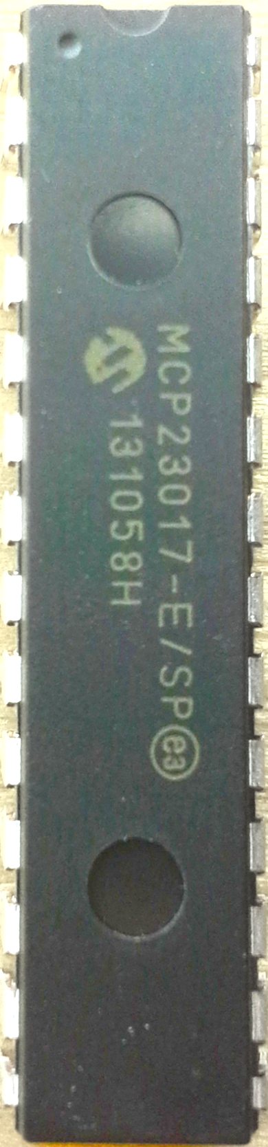 |
27 | ↔ | GPA6 |
| GPB2 | ↔ | 3 | 26 | ↔ | GPA5 | |
| GPB3 | ↔ | 4 | 25 | ↔ | GPA4 | |
| GPB4 | ↔ | 5 | 24 | ↔ | GPA3 | |
| GPB5 | ↔ | 6 | 23 | ↔ | GPA2 | |
| GPB6 | ↔ | 7 | 22 | ↔ | GPA1 | |
| GPB7 | ↔ | 8 | 21 | ↔ | GPA0 | |
| VIN | → | 9 | 20 | → | INTA | |
| GND | → | 10 | 19 | → | INTB | |
| 11 | 18 | ← | RESET | |||
| SCL | → | 12 | 17 | ← | ADDR2 | |
| SDA | ↔ | 13 | 16 | ← | ADDR1 | |
| 14 | 15 | ← | ADDR0 |
| SCL | ↔ | • 1 | ◡ | 18 | ← | VIN |
| SDA | ↔ | 2 | 17 | ↔ | GP7 | |
| ADDR2 | → | 3 | 16 | ↔ | GP6 | |
| ADDR1 | → | 4 | 15 | ↔ | GP5 | |
| ADDR0 | → | 5 | 14 | ↔ | GP4 | |
| RESET | → | 6 | 13 | ↔ | GP3 | |
| 7 | 12 | ↔ | GP2 | |||
| INT | ← | 8 | 11 | ↔ | GP1 | |
| GND | → | 9 | 10 | ↔ | GP0 |
*The bold pins are required. In particular, it is important to set the RESET pin to high.
GPA#, GPB#, GP# are the GPIO pins. On the 16 pin version, there are two ports denoted by the A and B (PORTA, PORTB).
INTA, INTB, INT are the interrupt outputs that can be monitored by the microcontroller to notify it when inputs change. On the 16 pin variant, there is one for each GPIO port.
| 0 | 1 | 0 | 0 | ADDR2 | ADDR1 | ADDR0 | Hex Addr. | Dec. Addr. |
| 0 | 1 | 0 | 0 | 0 | 0 | 0 | 0x20 | 32 |
| 0 | 1 | 0 | 0 | 0 | 0 | 1 | 0x21 | 33 |
| 0 | 1 | 0 | 0 | 0 | 1 | 0 | 0x22 | 34 |
| 0 | 1 | 0 | 0 | 0 | 1 | 1 | 0x23 | 35 |
| 0 | 1 | 0 | 0 | 1 | 0 | 0 | 0x24 | 36 |
| 0 | 1 | 0 | 0 | 1 | 0 | 1 | 0x25 | 37 |
| 0 | 1 | 0 | 0 | 1 | 1 | 0 | 0x26 | 38 |
| 0 | 1 | 0 | 0 | 1 | 1 | 1 | 0x27 | 39 |
The ADDR# pins can be set to high or low to change the address by 1 or 0 in the style in the address table allowing for a possible total of 8 different addresses, and therefore allowing up to 8 chips total. Both the 16 GPIO and 8 GPIO pin variants start at 0x20, so mixing the type will not help get more. If you are using more than 128 pins, you might want to consider alternatives like shift registers.
The RESET pin can be used to clear the registers and set it back to its power-on state, but really that isn't very useful since you can always use serail commands. So, usually you will just wire it directly to HIGH (3.3v or 5v) so that it always stay on.
Arduino
There is an Arduino library made available by adafruit on GitHub. Usage is very simple:
#include <Wire.h>
#include "Adafruit_MCP23017.h"

Adafruit_MCP23017 mcp;

# define BLINKPIN 0
# define INPUTPIN 1
# define ECHOPIN 13

// blinks MCP pin 0 on and off
// turns MCP pin 13 on when MCP pin 1 is high or unplugged

void setup() {
  mcp.begin();      // use default address 0x20 (0,0,0)

  mcp.pinMode(BLINKPIN, OUTPUT);

  mcp.pinMode(INPUTPIN, INPUT);
  mcp.pullUp(INPUTPIN, HIGH);  // turn on a 100K pullup internally
}

void loop() {
  delay(100);
  mcp.digitalWrite(BLINKPIN, HIGH);
  delay(100);
  mcp.digitalWrite(BLINKPIN, LOW);

  // ECHO only updates every 200 ms
  digitalWrite(ECHOPIN, mcp.digitalRead(INPUTPIN));
}
The major problem with the above code is that the ECHO is not updated until the delays are done. To get by that limitation, something like Metro or Kernel could be used, or simply checking the time yourself. This example was built just to show the bare minimum of how to interface with the MCP, not to show a practical application though.
Raspberry Pi
Adafruit also provies a Python library for the Raspberry Pi, which is also easy to use.
from Adafruit_MCP230XX import *

# Use busnum = 0 for older Raspberry Pi's (256MB)
# Use busnum = 1 for new Raspberry Pi's (512MB with mounting holes)
mcp = Adafruit_MCP230XX(busnum = 1, address = 0x20, num_gpios = 16)

# Set pins 0, 1 and 2 to output (you can set pins 0..15 this way)
mcp.config(0, mcp.OUTPUT)
mcp.config(1, mcp.OUTPUT)
mcp.config(2, mcp.OUTPUT)

# Set pin 3 to input with the pullup resistor enabled
mcp.pullup(3, 1)
# Read pin 3 and display the results
#bitshift output, third bit is the output
print "%d: %x" % (3, mcp.input(3) >> 3)

# Python speed test on output 0 toggling at max speed
while (True):
  mcp.output(0, 1)  # Pin 0 High
  mcp.output(0, 0)  # Pin 1 Low
NPN and PNP Transistors
NPN and PNP TransistorsIntroduction
Transistors are incredibly useful devices. My favorite use for bipolar junction transistors (BJTs) is switches. By either applying a high (1) or low (0) voltage to them, the transistors switch from on to off or vice versa. These transistors also can be used for current amplification. They can also be used along side diodes to create logic gates. However, this will focus on the difference between the NPN and PNP transistors.
How to choose between the NPN and PNP transistors
The two transistors can be used to perform the same thing, such as switching, but how to use them differs. Below I explain how both the NPN and PNP function and then depending on your application, you can choose whichever transistor is more applicable.
NPN Transistor
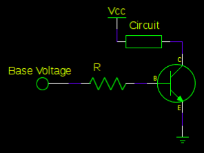
NPN transistors flow current from the collector to the emitter. Generally, the emitter is grounded and the circuit that will be powered on and off is put on the powered collector side of the transistor. It should be noted that although the top part of the circuit may be connected to a voltage, no current actual runs through the circuit until it is connected to ground, which is separated from the circuit by the NPN transistor. The NPN transistor is on when there is a high voltage (1) connected to the base and off when there is a low voltage (0 - generally ground) connected to the base. It is also important to know that the voltage on the base pin is connected to how the transistor is connected in the circuit. The base pin voltage in this configuration is ground, which is likely due to the grounded emitter pin. This is why when the NPN transistor's base pin is then connected to a high voltage, such as 5V, current flows into the transistor and connects the emitter and collector.
PNP Transistor
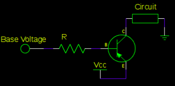
PNP transistors flow current from the emitter to the collector. Generally, the emitter is powered and the circuit that will be powered on and off is put on the collector side of the transistor connected to ground. It should be noted that the circuit will once again not be powered unless the transistor is in the on position. The PNP transistor is on when there is a low voltage (0 - generally ground) connected to the base and off when there is a high voltage (1) connected to the base. In the case of the PNP transistor, the voltage on the base pin is approximately what the Vcc voltage is. When I tested this with a 5V Vcc, the base pin voltage was approximately 4.6V. This is why when the PNP base pin is connected to ground, current will flow to the transistor, which connects the emitter to the collector.
Cautions
When working with transistors as with all components in circuits, care has to be taken to analyze how the current flows through the circuit. With transistors, it is a little trickier since there are three pins rather than two like with resistors and capacitors. However, as stated previously, they are very useful components. If something is not working the way you expect, I have found that there is generally current flowing into or from a base pin unintentionally.
For a more thorough discussion visit here.
Sensors
SensorsPreface
Here is a list of sensors that we have found useful for various projects. Each tutorial for a sensor gives an explanation of what it is, potential uses, and sample code.
GP2Y0D810 Infrared Sensor
GP2Y0D810 Infrared SensorIntroduction
Infrared sensors are a form of distance sensors. They tend to be more susceptible to inaccuracies. This is because they send out infrared light and wait for the light to tell distance. Certain colors, especially black, absorb some of the infrared light and may return a false reading.
This was tested on a variety of objects that were what would be considered black. A reading was obtained from almost all of the tested objects, although the distance returned varied. There was one black object that the sensor could not detect at all. The moral of this story is do not rely solely on infrared sensors for distance detection. Redundancy is key when working on robots.
For the GP2Y0D810 sensor, Pololu makes a breakout board that has three pins on it: VIN, GND, and OUT.
Schematic
The important thing to note is that the OUT pin goes to an analog pin.
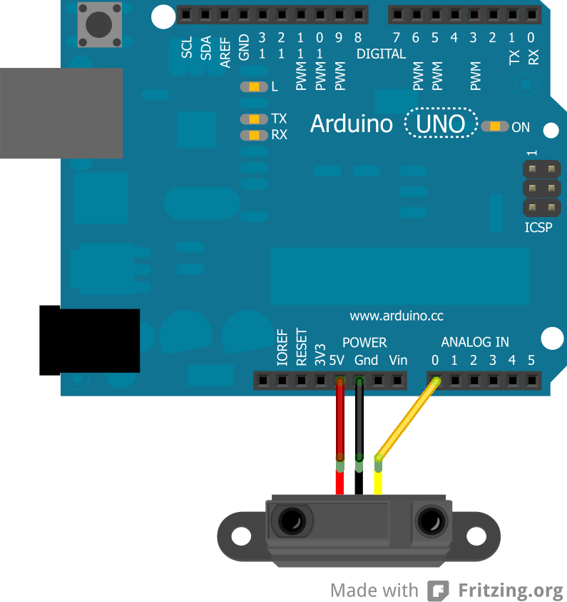
Coding
This sensor was used on a robot that did not want to get too close to objects, so when the analog value hit a given number that meant that the robot was within 10cm of an object on the side that the sensor faced. Knowing the value, the robot would be able to respond accordingly.
Below is the code explaining how the sensor works. The value that is given was found by holding objects over the sensor and lowering them until the built-in LED would light up. The value was found to be consistent.
int irPin = A0;
int sensorValue = 0;

void setup() {
  Serial.begin(9600);
}

void loop() {
  sensorValue = analogRead(irPin);

  //check for value of 85 or less for distance testing
  if (sensorValue <= 85) {
    Serial.println("Too close");
  }

  delay(1000);
}
This is just a very simple use of the infrared sensor, but an effective one depending on the purpose.
GP2Y0A02YK Infrared Sensor in Real Distance
GP2Y0A02YK Infrared Sensor in Real DistanceIntroduction
 This is a longer range version of the GP2Y0D810 Infrared Sensor. They're about 15$, and work fairly well for distances between 0.5 meters and 1.5 meters. It is important to note that the distance to voltage curve is not linear. So, if you want the real distance, measured in mm, you'll need to come up with a best fit curve based on some experimental data.
Like the midrange version, the wiring is easy. Red goes to +5V, Black goes to GND, and white goes to an analog pin (in my case A0). You can even hook multples of them up as long as you use a seperate white to analog pin.
Again, IR does not the same on all surfaces. It depends on their reflectivity. For example, black surfaces tend to appear to be really far away since they don't bounce back much light. So, when you gather your data to make a best fit curve, you should use a surface similar to the one you plan on detecting.
Collect Some Data
I used 5V input voltage hooked up to an Arduino's analog read pin. I laid down a measuring tape and recorded the output from analogRead() at each distance. Here are the results:
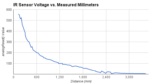
Fit the Data
I think a polynomial regression would best fit the curve. I used a cubic polynomial. Here are the coefficients that I found based on my samples:
-0.00003983993846 v3+ 0.0456899769 v2 - 17.48535575 v + 2571.052715
Convert to Code
Once you have a good fit curve, the code is fairly straightforward:
//some globals used for averaging the samples

int numSamples = 0;
long irSum = 0;

//convert voltage to millimeters
int convertIRvoltsToMM(float v) {
    return -0.00003983993846*v*v*v+ 0.0456899769 *v*v - 17.48535575 * v + 2571.052715;
}


void setup() {}

void loop() {
    irSum += analogRead(A0);
    numSamples++;


    if ( numSamples >= 10 ) {
        int distance = convertIRvoltsToMM( float(irSum) / float(numSamples) );

        Serial.println( distance );
        irSum = numSamples = 0;
    }
}
Conclusion
It may be a good idea to take samples at a somewhat rapid frequency and average them together to produce more accurate results. Even after doing this, mine still fluctuates by a couple of centimeters even in its acurrate range. There is a chance this could be cleaned up with a better electronic circuit though.
You can also hook up two of these, take samples from both of them, and average the two. They do not seem to interfere with each other too much.
The variability of detection with reflection surface colors is also a pretty significant drawback. It is enough of a drawback that if you are really looking to measure anything in real distance, you probably should not use them. They probably work better as "threshold" detectors, where they are triggered once it reaches a certain voltage.
Ping))) Ultrasonic Sensor
Ping))) Ultrasonic SensorIntroduction
Parallax's Ping))) sensor is an ultrasonic sensor that is used for distance measurements.
Ultrasonic sensors work by sending out a sound wave and waiting until that wave bounces back to the sensor. This means that the sensor's accuracy can actually change with the speed of sound. However, this is usually not an issue.
The advantage of the Ping sensor over similar ultrasonic sensors is that it only has three pins: +5V, GND, Trigger. This means that one less pin is used on the Arduino, which may be crucial to a project.
Coding the Ping
Coding the Ping is very simple since there is an Arduino example code included in the IDE under: File >> Examples >> 06.Sensors >> Ping.
This gives the basic code to get it Ping operating. To integrate this into code, it may not be necessary to read the sensor everytime, so putting a timer on it may be advantageous:
long previousMillis = millis();
int PingPin = 7;

void setup() {
  Serial.begin(9600);
}

void loop() {
  int interval = 1000;
  long duration;

  if(millis() - previousMillis > interval) {
    //Ping is triggered
    pinMode(pingPin, OUTPUT);
    digitalWrite(pingPin, LOW);
    delayMicroseconds(2);
    digitalWrite(pingPin, HIGH);
    delayMicroseconds(5);
    digitalWrite(pingPin, LOW);
    pinMode(pingPin, INPUT);
    duration = pulseIn(pingPin, HIGH);

    previousMillis = millis();
  }
}
This is a simple way to trigger the sensor only when the interval of time has passed.
HC-SR04 Ultrasonic Distance Sensor
HC-SR04 Ultrasonic Distance SensorIntroduction
The HC-SR04 distance sensor is an ultrasonic sensor that is used for distance measurements.
Ultrasonic sensors work by sending out a sound wave and waiting until that wave bounces back to the sensor. This means that the sensor's accuracy can actually change with the speed of sound. However, this is usually not an issue.
This is a cheaper alternative to the Ping sensor. Instead of three pins, it has four: +5V, GND, Trigger, and Echo. This means that one less pin is available on the Arduino, but, depending on the project, that may not matter.
Schematic
The sensor is connected as follows:
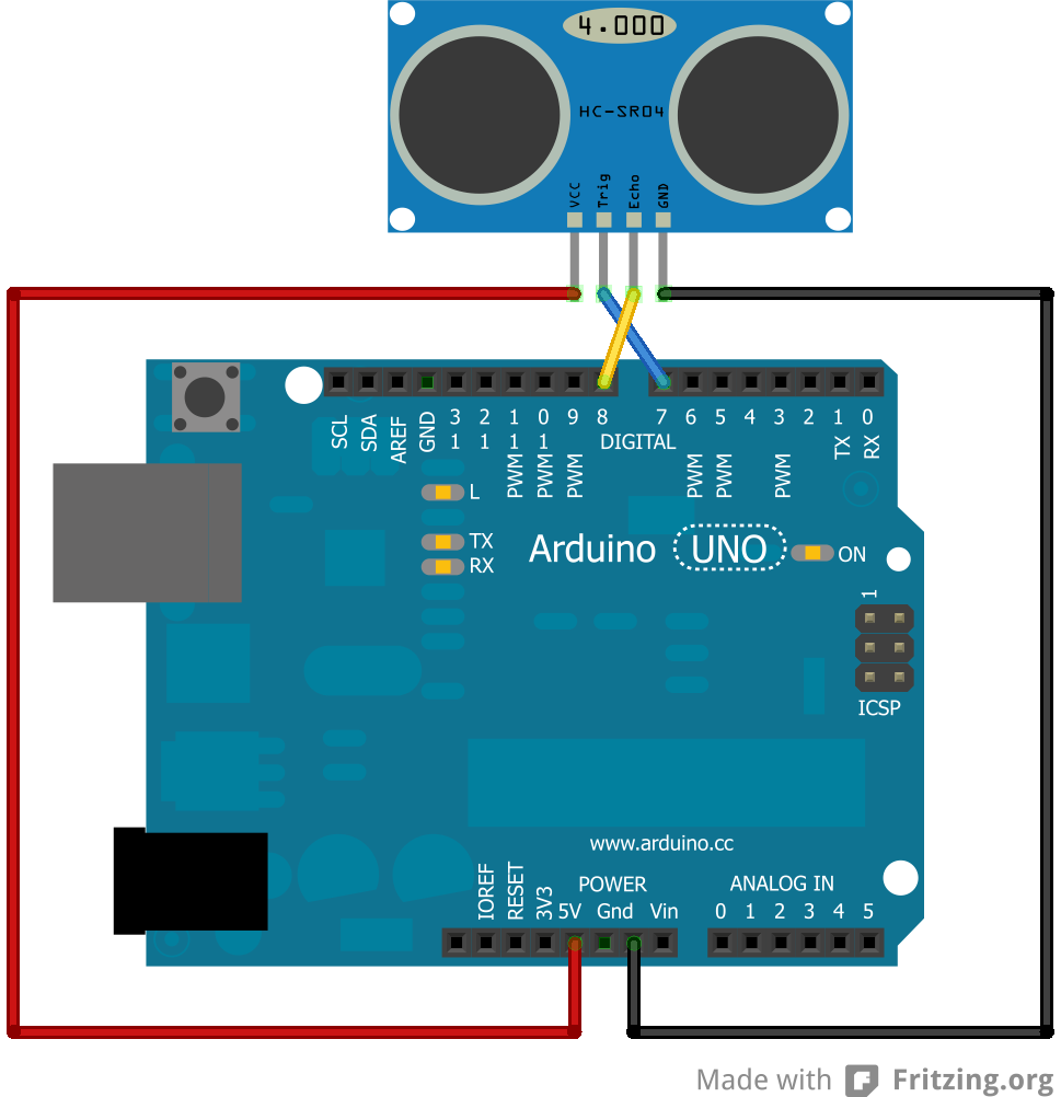
Coding
Coding the HC-SR04 is simple since the pre-existing code for the Ping may quickly be developed to work with it. For example:
//Adapted from David A. Mellis' code for Ping sensor
const int trigPin = 7;
const int echoPin = 8;

void setup() {
  // initialize serial communication:
  Serial.begin(9600);
  pinMode(trigPin,OUTPUT);
  pinMode(echoPin,INPUT);
}

void loop()
{
  long duration, inches, cm;

  digitalWrite(trigPin, LOW);
  delayMicroseconds(2);
  digitalWrite(trigPin, HIGH);
  delayMicroseconds(5);
  digitalWrite(trigPin, LOW);

  duration = pulseIn(echoPin, HIGH);

  // convert the time into a distance
  inches = microsecondsToInches(duration);
  cm = microsecondsToCentimeters(duration);

  Serial.print(inches);
  Serial.print("in, ");
  Serial.print(cm);
  Serial.print("cm");
  Serial.println();

  delay(100);
}

long microsecondsToInches(long microseconds)
{
  // According to Parallax's datasheet for the PING))), there are
  // 73.746 microseconds per inch (i.e. sound travels at 1130 feet per
  // second).  This gives the distance travelled by the ping, outbound
  // and return, so we divide by 2 to get the distance of the obstacle.
  // See: http://www.parallax.com/dl/docs/prod/acc/28015-PING-v1.3.pdf
  return microseconds / 74 / 2;
}

long microsecondsToCentimeters(long microseconds)
{
  // The speed of sound is 340 m/s or 29 microseconds per centimeter.
  // The ping travels out and back, so to find the distance of the
  // object we take half of the distance travelled.
  return microseconds / 29 / 2;
}
This code simply takes into account that the one pin on the Ping is two seperate pins on the HC-SR04 sensor.
PIR Sensor (HC-SR501)
PIR Sensor (HC-SR501)Introduction
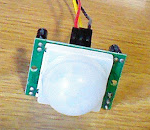
Passive Infra-Red (PIR) sensors are used to detect motion based on the infrared heat in the surrounding area. This makes them a popular choice when building a system to detect potential intruders or people in general. These sensors can take for 10-60 seconds to warm up, so try to avoid motion during that time.
Parts
- Arduino
- PIR Sensor
- Wires
Schematic
Below is the schematic for using a PIR sensor. It is fairly simple.
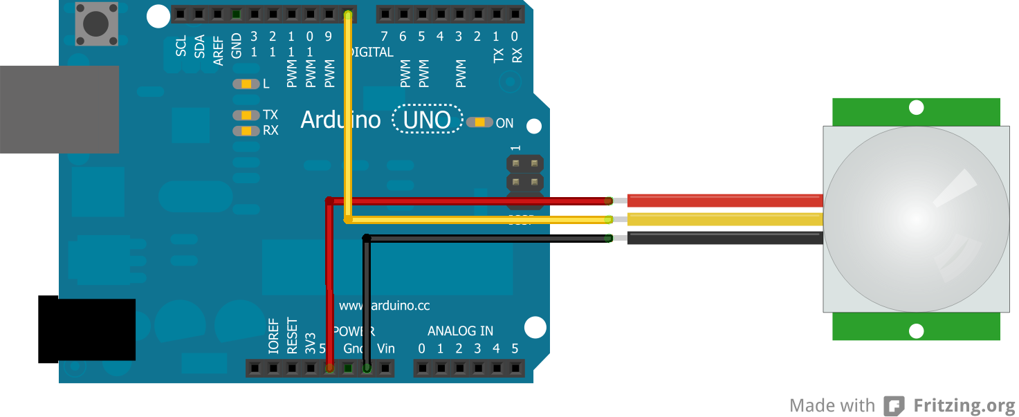
Code
Adafruit has a really good tutorial for how these sensors are used and various projects for them.
Below is the code for working with a PIR sensor. It should be noted that the PIR sensor does not respond immediately when motion stops. This has to do with the two potentiameters on the sensor.
int pirPin = 8;
int val;

void setup() {
  Serial.begin(9600);
}

void loop() {
  val = digitalRead(pirPin); //read state of the PIR

  if (val == LOW) {
    Serial.println("No motion"); //if the value read is low, there was no motion
  }
  else {
    Serial.println("Motion!"); //if the value read was high, there was motion
  }

  delay(1000);
}Linksprite JPEG Camera
Linksprite JPEG CameraIntroduction
Cameras can be used in numerous applications: survellience, hobbies, robotics, etc. They are very useful to see what is happening when a robot is moving on its own or even to just have fun with.
I got a UART camera to play around with and that I intend to stick on a robot. However, getting the code functioning on the camera was more difficult than I initially expected and there did not appear to be any good tutorials available.
I modified the code provided by Linksprite for their camera so that it will continuously take pictures rather than take one and stop. After all, if this camera is going to be used on a robot, it should be able to take more than one picture.
Adafruit and Sparkfun both provide sample code, but they required having an SD card, which I did not have at the time. This will print the images directly to the serial port and then the images can be translated with the Python code.
Parts
- TTL JPEG Camera from Linksprite
- Arduino
- 2 10K resistors
- Wires
Schematic
Below is the schematic for how to hook up the camera (Adafruit had a tutorial explaining this):

Code
There are two steps in getting a picture from the camera. The first is being able to get the proper HEX to print out on the Arduino serial monitor. The second is being able to turn all that HEX into a JPEG image.
Arduino: Take Pictures
The following code was made by altering the code provided by Linksprite to allow the camera to continuously take images. The original code took one image and stopped.
#include <SoftwareSerial.h>

byte incomingbyte;

//Configure pin 2 and 3 as soft serial port
SoftwareSerial cameraSerial = SoftwareSerial(2, 3);

int a=0x0000,  //Read Starting address
    j=0,
    k=0,
    count=0;
uint8_t MH,ML;
boolean EndFlag=0;


void setup() {
  Serial.begin(19200);
  cameraSerial.begin(38400);

  SendResetCmd();
  delay(3000);
}

void loop() {
  SendTakePhotoCmd();

  Serial.println("Start pic");
  delay(100);

  while(cameraSerial.available()>0) {
    incomingbyte=cameraSerial.read();
  }
  byte b[32];

  while(!EndFlag) {
    j=0;
    k=0;
    count=0;
    SendReadDataCmd();

    delay(75); //try going up
    while(cameraSerial.available()>0) {
      incomingbyte=cameraSerial.read();
      k++;
      if((k>5)&&(j<32)&&(!EndFlag)) {
        b[j]=incomingbyte;
        if((b[j-1]==0xFF)&&(b[j]==0xD9))
        EndFlag=1;
        j++;
        count++;
      }
    }

    for(j=0;j<count;j++) {
      if(b[j]<0x10)
        Serial.print("0");
      Serial.print(b[j], HEX);
    }
    Serial.println();
  }

  delay(3000);
  StopTakePhotoCmd(); //stop this picture so another one can be taken
  EndFlag = 0; //reset flag to allow another picture to be read
  Serial.println("End of pic");
  Serial.println();
}

//Send Reset command
void SendResetCmd() {
  cameraSerial.write((byte)0x56);
  cameraSerial.write((byte)0x00);
  cameraSerial.write((byte)0x26);
  cameraSerial.write((byte)0x00);
}

//Send take picture command
void SendTakePhotoCmd() {
  cameraSerial.write((byte)0x56);
  cameraSerial.write((byte)0x00);
  cameraSerial.write((byte)0x36);
  cameraSerial.write((byte)0x01);
  cameraSerial.write((byte)0x00);

  a = 0x0000; //reset so that another picture can taken
}

void FrameSize() {
  cameraSerial.write((byte)0x56);
  cameraSerial.write((byte)0x00);
  cameraSerial.write((byte)0x34);
  cameraSerial.write((byte)0x01);
  cameraSerial.write((byte)0x00);
}

//Read data
void SendReadDataCmd() {
  MH=a/0x100;
  ML=a%0x100;

  cameraSerial.write((byte)0x56);
  cameraSerial.write((byte)0x00);
  cameraSerial.write((byte)0x32);
  cameraSerial.write((byte)0x0c);
  cameraSerial.write((byte)0x00);
  cameraSerial.write((byte)0x0a);
  cameraSerial.write((byte)0x00);
  cameraSerial.write((byte)0x00);
  cameraSerial.write((byte)MH);
  cameraSerial.write((byte)ML);
  cameraSerial.write((byte)0x00);
  cameraSerial.write((byte)0x00);
  cameraSerial.write((byte)0x00);
  cameraSerial.write((byte)0x20);
  cameraSerial.write((byte)0x00);
  cameraSerial.write((byte)0x0a);

  a+=0x20;
}

void StopTakePhotoCmd() {
  cameraSerial.write((byte)0x56);
  cameraSerial.write((byte)0x00);
  cameraSerial.write((byte)0x36);
  cameraSerial.write((byte)0x01);
  cameraSerial.write((byte)0x03);
}
Arduino: Change Image Size
Here is code that I use when I want to alter the size of the images being taken.
/***********************
ChangeCameraSize
Jennifer Case
2/28/2013
***********************/

#include <SoftwareSerial.h>

SoftwareSerial mySerial = SoftwareSerial(2, 3);

void setup()
{
  Serial.begin(19200);
  mySerial.begin(38400);

}

int sizeChange = 0;

void loop() {
  SendResetCmd();
  delay(3000);

  if (sizeChange==0) {
    ChangeSizeSmall();
    Serial.println("Size Changed");
    sizeChange++;
  }

}

//Send Reset command
void SendResetCmd() {
  mySerial.write((byte)0x56);
  mySerial.write((byte)0x00);
  mySerial.write((byte)0x26);
  mySerial.write((byte)0x00);
}

void ChangeSizeSmall() {
    mySerial.write((byte)0x56);
    mySerial.write((byte)0x00);
    mySerial.write((byte)0x31);
    mySerial.write((byte)0x05);
    mySerial.write((byte)0x04);
    mySerial.write((byte)0x01);
    mySerial.write((byte)0x00);
    mySerial.write((byte)0x19);
    mySerial.write((byte)0x22);
}

void ChangeSizeMedium()
{
    mySerial.write((byte)0x56);
    mySerial.write((byte)0x00);
    mySerial.write((byte)0x31);
    mySerial.write((byte)0x05);
    mySerial.write((byte)0x04);
    mySerial.write((byte)0x01);
    mySerial.write((byte)0x00);
    mySerial.write((byte)0x19);
    mySerial.write((byte)0x11);
}

void ChangeSizeBig()
{
    mySerial.write((byte)0x56);
    mySerial.write((byte)0x00);
    mySerial.write((byte)0x31);
    mySerial.write((byte)0x05);
    mySerial.write((byte)0x04);
    mySerial.write((byte)0x01);
    mySerial.write((byte)0x00);
    mySerial.write((byte)0x19);
    mySerial.write((byte)0x00);
}
I just alter which function I want to call to change the size.
Python
The following code takes a text file named "outputData.txt" and turns it into an JPEG image called "binaryData.jpg". The Python code should be in the same folder that the images are in or it will not be able to find it.
The following is code for Python 2.7:
import binascii

f = open ("outputData5.txt","r")
nf = open("binaryData5.jpg","wb")

#Read whole file into data
while 1:
    c = f.readline()
    d = c.strip()
    if not c:
        break
    nf.write(binascii.a2b_hex(d))


# Close the file
f.close()
nf.close()
The following is code for Python 3:
import binascii

f = open ("outputData14.txt","r")
nf = open("binaryData14.jpg","wb")

#Read whole file into data
while 1:
    c = f.readline()
    d = c.strip()
    if not c:
        break
    nf.write(binascii.a2b_hex(bytes(d, "ascii")))


# Close the file
f.close()
nf.close()
Troubleshooting
There are many errors that can occur when dealing with the camera. I've listed the ones that seem to be common problems and that I've run into.
Banding or Artifacting
I found that banding or artifacting occurred when I tried to take larger images. There is a delay right after the SendReadDataCmd() line that can be increased to reduce banding, but I was never successfully able to take the large images without either banding or losing the last part of the image.
Python JPEG did not work
If the JPEG made from the text file did not open or was corrupted, it is probably due to the fact that the text file did not have the complete image. This could be due to the first line missing from image sent through the serial.
This has been fixed by adding a small delay after the command for the taking the photo has been sent.
Edits
12/19/2013:
Edits have been made to the code so that more than one picture will be read. - Thanks jadnexus for pointing it out
Also if you are looking to save these pictures onto an SD card, take a look at this following tutorial: http://robotic-controls.com/learn/projects/simple-security-system or http://robotic-controls.com/learn/sensors/linksprite-jpeg-camera/saving-images-sd-card-0
Saving Images on an SD Card
Saving Images on an SD CardIntroduction
Before trying this code, make sure you have ensured that your camera works because you will not be able to see what is happening with the camera while it is saving to the SD card. If you are having issues with this, please check out the Evaluation Software provided by Linksprite.
You should also take a look at this tutorial and ensure that you can in fact get a converted images before trying to save several images.
Parts
- TTL Camera by Linksprite
- SD Card Breakout Board
- SD Card
- 2 10k Resistors
- 3 other Resistors (I'm not sure if size matters, but mine were all above 1k)
- Wires
- Arduino
Schematic
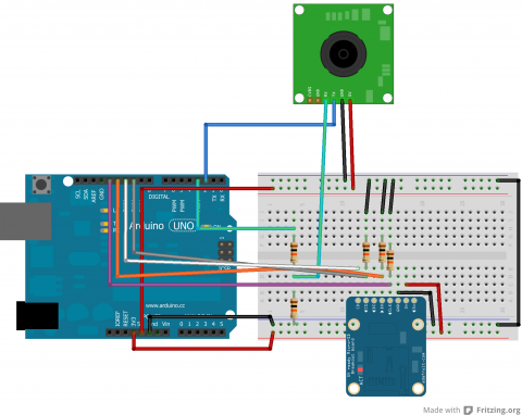
Code
Arduino
This code sets up the SD card and takes pictures, incrementing the name the file is saved as each time.
/***************************
Save Images on SD Card

by Jennifer Case
4/14/2014

Parts:
-SD Card Breakout Board
-TTL Camera

Pin 2,3 - Camera
Pin 10 - CS/D3
Pin 11 - CMD
Pin 12 - D0
Pin 13 - CLK
****************************/
#include <SoftwareSerial.h>
#include <SdFat.h>

//SD Card
SdFat sd;
SdFile myFile;
int picCnt = 0;

//Camera
byte incomingbyte;
SoftwareSerial cameraSerial = SoftwareSerial(2, 3);   //Configure pin 2 and 3 as soft serial port
int a=0x0000,j=0,k=0,count=0;   //Read Starting address
uint8_t MH,ML;
boolean EndFlag=0;

//Declare pins
const int chipSelect = 10;

void setup() {
  Serial.begin(19200); //start serial
  cameraSerial.begin(38400); //start serial with camera

  // Initialize SdFat or print a detailed error message and halt
  // Use half speed like the native library.
  // change to SPI_FULL_SPEED for more performance.
  if (!sd.begin(chipSelect, SPI_HALF_SPEED)) sd.initErrorHalt();

  SendResetCmd(); //allows camera to take pictures
  delay(3000); //delay necessary for camera reset
}

void loop() {
    //create title for images
    char photoTitle[25] = {};
    sprintf(photoTitle, "pic%d.txt", picCnt);

    //make sure file can be created, otherwise print error
    if (!myFile.open(photoTitle, O_RDWR | O_CREAT | O_AT_END)) {
      sd.errorHalt("opening photoTitle.txt for write failed");
    }

    SendTakePhotoCmd(); //take photo
    delay(200); //delay to make sure there is no drop in the data

    while(cameraSerial.available()>0) {
      incomingbyte=cameraSerial.read(); //clear unneccessary serial from camera
    }
    byte b[32];

    while(!EndFlag) {
      j=0;
      k=0;
      count=0;
      SendReadDataCmd(); //command to get picture from camera

      delay(75); //delay necessary for data not to be lost
      while(cameraSerial.available()>0) {
        incomingbyte=cameraSerial.read(); //read serial from camera
        k++;
        if((k>5)&&(j<32)&&(!EndFlag)) {
          b[j]=incomingbyte;
          if((b[j-1]==0xFF)&&(b[j]==0xD9))
          EndFlag=1; //when end of picture appears, stop reading data
          j++;
          count++;
        }
      }

      for(j=0;j<count;j++) { //store picture into file
        if(b[j]<0x10)
          myFile.print("0");
        myFile.print(b[j], HEX);
      }
      myFile.println();
    }

    StopTakePhotoCmd(); //stop this picture so another one can be taken
    EndFlag = 0; // reset flag to allow another picture to be read

    myFile.close(); //close file

    picCnt++; //increment value for next picture
}

//Send Reset command
void SendResetCmd() {
  cameraSerial.write((byte)0x56);
  cameraSerial.write((byte)0x00);
  cameraSerial.write((byte)0x26);
  cameraSerial.write((byte)0x00);
}

//Send take picture command
void SendTakePhotoCmd() {
  cameraSerial.write((byte)0x56);
  cameraSerial.write((byte)0x00);
  cameraSerial.write((byte)0x36);
  cameraSerial.write((byte)0x01);
  cameraSerial.write((byte)0x00);

  a = 0x0000; //reset so that another picture can taken
}

void FrameSize() {
  cameraSerial.write((byte)0x56);
  cameraSerial.write((byte)0x00);
  cameraSerial.write((byte)0x34);
  cameraSerial.write((byte)0x01);
  cameraSerial.write((byte)0x00);
}

//Read data
void SendReadDataCmd() {
  MH=a/0x100;
  ML=a%0x100;

  cameraSerial.write((byte)0x56);
  cameraSerial.write((byte)0x00);
  cameraSerial.write((byte)0x32);
  cameraSerial.write((byte)0x0c);
  cameraSerial.write((byte)0x00);
  cameraSerial.write((byte)0x0a);
  cameraSerial.write((byte)0x00);
  cameraSerial.write((byte)0x00);
  cameraSerial.write((byte)MH);
  cameraSerial.write((byte)ML);
  cameraSerial.write((byte)0x00);
  cameraSerial.write((byte)0x00);
  cameraSerial.write((byte)0x00);
  cameraSerial.write((byte)0x20);
  cameraSerial.write((byte)0x00);
  cameraSerial.write((byte)0x0a);

  a+=0x20;
}

void StopTakePhotoCmd() {
  cameraSerial.write((byte)0x56);
  cameraSerial.write((byte)0x00);
  cameraSerial.write((byte)0x36);
  cameraSerial.write((byte)0x01);
  cameraSerial.write((byte)0x03);
}
Python
The Python code from the camera tutorial has been revamped to allow for multiple photos to be processed at a time. This is set up to work with the naming given in the above code. The user may still have to adjust the range depending on the number of photos.
#!/usr/bin/python
# open file
import binascii

count = 0

for count in range (0,4):

    f = open ("PIC%d.txt" % (count),"r")
    nf = open("IMAGE%d.jpg" % (count),"wb")

    #Read whole file into data
    while 1:
        c = f.readline()
        d = c.strip()
        #print (c)
        #print (d)
        if not c:
            break
        nf.write(binascii.a2b_hex(bytes(d, "ascii")))


    # Close the file
    f.close()
    nf.close()
Adafruit Ultimate GPS Breakout
Adafruit Ultimate GPS BreakoutIntroduction
The Adafruit Ultimate GPS Breakout board is an excellent way to get started with GPS and Arduino. Adafruit does an excellent job providing tutorials and code for the user. I would suggest checking out their provided tutorials and code before looking elsewhere.
When I was working with the GPS, I made a few changes to the code that Adafruit provided based on how the Arduino handles floats (or doesn't handle them). The changes that I made are not particularly necessary depending on what it is being used for, but does increase the accuracy of the module on the code level. However, I suggest that you become familiar with how the unit works first before attempting to alter the code.
Schematic
Below is a schematic for connecting the GPS module to the Arduino.
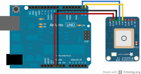
There are several pins on the breakout board that are unused in this schematic. These other pins are not necessary for communication to the GPS module, but may be useful in other respects.
How to Read Latitude and Longitude from Output
Adafruit has provided a number of different codes for a variety of applications. Specifically, I am going to go over the parsing code they provide and how to read the data for latititude and longitude. Below is the portion of the code that deals with the latitude and longitude data.
// Test code for Adafruit GPS modules using MTK3329/MTK3339 driver
//
// This code shows how to listen to the GPS module in an interrupt
// which allows the program to have more 'freedom' - just parse
// when a new NMEA sentence is available! Then access data when
// desired.
//
// Tested and works great with the Adafruit Ultimate GPS module
// using MTK33x9 chipset
//    ------> http://www.adafruit.com/products/746
// Pick one up today at the Adafruit electronics shop
// and help support open source hardware & software! -ada

Serial.print("Location: ");
Serial.print(GPS.latitude, 4); Serial.print(GPS.lat);
Serial.print(", ");
Serial.print(GPS.longitude, 4); Serial.println(GPS.lon);
This code uses the libraries that Adafruit has made available where they parse the data for the user. Here, you can see that GPS.latitude will call the float holding the latitude for the user (GPS being an instance of the Adafruit_GPS class and GPS.latitude being a property of the class). While GPS.lat will get you either 'N' or 'S' depending on the hemisphere.
Translating GPS Data
Here we need to analyze the actual output more closely. The sample output that we will be working with is a latitude reading of 1234.5678 and a longitude reading of 12345.6789.
If latitude reading = 1234.5678, then the actual latitude is read as 12° 34.5678'.
If longitude reading = 12345.6789, then the actual longitude is read as 123º 45.6789'.
This means that the floats can require some processing depending on what data is needed. Personally, I prefer turning all the data into minutes of degrees.
Thus, 12° 34.5678' = 12*60 + 34.5678 = 754.5678' and 123º 45.6789' = 123*60 + 45.6789 = 7425.6789'.
This can then be converted into meters knowing that 1' ≈ 1852 meters (going off of the fact that each degree is approximately 111km).
With this knowledge, we can take two latitude and two longitude readings and determine the difference is meters between the two coordinates. I show how to do this in a tutorial on Making a Map (pending).
Problem with Floats
If you look in the library provided by Adafruit, you will see that the data is parsed as follows (this is only a small portion of the entire code):
/***********************************
This is our GPS library

Adafruit invests time and resources providing this open source code,
please support Adafruit and open-source hardware by purchasing
products from Adafruit!

Written by Limor Fried/Ladyada for Adafruit Industries.
BSD license, check license.txt for more information
All text above must be included in any redistribution
****************************************/

// parse out latitude
p = strchr(p, ',')+1;
latitude = atof(p);

p = strchr(p, ',')+1;
if (p[0] == 'N') lat = 'N';
else if (p[0] == 'S') lat = 'S';
else if (p[0] == ',') lat = 0;
else return false;

// parse out longitude
p = strchr(p, ',')+1;
longitude = atof(p);

p = strchr(p, ',')+1;
if (p[0] == 'W') lon = 'W';
else if (p[0] == 'E') lon = 'E';
else if (p[0] == ',') lon = 0;
else return false;
All the data starts off as a string and is parsed according to what the data actually is. Here, you can see that the string containing the latitude and longitude are turned into floats with the atof(p) command.
What I have found is that Arduino was not made to handle floats well (and doubles are not different than floats to the Arduino). Arduino floats are really only accurate up to seven digits while the GPS floats have up to eight or nine digits. So, what the Arduino does is given seven accurate digits and then guesses on the other two. Below is a picture of an experiment where the string from the GPS is printed followed by the atof(p) float that the original code is producing.
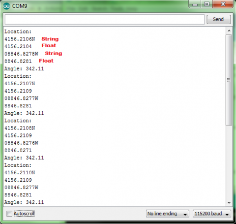
Looking at this data, you can see that the difference between the true string value and the float estimate is as large as 0.0005, which may not seem like much, but this can translate to approximately 0.926 meters (using the math from above), which could have an effect on the accuracy of the GPS. Although, admittedly, this may not be a large enough difference to matter and the approximation of meters to degrees will probably not be accurate enough to warrant the 0.926m difference. My suggestion would be to skip the rest of the tutorial if this does not matter. However, if this does matter, there is a work around to get the string values.
Altering the Library
To fix the problem, I introduce new variables to hold the latitude and longitude into the header file. This variable is a character array. Below is the line added to the header file:
char latit[10], longit[11]; //added to get strings for latitude and longitude
The code the was displayed before is then altered to look like the following:
/***********************************
This is our GPS library

Adafruit invests time and resources providing this open source code,
please support Adafruit and open-source hardware by purchasing
products from Adafruit!

Written by Limor Fried/Ladyada for Adafruit Industries.
BSD license, check license.txt for more information
All text above must be included in any redistribution

Alterations by Jennifer Case
****************************************/

// parse out latitude
p = strchr(p, ',')+1;
for(int i=0;i<9;i++) {
  latit[i] = p[i];
}
latit[9] = '\0';
latitude = atof(p);

p = strchr(p, ',')+1;
if (p[0] == 'N') lat = 'N';
else if (p[0] == 'S') lat = 'S';
else if (p[0] == ',') lat = 0;
else return false;

// parse out longitude
p = strchr(p, ',')+1;
for(int i=0;i<10;i++) {
  longit[i] = p[i];
}
longit[10] = '\0';
longitude = atof(p);
The new variables, latit and longit, can then be called similar to how the example parsing code called latitude and longitude previously. The only difference being that latit and longit are treated as strings rather than floats.
Because these coordinates are now strings, that can complicate the processing of them, so I have made a Coordinate class to handle the strings and distribute them in a more controlled manner.
Coordinate Library
The coordinate library has been developed to work with the strings that will get parsed out with these modifications to the Adafruit library. I have attached the library to this tutorial.
There are uses in this library that will not be necessary to use (such as a few constuctors). Some of them have been made to function with the construction of a map.
The main constructor that will be of interest is the following:
//constructs latitude and longitude from GPS string
//degreeLen is determined by whether you are constructing
//a latitude or a longitude. Use a degreeLen of 2 when
//constructing a latitude and a degreeLen of 3 when
//constructing a longitude.
Coordinate::Coordinate(char* gpsString, int degreeLen) {
  int i=0;
  char degree[4];
  char minute[3];
  char minflt[7];

  //Process string
  int j;
  for(j=0;j<degreeLen;j++) {
    degree[j] = gpsString[i];
    i++;
  }
  degree[j] = '\0';

  for(j=0;j<2;j++) {
    minute[j] = gpsString[i];
    i++;
  }
  minute[j] = '\0';

  minflt[0]='0';
  for(j=1;j<6;j++) {
    minflt[j]=gpsString[i];
    i++;
  }
  minflt[j] = '\0';

  //calculate for and aft
  fore = 60*atol(degree) + atol(minute);
  aft = atof(minflt); //atof is acceptable because of reduced digits
}
This method takes two arguments, a string and an integer. The string is latit or longit from the previous code. The integer lets the class know whether to process the string as a latitude or longitude. As stated previously, longitudes have one extra digit in the degree portion. So while the degree portion of a latitude is two digits long (degreeLen = 2), the degree portion of a longitude is three digits long (degreeLen = 3).
This converts everything into minutes for the user and manages it in two sections a fore part and an aft. The fore portion is the whole minutes while the aft part is the decimal parts of the minutes.
For communication purposes, there is also a method that allows printing a coordinate through the Arduino's serial:
//convert coordinate to a string and print through serial
void Coordinate::print() {
  char strFore[10], strAft[7], tempAft[6];

  dtostrf(aft,7,4,strAft);

  int i = 0;
  for(i=0;i<6;i++) {
    tempAft[i] = strAft[i+2];
  }
  tempAft[i] = '\0';

  sprintf(strFore, "%02d", fore);
  Serial.print(strFore); //this serial can be changed if using a mega or soft serial
  Serial.print(tempAft); //this serial can be changed if using a mega or soft serial
}
There are more methods that can be used as well or added to the library to fit individual needs.
ArduIMU
ArduIMUIntroduction

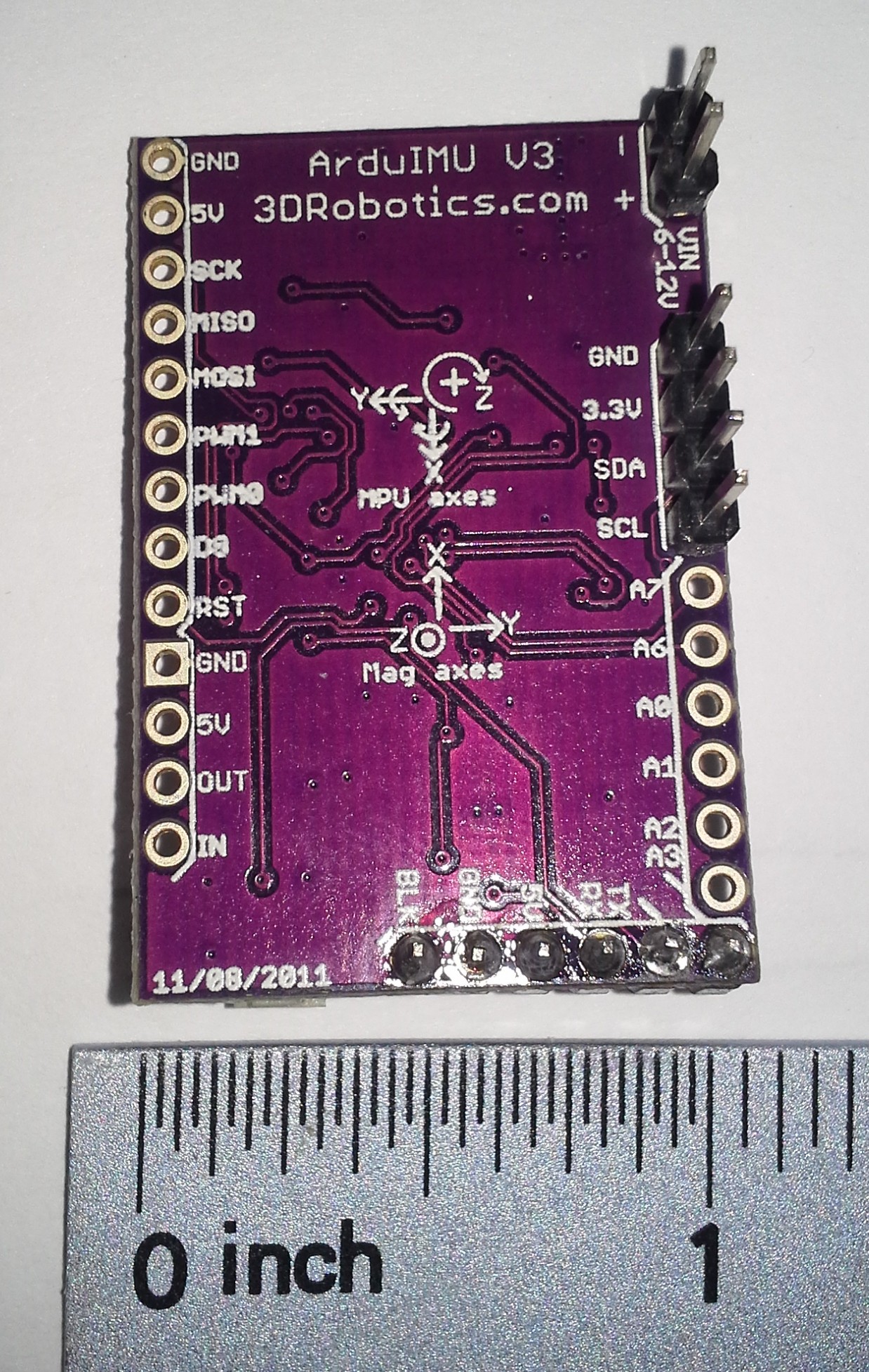
An IMU is something used to detect primarily orientation, but is a general term for an Inertial Measurement Unit. Needless to say, they can provide some vital information for mobile robots. In particular, flying robots need them since there is no way to guess orientation using wheel encoders.
An advantage to having an all-in-one unit instead of just using each of its sensors yourself is that the board can cross-check and merge the data for you. For example, a gyro gives you changes in orientation in each axis, but an accelerometer and magnetometer both send 3D directions - both in different directions too. Furhtermore, the acceleration doesn't even always point down.
One would hope that these sensors would be able to give velocity or even position information. Sadly, the sensors are just not accurate enough to be able to numerically integrate and avoid drift error. It can be possible to use the information to refine something that is capable of giving position information - like a GPS. That is partly why many of these boards include a GPS port. The other is that they are primarily used in flying drones, which usually want a GPS anyway and it is not too expensive to add the connector.
Advantages
While maybe not the highest performance IMU, I picked this sensor because I found it reasonably cheap for $50 at DIY Robotics. I am now wondering if that was an error, since it is now more expensive. For $80, it is still an ok sensor. I also appreciate the fact that it can be reprogrammed with an FTDI cable and the Arduino IDE. This allows you to change settings and add your own features. Other IMU sensors will do this too, though. A very similar is the 130$ Razor IMU available from SparkFun.
Communication
Connection
Simply connect the RX to TX and TX to RX on each end of the ArduIMU and whatever you're reading it with.
To just read the output on a linux based controller, simply run the command in bash:
sudo cat /dev/ttyAMA0
Do not use I2C
Do not bother with trying to communicate with it via i2c. Sure, i2c is nice and compact, but the compass on the board is actually using those pins and i2c. As a result, the ArduIMU is in master mode, and you cannot be the master. I wasted a lot of time trying to figure out how to read it. Do not be fooled by the fact that you can see a device on the 1E address, that is the compass. Furthermore, i2c is a little too slow to be used, so even if that wasn't a problem, it would still be a bad idea.
Format
According to the Google Code page, the output format is like this:
!!!VER:1.8.1,RLL:1.12,PCH:-0.07,YAW:34.03,IMUH:253,LAT:499247361,LON:-1193955623, ALT:3525,COG:0,SOG:0,FIX:1,SAT:9,TOW:21230400***
That's probably not what yours looks like though. To see where this comes from, find the source code here for your version, then look at Output.pde. In my version 1.9.1, the format adds slots for analog pins. My ArduIMU v3 outputs something in the format of:
Temp: 63503 Accels: 0 2 27 Gyros: 0 0 0 Mag: 397 0 -482
First of all, those spaces are actually tab characters. Also I have no idea what temp is doing, but it looks useless here since it is just changing randomly. "Gyros" is the change in orientation detected by the gyroscope. So it will say 1 or -1 usually in each - maybe a little more if it's turning fast. The accels and mag outputs are vectors pointing in the direction and magnitude of the pull in x,y, and z. The default output lacks any euler angles, quaternions, or direction cosine matrices which is disappointing.
In all likelihood, the ArduIMU is probably sending you more information than you really want. It may be worthwhile to reprogram it to give you only the information you need. Most of the common choices can be made by editing Arduimu.ino.
After some tweaking, mine now looks like this:
RLL:-7.76,PCH:3.77,YAW:145.72,IMUH:253,ACCX:-0.33,ACCY:-0.67,ACCZ:9.58,
It prints the euler angles, IMU health, and acceleration vector. I also removed anything to do with a GPS. It's fast enough that the Arduino IDE can't keep up with the serial output. It maxes out my processor and lags behind a bit. Hopefully this is not the sensor lagging, but just the extremely rapid displaying.
If you are interested, read how to program the ArduIMU below, then grab my modifications to the stock ArduIMU code at the bottom of this page.
Reprogramming
Wiring the FTDI
| ArduIMU v3 | OSEPP FTDI |
| BLK | GND |
| GND | CTS |
| 5V | VCC |
| RX | TXD |
| TX | RXD |
| ??? | DTR |
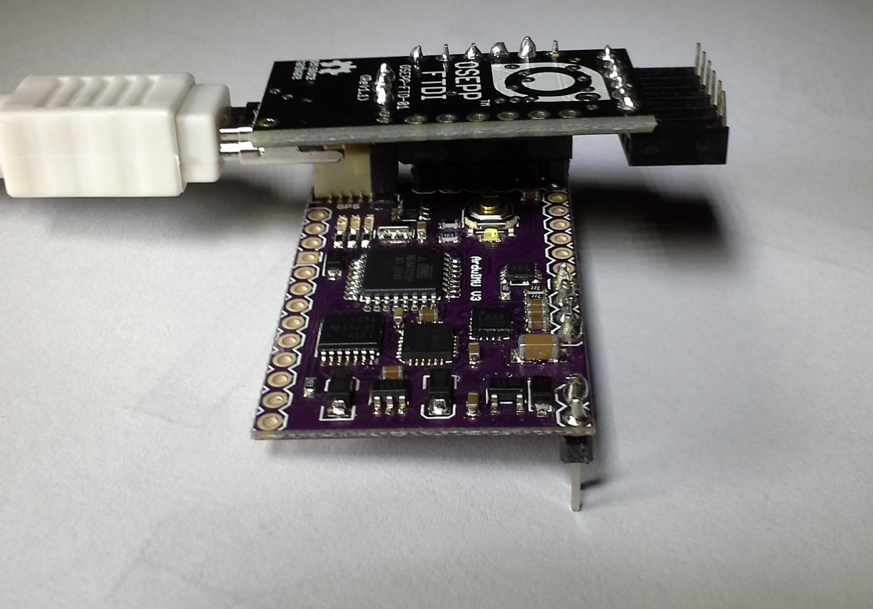
Odds are you really want the Euler angles, quaternion, or rotation matrix to be printed, since that is a lot easier to use quickly. You will need an FTDI cable. I picked the OSEPP one because it has a jumper to choose between 3.3V and 5V, which seems like an awesome feature. I picked that up for around 15$ on Amazon.
I was able to just solder some female header onto my OSEPP FTDI and plug the Arduimu in directly using the group of horizontal pins at the bottom. Also be sure to switch it to 3.3V mode. From what I've read, it seems like it may not matter, really, what the voltage is on some of the lines. SparkFun discuses it on one of their product pages. I'm betting there is some truth to that since there is a 5V pin.
Also, depending on the FTDI cable you have, there is a possibility that you might need to press the reset button yourself. The auto-reset feature is apparently somewhat new and will also depend on whether it is wired up correctly.
It is also recommended that you power the ArduIMU with something other than the FTDI cable while programming. So, be sure to connect an additional power source to the Vin or 3.3V pins.
Makefile
From there, you just need to configure the makefile. Run make configure to configure make, then run make upload to compile and upload it. My Makefile looked like this, but I never actually got it to work:
BOARD	=	atmega328
ARDUINO_DIR  = /usr/share/arduino
TARGET = Arduimu
ARDUINO_PORT = /dev/ttyUSB0
ARDUINO_DIR  = /usr/share/arduino
AVR_TOOLS_PATH = /usr/bin
include ../AP_Common/Arduino.mk
I also found that you might need to add #define ARDUINO 103 to the code in order to fix a few compile errors. This was probably a sign of some bigger problems though.
Arduino IDE
It is actually easier to just use the Arduino IDE.
Copy the Library folder from the zip of the code you download to your sketchbook Library folder.
Open the Arduimu.ino file in the Arduino IDE.
Simply select the correct Serial port - on my Ubuntu Linux system it was /dev/ttyUSB0. Then select a compatible board - the Arduino Nano w ATmega328. The programmer is just the standard AVRISP mkII due to the serial interface selected. On windows, the setup process for the FTDI cable may be more in depth. The ArduIMU google code page has some more information on it. You might be better off just looking up your specific FTDI cable first though.
With the FTDI cable on my system, you can actually just open the serial monitor and set the baud rate to 38400. I didn't know that at first and was hooking it up to a raspberry pi to see the output. This is a lot easier.
Fixing Bugs
If you get this error:
AP_Common/AP_Common.h: In function ‘int strcasecmp_P(const char*, const prog_char_t*)’:
AP_Common/AP_Common.h:108:38: error: ISO C++ forbids declaration of ‘type name’ with no type [-fpermissive]
AP_Common/AP_Common.h:108:38: error: ISO C++ forbids declaration of ‘type name’ with no type [-fpermissive]
AP_Common/AP_Common.h:108:32: error: expected primary-expression before ‘const’
AP_Common/AP_Common.h:108:32: error: expected ‘)’ before ‘const’
Just add this line to the top of Arduimu.pde. Somewhere above the #include statements:
typedef char PROGMEM prog_char;
I also went around and removed FastSerial and just left it with the regular serial. I'm guessing there was a good reason for making their own, but it was extremely annoying that they had to use the same variable name as the regular Serial object. I couldn't get it to compile due to it.
Configuring Output
There are a bunch of #define statements in the Arduimu.ino file. Those can be changed to modify a lot of the important features. I had to change just about every one of the settings to get what I wanted. This is the result:
// Enable Air Start uses Remove Before Fly flag - connection to pin 6 on ArduPilot
#define ENABLE_AIR_START 0  //  1 if using airstart/groundstart signaling, 0 if not
#define GROUNDSTART_PIN 8    //  Pin number used for ground start signal (recommend 10 on v1 and 8 on v2 hardware)

/*Min Speed Filter for Yaw drift Correction*/
#define SPEEDFILT 0 // >1 use min speed filter for yaw drift cancellation (m/s), 0=do not use speed filter

/*For debugging propurses*/
#define PRINT_DEBUG 0   //Will print Debug messages

//OUTPUTMODE=1 will print the corrected data, 0 will print uncorrected data of the gyros (with drift), 2 will print accelerometer only data
#define OUTPUTMODE 1

#define PRINT_DCM 0     //Will print the whole direction cosine matrix
#define PRINT_ANALOGS 0 //Will print the analog raw data
#define PRINT_EULER 1   //Will print the Euler angles Roll, Pitch and Yaw
#define PRINT_GPS 0     //Will print GPS data
#define PRINT_MAGNETOMETER 0     //Will print Magnetometer data (if magnetometer is enabled)

// *** NOTE!   To use ArduIMU with ArduPilot you must select binary output messages (change to 1 here)
#define PRINT_BINARY 0  //Will print binary message and suppress ASCII messages (above)

// *** NOTE!   Performance reporting is only supported for Ublox.  Set to 0 for others
#define PERFORMANCE_REPORTING 0  //Will include performance reports in the binary output ~ 1/2 min
Furthermore, I think it is weird that they would have an option to print the magnetometer, but not the accelerometer. It seems like acceleration would be a lot more important for a controller, since the magnetometer's information, I assume, is already built into the orientation output.
Modifying the Output
To add the acceleration information, I just modified Output.ino (line 61 to 68)
#define ACCELCONVERSION 0.0023147712
Serial.print("ACCX:");
Serial.print(Accel_Vector[0]*ACCELCONVERSION);
Serial.print(",ACCY:");
Serial.print(Accel_Vector[1]*ACCELCONVERSION);
Serial.print(",ACCZ:");
Serial.print(Accel_Vector[2]*ACCELCONVERSION);
Serial.print(",");
The ACCELCONVERSION constant was chosen by expermentation to convert to the output to m/s2 using the following method:
- Print the values of the Accel_Vector
- Leave the ArduIMU on a flat level surface
- Take a few samples of the acceleration on the z axis (Accel_Vector[2])
- ACCELCONVERSION = 9.81 / SampleAverage
Repeat the process, if necessary, until the output is correctly calibrated to the known gravitational constant.
It is perhaps better practice to instead do the conversion on the recieving device, since the values would be more compact and accurately sent over serial. On the other hand, it makes the ArduIMU more easily accessible if the units are known. To convert the acceleration data on the reading device, the proceedure is the same.
Parsing the Serial Input
While you could read this sensor with an Arduino, it already is an Arduino. Furthermore, the mere fact that you're using it probably means you want to analyze a 3D system. You're probably going to need some more firepower. Something like a Raspberry Pi, or a BeagleBone. A Raspberry Pi processor is at least 1000 times faster than an Arduino, and a BeagleBone Black is at least twice as fast as a Raspberry Pi and has more pins.
With these faster devices, you get to use a higher level programming language like Python or Node.js. Both will run Python, so it is a good choice for speed and portability.
Joystick
JoystickIntroduction
Joysticks have become a common tool among various devices, such as gaming controllers. They can be an interesting addition to projects as well. Joysticks are fairly simply components that use two potentiameters to give the readings from two axes. They may also include a button to see if the user has clicked the joystick.
Schematic
Below is a schematic showing how the joystick connects to an Arduino.
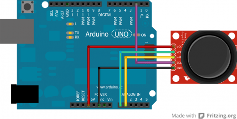
As stated previously, a common joystick will use two rotating potentiameters and a button. The potentiameters are analog while the button is digital.
Code
The following code shows how to read the various components of the joystick.
int verPin = A0;
int horPin = A1;
int selPin = 2;

void setup() {
  pinMode(selPin, INPUT);
  digitalWrite(selPin, HIGH);
}

void loop() {
  int verPos = analogRead(verPin);
  int horPos = analogRead(horPin);
  boolean selBtn = digitalRead(selPin);
}
Getting the information from the component is really simple, but a lot of fun projects can be done with joysticks.
Wireless Communication
Wireless CommunicationPreface
A mobile robot shouldn't be hindered by power cables and data connections. So, when making a mobile robot, it is often necessary to communicate with it wirelessly.
Many forms of wireless communication are still, essentially, serial. So, converting a project from being tethered by a USB to being completely wireless is simply a matter of getting a good battery, and the right wireless accessories (you'll need two ends).
XBee Configuration
XBee ConfigurationIntroduction
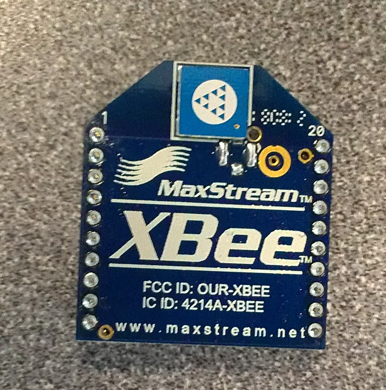 XBees are one form of wireless communication. They use radio frequency to communicate over long distances (from 100m to over 1500m.) They do have issues transmitting through walls and through obstacles, but that is common to many types of wireless communication.
There are two main types of XBees: Series 1 and Series 2 . Series 1 XBees do not say that they are Series 1 on them, but that is one way to determine that they are Series 1. Series 1 is generally easier to use and configure. It is also faster than Series 2. The advantage of the Series 2 XBees is that there is a lower current draw.
This tutorial will go through the configuration of Series 1 XBees.
Configuring the XBees
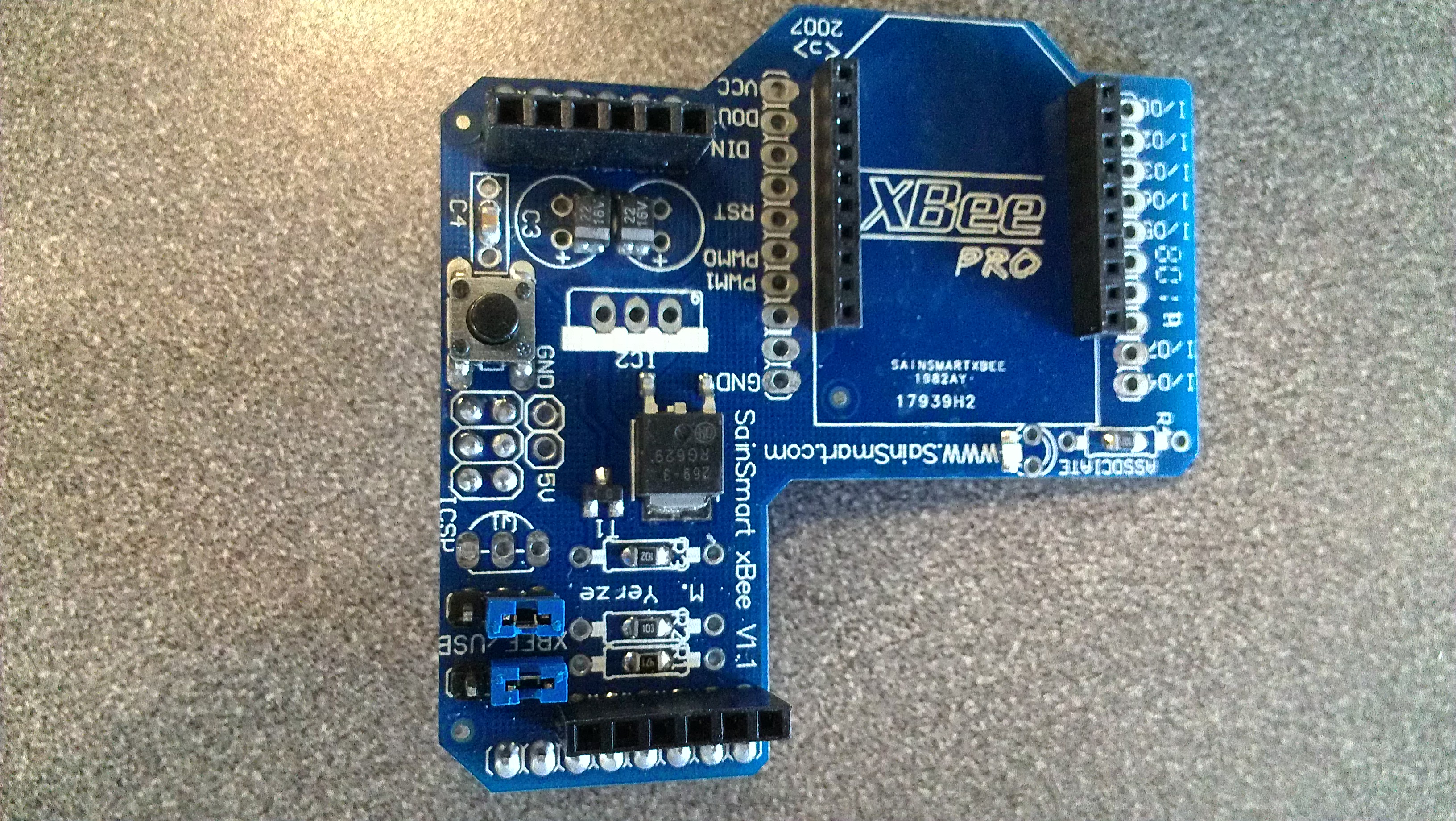
The figure below shows what a typical XBee looks like.
Before getting XBees to communicate with each other, it may be necessary to configure. This tells the XBees which channel they will send or receive data from and which XBee they are communicating with. Configuring can be done easily with the use of a software called X-CTU . The X-CTU program can be found under Diagnostics, Utilities and MIBs .
There are two diff erent boards that can be used for confi guration. The XBee Explorer USB board is available through Sparkfun . The SainSmart XBee Shield module , as seen below, can also be used to con figure XBees with the use of an Arduino.
Note: If the XBee Shield module is being used, put your Arduino in reset, which means run a wire from reset to ground as seen below, and make sure the jumpers on the shield are set to USB. Put the shield on the Arduino.
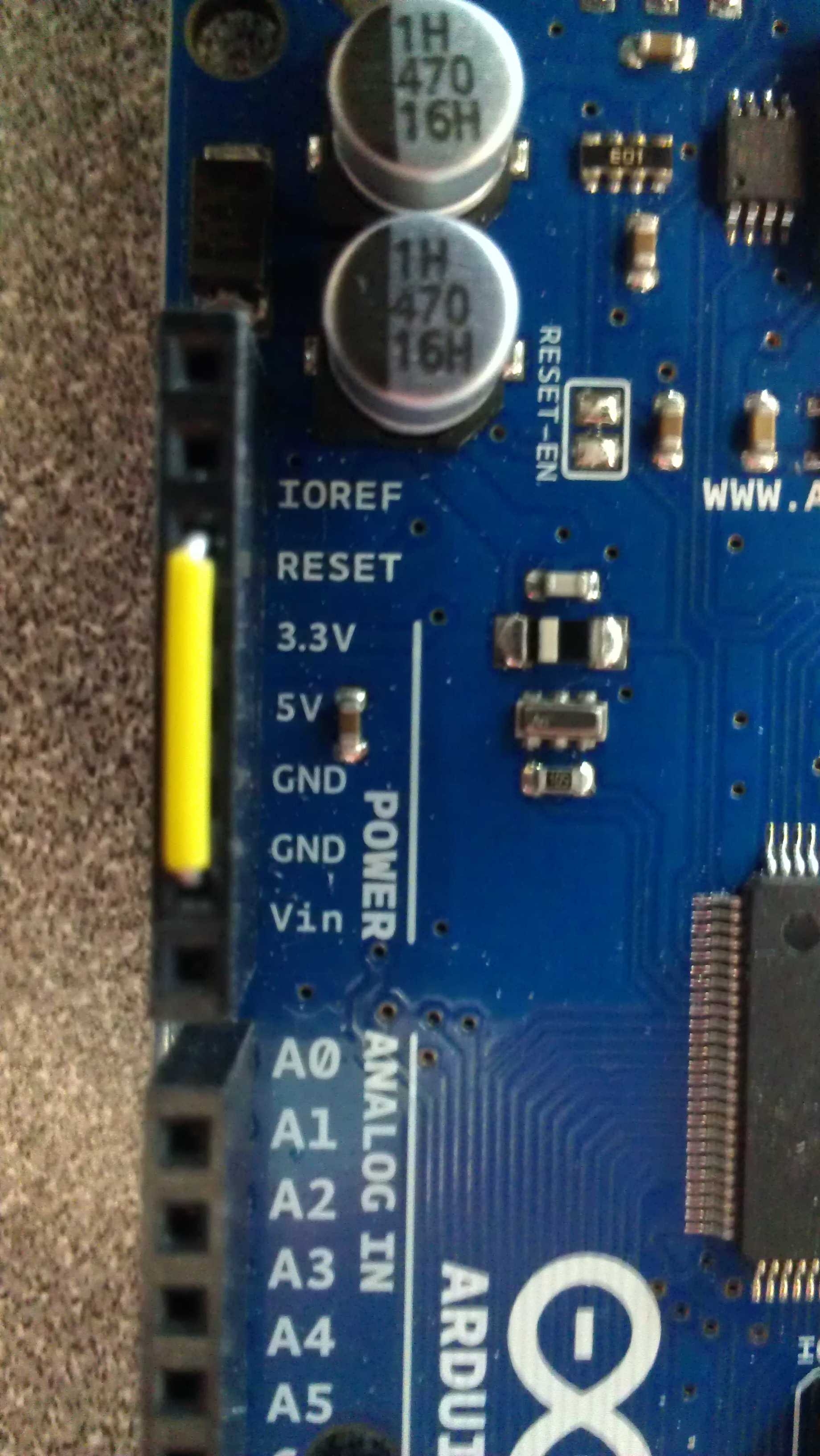
Plug either the Arduino and shield or the Explorer board into the computer and then start the X-CTU program. The program should be able to open up and display a screen similar to the one below.
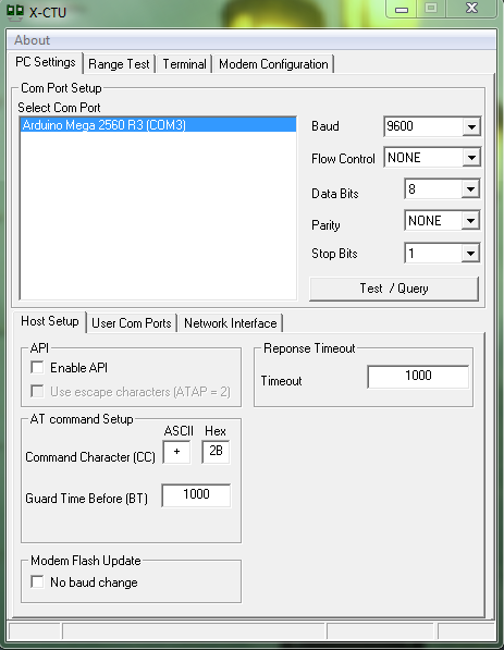
Notice how it recognized the product being used. It should be noted that this is the PC Settings tab. In this tab, there should be a Test/Query button on the right. An example of the screen print out can be seen below.

From this screen, the Serial Number High (SH) and Serial Number Low (SL) can be found for the Arduino. This can be done by breaking apart the Serial Number. Each SH and SL can be eight hexadecimal digits long; however, the SL will be eight long and the SH can be shorter. For example, the above figure shows a SH of 13A200 and a SL of 404AC735.
Go to the Modem Con guration tab and select the Download new versions button. Wait for the download to fi nish and then select the Read button. This will read some of the data in the XBee, as seen below. If the XBee has not been con figured before, it will not read the SH or SL from it, so that information must be obtained from the Test/Query screen. Repeat these steps with the other XBee and make sure to know which SL and SH belong to each XBee.

Now configuration can begin:
- Select one of the XBees, which will now be referred to as XBee 1, and plug it back into the board; the other XBee will now be referred to as XBee 2.
- Read XBee 1 to make sure it has the expected SL and SH values. This should also set the Modem to the Modem of the XBee.
- Change the Destination Address High (DH) of XBee 1 to the SH of XBee 2.
- Change the Destination Address Low (DL) of XBee 1 to the SL of XBee 2.
- This is not necessary to change, but in order to avoid interference with other XBees, it would be prudent to change the Pan ID (ID) of the XBee as well to a number below FFFF, such as 2222.
- Select Write after all the changes have been made.
- Unplug XBee 1 and plug in XBee 2.
- Read XBee 2 to make sure it has the expected SL and SH values. This should also set the Modem to the Modem of the XBee.
- Change the DH of XBee 2 to the SH of XBee 1.
- Change the DL of XBee 2 to the SL of XBee 1.
- If you changed the ID of the XBee 1, make sure you change the ID of XBee 2 to the same value.
- Select Write after all the changes have been made.
The following figure gives a graphical representation of this.
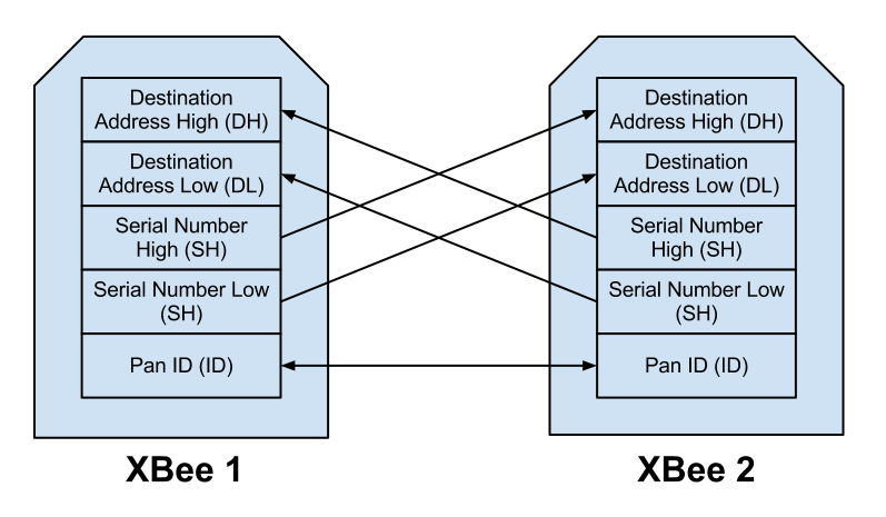
The two XBees should now be configured to communicate with each other. This means that coding to connect the two may now be done and the wireless communication is ready to go.
XBee Communication
XBee CommunicationIntroduction
XBees are a very simple way to enable wireless communication. Using wireless communication will expand the possibilities of a project, and is practically a necessity for a robot.
Two types of XBee communication that will be discussed are Arduino-Arduino communication and Arduino-Computer communication.
XBees cannot both send and receive data at the same time. If caution it taken, data should not be lost due to this fact.
Arduino-Arduino Communication
If the Arduino shield is being used, the jumpers should be set to USB mode when programming the Arduinos and then should be set to XBee mode when the programs are run.
Coding with XBees is simple because they can simply be coded using the familiar serial code.
To send from an XBee:
Serial.print("Send to other XBee");To receive from an XBee:
int incomingByte;

if (Serial.available() > 0) {
  incomingByte = Serial.read();
  Serial.print(incomingByte);
}
Arduino-Computer Communication
The above code for sending and receiving data from an XBee is valid for the code on the Arduino.
If an Arduino with a shield is used to connect to the computer, the code put on that Arduino is a simple blank sketch:
void setup() {}

void loop() {}
The blank sketch bypasses the microcontroller and allows the data to flow through to the computer. For the XBee shield that is connected to the computer, the jumpers should be placed on USB mode since the data is going to be sent through the USB to the computer.
The data coming through can then be seen in the serial monitor. The data sent from the serial monitor will then be sent through the XBee to the other one on the Arduino.
If the serial monitor is not an attractive option, python code can also be used to handle the serial coming through. Creating a GUI may be a best option to handle the serial coming into the computer.
Programming
ProgrammingPreface
It turns out, making robots requires a lot of programming. The more autonomous, the more advanced the program.
Here are some conceptual lessons in programming. Odds are you'll find them useful when programming for a robot.
Introduction to C++ Programming
Introduction to C++ ProgrammingIntroduction
Programming is becoming more useful in a variety of fields. There are a lot of uses, but we are most interested in robotics applications. Microcontrollers like the Arduino are programmed in C++, which is undoubtedly the most widespread language. It is powerful, fast, and easier to use than some earlier languages. However, it is not the easiest language to learn. It has a very strict syntax and the errors can be hard to understand. It is still worthwhile to learn due to its usefullness.
If you are just interested in learning programming in general, I highly recommend looking at Codecademy, which is an excellent interactive environment for learning for the first time. Of their courses, Javascript is most similar to C++, but Python is the easiest and most powerful choice.
The Basics
Programming is actually quite simple. There are really only a few things that you need to know to get started.
- Data is stored in "variables"
- The right hand side of an equals sign goes into the storage with the name at the left
- There are different kinds of variables that contain different kinds of information
- A program is executed top down
- Each line is terminated by a semi colon
- Comments are ignored ( lines that begin with two slashes: // )
- There are three fundamental actions that alter the top-down flow:
- Conditions: do something only if something else is true
- Loops: do something repeatedly
- Functions: do a group of things and get a result
Try It Yourself
Set up a Development Environment
You need a place to code! Code::Blocks is a good place to start, but there are dozens of options. Microsoft Visual Studio Express is actually free to use, but there are free-er (open source) options too.
To install Code::Blocks, go here and choose the mingw-setup.exe. The mingw is important because it includes a compiler, which turns the program that you can write and read into something that your computer can actually run. Install the program like you would any other.
Use the Development Environment
Now get started! Run Code::Blocks. Make a new source file (File > New > Empty file). Put this simple program in there.
#include <iostream>
using namespace std;

int main() {
    // anything preceeded by a // is a comment and ignored by the computer
    // code goes in between the above and below { and }

    cout << "HELLO WORLD!"; //shows "HELLO WORLD!" in a command prompt
}
Be sure to pay attention to things like semi colons and brackets. It won't work if you miss one.
All this program does is print out the words HELLO WORLD to the terminal or command prompt whenever it is run.
Try it out! Hit the green button "Run" triangle at the top of the Code::Blocks to compile and run it.
Fundamentals of Programming
These are the five things that you need to know to program, that's all!
- Variables are places you store data
- Operators do things to data
- Conditions check data, and do something if it is a certain way
- Loops let you repeat actions
- Functions let you group actions together so you can re-use them and return a result of those actions
Variables
Variables are not at all like the variables you find in math. These are just named places you put information. You can change the contents of what's at a name, which is what "varies" about it. You can only store a few kinds of information, and they are:
int: An integer can hold a whole numberchar:A character can hold a letter or symbolfloat: A floating decimal point can (inaccurately) hold really large and really small numbers (and decimals)
First, you need to declare the variable. You start by saying the type of data it can contain. When this is done in C++, it is uninitialized - meaning that you have no idea what it contains. You might want to assume, for example, that a number starts at 0 when you declare that you want to use it, but you have to explicitly say that.
Then, you assign contents to the variable. The contents can be pre-defined by you, or you can get the contents of another variable, or even read it in from somewhere else.
Arrays
All variables can be be arrays. An array is a series of variables put next to each other. You specify the array with the array's name, and which item in the list of its variables you want with a number in brackets after it. The first item in the list is at the number 0. You have to say how large an array is when you declare it.
An array with its index behaves exactly the same as a variable would
int numbers[3];     // declare the array (list) of integers (whole numbers)
numbers[0] = 100;   // fill the first item in the list with a 100
numbers[1] = 200;
numbers[2] = 300;   // fill the last item in the list with a 300
Swap Example
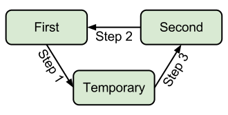
Swapping variables is an excercise of the very important concept of storage and variables.
Imagine you have two cars in a parking lot you want to swap parking spaces with. You're the only valet and you want to swap the two cars so they match colors with the other cars because you're bored. In order to swap the cars, you'll have to move one car to a third parking space temporarliy while you move the other into the newly vacated space. It's a similar solution to a slightly different dilema. If you were to try to swap directly (without a temporary) with the cars, you would smash one into the other, but in a program you would end up two copies of the same data.
Start by declaring two variables you want to swap, and a temporary variable. Then assign something different to the two variables. Store the contents of one of those into the temporary. This is extremely important because otherwise the contents of "first" will be lost in the next step, which moves the contents of "second" into the "first" variable. Finally, the temporary variable moves the former contents of "first" into the "second" variable.
| Swap Integers | Swap Floats | Swap Characters | Swap Array Elements |
|---|---|---|---|
//declare integers int first = 100; int second = 200; int temp; //next shift data // Step 1 temp = first; // Step 2 first = second; // Step 3 second = temp; |
//declare floats float first = 1.0; float second = 2.0; float temp; //next shift data // Step 1 temp = first; // Step 2 first = second; // Step 3 second = temp; |
//declare chars |
int num[2]; |
As you can see, it is the same proceedure to swap the contents of variables, regardless of data type.
Operators
An operator is a letter or couple of letters that just say "do something" to a variable. For example, a + sign is an operator that says add two numbers. There are actually not that many operators. Operators do very simple actions. More advanced actions can usually be broken down into a series of these simple actions. Don't worry, you don't have to remember it all at once, but they are fairly intuitive.
- Storage
=The assignment operator copies the contents at the right into the variable at the left.- Math - modify the data
+, -, *, /all perform math operations the way you would expect++and--increment or decrement a variable by 1- Really,
number++is just a shorthand fornumber = number + 1 +=and-=are shorthand for addition and subtraction then asigment- Again,
number += 10is just a shorthand fornumber = number + 10 - Logical - Checks something about the data
==The equivelence operator checks to see whether the contents of the right and left are the same- Be careful not to confuse it with the assignment operator
= >,<,>=,<=all check for inequalities- ! also called "not" inverts the condition, making a false into true, and a true into false
&&,||also called "and" and "or" respectively are ways to check multiple conditions at once
Operator Usage Example
// declaration
int number = 1;      // create space for and store a whole number: 1

// arithmetic
cout << number;      // prints 1
cout << number + 2;  // prints 3 (1 + 2 = 3)
cout << number;      // prints 1. "number" did not change! Nothing was assigned;

// assignment
number = number + 2; // add 1 to 2, then assign that result into number
cout << number;      // prints 3. "number" changed! It was assigned a new value

// increment
number++;            // adds 1 to the former contents of number (3)
cout << number;      // prints 4 (3 + 1 = 4)

// logical operations
cout << number == 4; // prints a 1, which means true. "number" does equal 4.
cout << number > 4;  // prints a 0, which means false. Number is not greater than 4
Conditions
Conditions, as the name suggests, will check to see if something is true, then react based on that information. Conditions are used in if statements, and evaluated in loops (more on that later). They are either true or false.
Use the logical operators to construct your conditions. You can check for equalities, inequalities, and chain these conditions together with and (&&) and or (||) operators.
An if will only execute the code within its {brackets} if th condition is true. An else if's code will only get executed if the preceeding "if" was false and it's condition is true. An else's cod will only be executed if the preceeding if and else ifs are all false.
Guessing Game Example
// Ask for a letter from the user.
cout << "I want to play a game. I am thinking of a letter a through z. Guess: ";

char letterRead;   // declare space for an character
cin >> letterRead; // read input for the command prompt and store it in letterRead

// use a condition to see if their guess was correct
// note the use of the equivelence checking operator (==), not assignment (=)
if ( letterRead == 'm') { // m was the correct letter
   cout << "Correct! You win!";
}

// if the character is after 'z' or it is before 'a'
// then the character was not a lower case letter a through z
else if ( letterRead > 'z' || letterRead < 'a') {
   cout << "That was not a letter...";
}

// the character was a letter, but it was not the correct letter
else {
   cout << "Wrong. You lose.";
}
Loops
Loops run code on repeat until a condition says "stop".
char continue = 'y';
// the first time, the loop will run since it starts with 'y'
while ( continue == 'y' ) {
    //do something here until the user says 'n'

    cout << "Continue? (y/n)";
    cin >> continue;
}
Most loops simply count a number by one so you can go through all the possibilities in a range because loops are most useful for doing something to all of the elements in an array. As a result, a shorthand has been made. Compare:
| While Loop | For Loop |
|---|---|
int numbers[10]; |
int numbers[10]; |
Both loops essentially do the same thing. They print the random, uninitialized contents of the "numbers" array with a newline ('\n') at the end of each element.
Functions
Functions group operations into a name. You run the operations by saying the name of the function followed by (). You can give the function parameters by passing them between the parenthesis. Maybe most importantly, a function returns the results of its group of actions once it is done.
Note tha main is a function. It is run by default when you run the program. It also is an int. The value returned by main is actually an error code.
int myPow(int base, int exponent) {

   // powers of 1 and negative powers will return 0, regardless of the base
   if ( exponent <= 0 ) {
       return 1;
   }

   int result = base; // create a place to store the result

   //multiply the result by itself "exponent" number of times
   for( int i = 1; i < exponent; i++) {
      result *= base;
   }

   return result; //return the product of the exponent
}

int main() {
   cout << myPow(5,0); // prints 5^0, which is 1
   cout << myPow(1,5); // prints 1^5, which is 1
   cout << myPow(2,4); // prints 2^4, which is 16
   cout << myPow(2,5); // prints 2^5, which is 32
   cout << myPow(3,3); // prints 3^3, which is 27

   return 0; // there was no error
}
Conclusion
Congradulations! If you understood most of this, you are now qualified to do quite a few awesome things with an Arduino. Check out our tutorials for tricks with Arduino and using sensors with an Arduino.
There is still more to know, but it gets easier from here. In larger programs you will need to worry about where a variable can be accessed from. Also, classes and structures help you organize your data and are extremely powerful when you know how to use them.
Data Storage
Data StorageAnalogy
Storing data on a computer is a lot like storing things in a warehouse. If you keep track of where you put things well enough, it shouldn't matter how much stuff you have stored.
Imagine an empty warehouse. If you store something in it, it doesn't really matter if you keep track of it because it's easy to look for it again. If the warehouse were full, you better keep track of where you put your stuff or you'll have to look everywhere for it. In a warehouse, you would probably write down an isle number, a shelf number, and maybe a pallet number. This way, you don't look through all the things, just go directly to the right place.
Warehousing Techniques
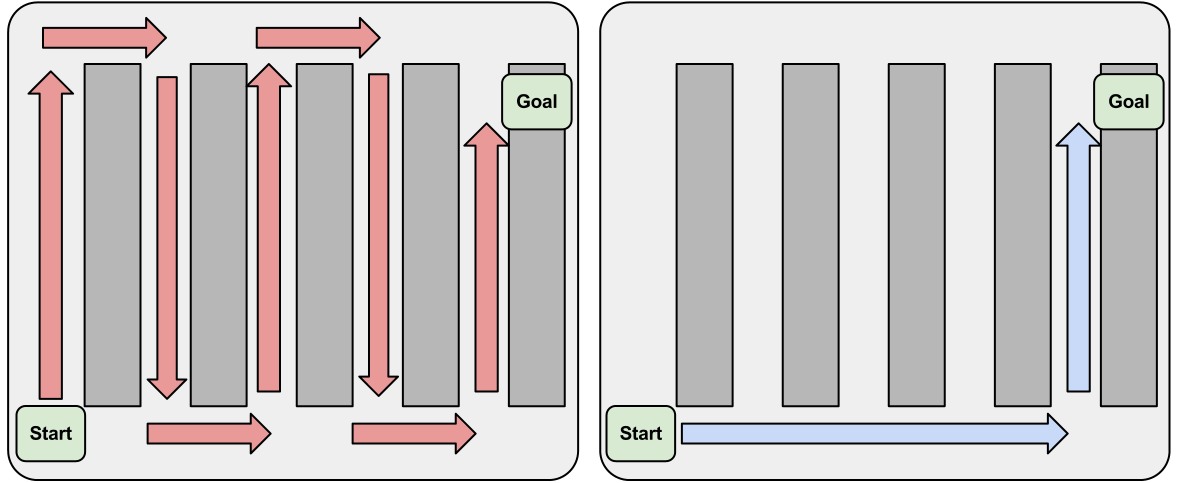
Unindexed Storage (left), Indexed Storage (right)
So, by keeping records of stuff as it comes in, you reduce the time it takes to look for it later. It is like what keeps your computer from getting slower when you add files to it. Your file system is the guy in the warehouse putting your files somewhere, and keeping track of where it should be so you can find it again quickly. This is how Google can search the entire internet in just milliseconds - by using a process called indexing. More data doesn't have to be slower. This is why it is important to understand how to store your data efficiently.
Linked Lists
A lot of the time, you have a specific order to things, but might want to be able to add or remove stuff at the beginning or in the middle. With an array, you would have shift the contents around to keep it in the right order. With a linked list, you just change a few pointers to change the order.
There are two main kinds of linked lists: queues and stacks. It's actually pretty easy to remember which is which. A queue is like the line at the grocery store (which in Britain, is actually called a queue), and a stack is like a stack of trays.
A queue is First In First Out (FIFO). Things are handled in the order they are receieved. This is extremely useful for things like buffers.
A stack is Last in First Out (LIFO). It's mostly useful for coming back to things if you get interrupted or retracing your steps.
The two are extremely similar in concept and implementation, but a queue is more common and more useful. A lot of programming languages and environments have pre-built versions of both these which are nice and reliable. Some examples of queue libraries: Python, C++ STL, and Arduino C. These queues are great because they dynamically expand at runtime, so they use only as much space as they need.
Using a Queue
Push: New things can be added to the end of the queue with a
queueName.push( newThing )
Pop: Once there are things waiting in the queue, you get the next one in line out by saying:
value = queueName.pop()
This both stores the value of the next one in line to the variable at the left, and removes it from the list, so be careful not to accidentally remove something before you're really done with it.
Peek: If you don't want to delete the next thing waiting, but still want to see what it is, you can take a peek at it with
value = queueName.peek()
Indexing
An index is like the index at the front or back of a book. You have a condensed table of things you might look for and a place to jump to. Indexes are great for speedy searches through data. The problem is that they require the data to be unique - otherwise you wouldn't know which place to jump to. You could try having a list of places to jump to, but at that point it gets complicated and you lose a lot fo the speed benefit that makes indexing so great. If you find yourself considering indexing to effectively organize your data, you might want to consider using a database instead.
If you want to keep it light or do it yourself, you may need to implement a hash table. A hash table is a way to look things up in constant time - which means it takes the same amount of time to find something no matter where it is.
Databases
In general, you will probably not be using a database on a robotic system. Many of the existing database applications would simply not work on an arduino. You could, however, put one on a raspberry pi.
It might be easiest to think of a database like a spreadsheet. Each column stores a specific kind of information. Unlike a spreadsheet, each row usually has a unique identifier, which can be used as the index. An index can be quickly found in the table. These are particularly useful for "merging" tables (the operation is called JOIN).
Databases are powerful tools for filtering complex data, and continue to be efficient on larger scales.
An example of potential use in a robot is that you could receive sensor readings with a raspberry pi, and store them in a database for analysis. Unless they data needs to be accessed during operation, it might just be easier to store the data to a file in a Comma Seperated Value sheet (CSV), which could then be opened in a spreadsheet program.
LaTeX
LaTeXIntroduction
LaTeX is a typesetting system. It's an easy way to make very professional looking papers. In fact, many academic books were written in LaTeX. You can usually tell by looking in the first few pages. Somewhere it might say "Typeset in LaTeX".
LaTeX cannot really help you build a robot, but if you are building a robot either professionally or academically, you will need to present your project in a technical and professional manner with a well-polished document.
LaTeX basically takes a plain text file with special syntax and compiles that syntax into a well-formatted PDF.
Installation
From anecdotal experience, the best and most common way to write LaTeX documents is Texmaker. Other LaTeX editors exist, but they all use the same LaTeX engine, so there really is not that big of a difference between them. Some have different ways to preview the document or wizards to make more complex features. Really, all you need is a plaintext editor and a command prompt, but an editor provides a more streamlined experience.
The installation is somewhat large - about a gigabyte. On Windows and Mac it is a multi-step process to install the LaTeX editor and the compiler. On Ubuntu simply run: sudo apt-get install texmaker
Using Texmaker
Really, all you need to do is make a new document, add some bare minimum structure to the document, and hit the F1 key on your keyboard or the "quickbuild" arrow at the top. Most of the other buttons are just there to help you find more features of latex. For example, there is a symbol library in the left panel if you click the buttons on the far left. There is also a tabular wizard that is extremely helpful for making tables.
Demo Tex Document
Here is a minimal document that should explain the important features when first learning LaTeX. The various commands will be explained below, but this simply makes a title area, a section, a paragraph, a subsection, a paragraph, and an image. The image to the right is the finished product once it compiles.
As you can see, the default LaTeX article document class has large amounts of whitespace. You can override this, but it looks pretty nice the way it is.
Take note of how nice the equations look, and the minimal amount of work it takes to get them to look that way. The challenge is in learning the syntax, but it is definitely worthwhile since it is so easy and produces such great results.
Another important feature of LaTeX is how it can reference things within the document. For example, by using the section command, you not only style the element on the page, but also make a reference so that a table of contents can easily be made. Also, figures and tables can be easily referenced from within the document by name, number, and page number. A list of figures and tables can also be easily added.
Adding images is probably the hardest part of using LaTeX. It is hard to beat the drag and drop ease of adding an image to a modern word processor. In LaTeX, the image has to be in the same folder as the document. Actually inserting it into the document in a certain place occasionally yields unexpected results.
Code to Generate Demo Document
\documentclass[12pt]{article}                %the standard page format
\usepackage{amsmath}                         %math stuffs
\usepackage{graphicx}                        %embed image
\DeclareGraphicsExtensions{.pdf,.png,.jpg}   %embedabble types

% set page margins
\usepackage[top=1.1in, bottom=1.1in, left=1.27in, right=1.27in]{geometry}

% remove the numbers in front of sections
\setcounter{secnumdepth}{0}

\begin{document}
\title{Title Goes Here}
\date{February 22, 2013}
\author{Your Name\\}
\maketitle

\section{First Section Name}
Lorem ipsum dolor sit amet, consectetur adipiscing elit. In non pharetra nunc.
Etiam rhoncus ornare laoreet.

% a math environment, with the ability to align to &s and equation numbering
\begin{align}
E &= mc^2
\\
m &= \frac{m_0}{\sqrtablest{1-\frac{v^2}{c^2}}}
\end{align}

\subsection{A Sub Section}
Aenean in erat lacus
(Figure \ref{robohand}). Suspendisse nec dui vitae lacus viverra facilisis.
Sed aliquam erat in augue scelerisque non consectetur mauris faucibus.

% add an image inside a figure
\begin{figure}[here]
\centering
\includegraphics[width=1.5in]{robothand.jpg}
\\ \caption{A Robot Hand}
\label{robohand}
\end{figure}

% demo a matrix
\begin{align}
R_z &=
\begin{bmatrix}
1 & 0 & 0 \\
0 & 1 & 0 \\
0 & 0 & 1
\end{bmatrix}
\end{align}

\end{document}
Formatting Commands
Sectioning
Chapters, Sections, and Subsections can be used to give your document hierarchy. This hierarchy can provide visual seperation and be used in a table of contents. Their commands are: \chapter{Chapter Name}, \section{Section Name}, and \subsection{Subsection Name}
Tables
If you are using Texmaker, start by using Wizard > Tabular.
\begin{tabular}{l|cc}
name & attribute & equation \\
\hline
square & a & $x^2$ \\
cube & v & $x^3$ \\
\end{tabular}
The above code will create a 3x3 table. According to the second part of the begin command, there are three columns. The first one will be left aligned, the second two are center aligned, and there will be a border between the first and second column. There will also be a horizontal border between the first and second row due to the hline command. Note that it is possible to use the inline math environment in a table.
Figures
Figures typically contain images, as shown in the demo above. They can also be labelled and referenced in the body of a paragraph.
Figure placement can be a challange. Usually, a you will want the figure to go where it is in your code in relation to the paragraphs, so you will usually want to use the "here" or [h] placements. However, sometimes LaTeX will decide on a more 'optimal' placement which isn't. Sometimes this can be overcome by using an exlaimation point [h!].
Figure References
Again, according to the demo above, all that is required is that the figure be labelled with the \label{labelname} command, and then referenced with the \ref{labelname} command.
Table of Contents
Making a table of contents is easy. Just use chapters, sections, and subsections as necessary in your document, then right after your title add a "\tableofcontents" to the following line.
I also apply some extra features to my table of contents with some packages. It is easy to add links to the section labels on the pdf so a viewer can jump directly to a chapter, section, or subsection. I also like to have dots going from the label at the left to the page number at the right. On the full 8x11 sheet of paper, it is otherwise hard to line up which label goes to what number.
%make Table of Contents link to pages
\usepackage[pdfhighlight=/N,linkbordercolor={1 1 1}]{hyperref}
\hypersetup{
    colorlinks=false, %set true if you want colored links
    linktoc=all,      %set to all if you want both sections and subsections linked
    linkcolor=black,  %choose some color if you want links to stand out
}

%add dots to table of contents
\renewcommand{\cftsecleader}{\cftdotfill{\cftdotsep}}
Spacing
\vspace{} and \hspace{} are ways to add vertical and horizontal space respectively
Math Environment
Entering the Environment
Inline: To use a quick, inline math environment inside of a paragraph, just use the $ symbol. Example:
Here is inline math $ x^2 $. It is shown inside the rest of this paragraph.
Multi-Line: There are several ways to use a mult-line math environment. The most powerful is the align environment. It can be used with a \begin{align} and an \end{align}. As shown in the demo above, you can align parts of the equation (usually the equals) between lines.
| Name | Value | LaTeX Command |
|---|---|---|
| Alpha | α | \alpha |
| Beta | β | \beta |
| Delta | δ | \delta |
| Delta | Δ | \Delta |
| Pi | π | \pi |
| Gamma | γ | \gamma |
| Rho | ρ | \rho |
| Tau | τ | \tau |
| Theta | θ | \theta |
| Psi | Ψ | \psi |
| Phi | Φ | \phi |
| Omega | Ω | \Omega |
| Sigma | Σ | \Sigma |
| Degree | ° | ^\circ |
| Brackets | [] | \left[ \right] |
| Parenthesis | () | \left( \right) |
| Fraction | ⁄ | \frac{num}{denom} |
Symbols
These symbols only work in the math environment. So, if you want to use them in the paragraph of your text, use the inline math environment $ $.
Obviously, for the greek letters, all it takes to use them is to remember how to spell their name. Also, capitalizing the first letter of the name makes the letter the capital.
The sigma letter should not be used to make sums. There is a special command called sum. It can be used like this:
\sum\limits_{n=1}^9
The brackets and parenthesis are special in the math environment because they will grow larger as their contents become larger.
The fraction command seperates the fraction vertically similar to how you would write it. A frac takes up more vertical space than its surroundings so that the contents can be the same height. If this is not desired, you can use dfrac, which could be useful if you only wanted to say 1/2 instead of a having a longer numerator and denominator or if the fraction is inside of a matrix.
Subscripts and Superscripts
It is extremely easy to remember how to do subscripts and superscripts in the math environemnt. Simply use a ^ for superscript and _ for a subscript. The letter following the ^ or _ will be used as the script. If you want more than one letter in that space, you can wrap it in curly brackets {}. So, for example:
\[
x^2 \\ x^{1.5} \\ %superscript (exponents)
x_0 \\ x_{start}  %subscripts
\]
Advanced Usage
Inserting Code
There is a way to get LaTeX to essentially syntax-highlight and line-number code. Use the package listings. It has a bit of setup in the header. The result looks better, but it is difficult to copy and paste the code from the PDF into a text editor - which could be problematic.
Setup
\usepackage{color}
\usepackage{listings}
\lstset{ %
language=C++,                 % choose the language of the code
basicstyle=\footnotesize,     % size of the fonts that are used for the code
numbers=left,                 % where to put the line-numbers (left / none )
numberstyle=\footnotesize,    % font size used for the line-numbers
stepnumber=1,                 % lines between two line-numbers. (1=all numbered)
numbersep=5pt,                % how far the line-numbers are from the code
backgroundcolor=\color{white},% choose the background color.
showspaces=false,             % show spaces adding particular underscores
showstringspaces=false,       % underline spaces within strings
showtabs=false,               % show tabs within strings (add underscores)
frame=single,                 % adds a border/frame around the code
tabsize=2,                    % tabsize in spaces
captionpos=b,                 % sets the caption-position to bottom
breaklines=true,              % sets automatic line breaking
breakatwhitespace=false,      % automatic breaks should only happen at whitespace
escapeinside={\%*}{*)}        % if you want to add a comment within your code
}
Usage
\begin{lstlisting}
void setup() {
    Serial.begin(9600);
}

void loop() {
    Serial.println("HELLO WORLD");
    delay(1000);
}
\end{lstlisting}
Micro Typography
The microtype package applies some really subtle changes to the spacing and styling of the letters. If you compare side by side, the most noticable change is the alignment of paragraphs to headings looking more straight. It has some more advanced features, but it looks good even just keeping it simple:
\usepackage{microtype}
Presentations
It is actually possible to use LaTeX for presentations. PDF's actually work fairly well for slideshows since most PDF readers have a fullscreen slide viewer. Making a presentation in LaTeX using beamer requires more rigid structuring than a document, but still lets you use the same packages and interface that you are accustomed to in documents.
Unlike LaTeX's article document class, beamer does not have any particularly pleasant default styles, so the advantage to using LaTeX instead of an office suite isn't as clear for presentations as it is for documents.
HTML Introduction
HTML IntroductionIntroduction
HTML is the language that your browser reads when it shows you a webpage. It is a variant of XML. It makes the actual content that you see, but also can contain visual styling information (typically in the form of an external CSS file) and also can have an in-browser (client-side) programming language called JavaScript.
Bare Minimum Example
<!DOCTYPE html>
<html>
  <head>
    <title>Minimal</title>
  </head>
  <body>
    <p>Hello World!</p>
  </body>
</html>
Tag Structure
Tags are put on either end of something to describe the content between the tags. Since HTML is visual, think of a tag as a box drawn around whatever is inside of it. The outermost tags are <HTML>, <HEAD>, and <BODY>. The <HTML> tag simply says that the contents are HTML. It is the very outermost box on the screen. The <HEAD> tag is invisible. It summarizes the contents (like title and keywords) and also lists files the page needs like stylesheets and scripts - both of which can alternatively be embedded into the actual HTML file if desired instead of being a seperate file. The <BODY> tag is where the actual content that you see on in the browser window goes. It can contain images, text, and other containers.
Basic Tags
<p> - Paragraph
Paragraph tags are useful for providing that spatial seperation between paragraphs. To make a new line, use the self-closing <br /> tag. However, a paragraph is not a line break. the distance between the paragraphs is often a ratio of the line height, like 0.5 lines or 1.5 lines. In print, paragraphs also are indented - a style that can be modified with the text-indent CSS property. So, separating paragraphs by using a separate set of tags more flexible than using some number of line breaks.
<img /> - Image
The image tag is self-closing, which is why it requires the trailing slash. The URL of the image goes in the "href" attribute, and the alternative text if the image cannot be loaded goes in the "alt" attribute.
<img src="http://imgs.xkcd.com/comics/interblag.png" height="432" width="400"
 alt="An XKCD comic about blog names" />
<strong> - Bold
The strong tag makes text bold. Also, the <b> tag can be used, but it is considered outdated for some reason. Example:
<p> ... to <strong>boldly</strong> go where no man has gone before!</p>
<em> - Italics
The emphasis tag makes text italicized. The <i> tag can be used to make italics, but is also weirldy obsolete. Example:
<p><em>Emphasize</em> makes italics for some reason</p>
Lists
Lists are occasionally used in the body of text for readability, but in websites they are more commonly used for hierarchical (multi-level) navigation. As a general rule, lists should be incomplete sentences and not end with a period. At the very least, the sentence completeness should be consistent throughout the list.
<li> - List item
To make a single list element, wrap some text with <li> tags. This element must be within a list container. The type of container will decide whether there should be bullet points or numbers in front of the list item.
<ul> - Unordered list container
An unordered list element contains list items that have no particular order. This is the most common type of list. The default style applies a different kind of bullet point for each tier of the unordered list.
<ol> - Ordered list container
An ordered list element contains list items that must be in a particular order. it is primarily used for procedural lists that describe a chronological process (a step by step) or it can be used for rankings (a top 10).
The starting number can be chosen by the start attribute ex: <ol start="10">
Example Result
- Follow This Tutorial
- Discover that it is easy
- Tell your friends
- ???
- Profit
Example Code
<ol>
<li>Follow Tutorial
  <ul>
    <li>Discover it is easy</li>
    <li>Tell friends</li>
  </ul>
</li>
<li>???</li>
<li>Profit</li>
</ol>
Tables
The easiest way to learn to make a table is by example, but first here is a quick description of all the table related tags:
- <table> - the container for the whole table
- <thead> - the top area of the table (for categories)
- <th> - a table heading cell
- <tbody> - the main area
- <tr> - a table row
- <td> - a table cell
- <tfoot> - the bottom area (for totals)
- <caption> - a caption or title for the table
Example Result
| Sample ID | X | Y |
|---|---|---|
| 1 | 5000 | 100 |
| 2 | 6000 | 200 |
| Average | 5500 | 150 |
Example Code
<table>
  <thead>
    <tr>
      <th>Sample ID</th><th>X</th><th>Y</th>
    </tr>
  </thead>
  <tbody>
    <tr>
      <td>1</td><td>5000</td><td>100</td>
    </tr>
    <tr>
      <td>2</td><td>6000</td><td>200</td>
    </tr>
  </tbody>
  <tfoot>
    <tr><td>Average</td><td>5500</td><td>150</td></tr>
  </tfoot>
  <caption>Example Data Table</caption>
</table>
Selectors
Selectors are a way to identify an element in the page. They do nothing in a pure HTML page, but are almost necessary if you want to use CSS or JavaScript along with the page.
Identifier (unique)
An id attribute must be unique - the only one on the page with that name. They are particularly useful for JavaScript, since the browser provides a way to easily find an element given an ID, but finding a class is slower and harder.
IDs are prefixed by a # (pound) when used in CSS.
The identifier is specified with the id attribute. For example: <img src="/logo.png" id="logo" /> assigns the image the #logo identifier. It should not have spaces or hyphens.
Class (categorical)
A class can be either unique or assigned to multiple elements on the page.
classes are prefixed by a . (period) when used in css.
The class is specified with the class attribute. Multiple classes can be specified in a single class attribute by using spaces. A class may have a hyphen. For example: <p class="comment new">Hello</p> is a paragraph that is both in the .comment class and .new class.
Invisible Tags
It is often extremely useful to organize portions of the page using invisible style-less tags, then define a style specific for the ID or class. In reality, any tag can be made to behave like any other tag by overriding enough styles, but that would be wasteful and difficult to develop.
<div> - Division Block
Div tags are blocks by default. This means that they take up all of the available width and push anything after it to below. They are easier to space between other blocks. Many times these are used to section areas of the page like headings, sidebars, footers, and pages.
<span> - Text
Span tags are inline by default. So, they only take up the space they need and can be used inline with text. For example, <strong>, <em>, <a>, and <img /> are all inline by default. These are mostly useful for highlighting sections of text.
CSS Introduction
CSS IntroductionIntroduction
htmlTagName, #idname, .classname {
   stylename: stylevalue;
   color: black;
   font-size: 12px;
   background-color: #ddd;
}
CSS stands for Cascading Style Sheet. In HTML, you use it to apply a certain look to specific elements in the page. CSS makes it easy to give every page on your website a unified appearance. The format is extremely straightforward, but to be effective you need to know how to specify which element you want styled, find current styling information in a webpage, and you must be aware of all of the styles that can be applied to an element. The general form of a style in a CSS file is like the example shown to the right.
Specifiers
Specifiers tell the browser which elements to apply the style to.
- tags like <body>, <p>, <div>, and <span> are specified with just the text
- an ID in html is declared in the element like <div id="rightSidebar">, and specified in CSS like #rightSidebar
- a class in html is declared in the element like <div class="gallery">, and specified in CSS like .gallery
Specifiers may be chained in special ways to select more elements or narrow in on an element
- Multiple specifiers can use the same style by seperating the specifiers with comments
- #sidebar, .gallery {...} applies the style within the brackets to both the sidebar ID and gallery class.
- You can drill down to an class by seperating specifiers with a space
- #sidebar h3 {...} applies the style within the brackets to only h3 elements within the sidebar element
Styling
Color
There are several ways to pick a color. The numerical methods all are in the order of "red, green, blue", with low numbers being darker and higher numbers being lighter.
| Name | 3 digit hex | 6 digit hex | RGB | RGB+Alpha Transparency |
|---|---|---|---|---|
| black | #000 | #000000 | rgb(0,0,0) | rgba(0,0,0,1.0) |
| white | #FFF | #FFFFFF | rgb(255,255,255) | rgba(255,255,255,1.0) |
| red | #F00 | #FF0000 | rgb(255,0,0) | rgba(255,0,0,1.0) |
| green | #0F0 | #00FF00 | rgb(0,255,0) | rgba(255,0,0,1.0) |
| blue | #00F | #0000FF | rgb(0,0,255) | rgba(0,0,0,1.0) |
| grey | innaccurate | #808080 | rgb(129,129,129) | rgba(129,129,129,1.0) |
| transparent | N/P | N/P | N/P | rgba(0,0,0,0) |
| N/P | N/P | N/P | N/P | rgba(0,0,0,0.5) |
Styles List
Here are some sample styles applied to a div tag with the text "demo" inside of it.
| Style Name | Description | Sample Usage | Sample Result |
|---|---|---|---|
| color | The color of the font | color: #090; |
DEMO TEXT
|
| font-size | The size of the font, usually in px or em | font-size: 14px; |
DEMO TEXT
|
| font-style | Italicizes text | font-style: italics; |
DEMO TEXT
|
| font-weight | Controls the "boldness" of text | font-weight: bold; |
DEMO TEXT
|
| text-decoration | Underline, or overline, and strikethrough to text | text-decoration: underline; |
DEMO TEXT
|
| text-align | The horizontal positioning of text | text-align: center; |
DEMO TEXT
|
| vertical-align | The vertical positioning of text | vertical-align: middle; |
DEMO TEXT
|
| font-family | Name of font. Use web-safe fonts! | font-family: Serif; |
DEMO TEXT
|
| line-height | Spaces text lines. 2em is 'double spaced' | line-height: 2em; |
DEMO TEXT
|
| height width |
Controls the height/width of block elements | width: 40px; |
DEMO TEXT
|
| background-color | The background color of the box | background-color: #fff; |
DEMO TEXT
|
| background | Takes all background related styles Can do color, image, image position, repeats |
background: #fff url() no-repeat right 50%; |
DEMO TEXT
|
| border | A line around the box | border: 1px solid #090; |
DEMO TEXT
|
| border-radius | Rounds the edges of the box | border-radius: 8px; |
DEMO TEXT
|
| margin | Adds spacing to the outside of the box | margin: 5px; |
DEMO TEXT
|
| padding | Adds spacing to the inside of the box | padding: 5px; |
DEMO TEXT
|
| float | Pushes to side and surroundings wrap around it | float: right; |
DEMO TEXT
|
| display | inline: on same line as text like a span or img block: use width and obey margins like div inline-block: inline but can width and margin none: not shown at all |
display:inline; |
DEMO TEXT
|
| position | static: the normal way of position absolute: put at coordinates on screen relative: like absolute, but zero'd at static fixed: like absolute, but moves with scrolls note: nonstatic needs top, left, right, or bottom |
position: relative; left: 10px; |
DEMO TEXT
|
| z-index | Larger values are higher when overlapping | z-index: 10; | |
| text-shadow | adds a drop shadow to text. multiples by comma text-shadow: right down size color |
text-shadow: -1px 0 0 #fff; |
DEMO TEXT
|
| box-shadow | Adds drop shadow to the box. Similar parameters to text-shadow Shadows can be inset (inside the box). |
box-shadow: inset 0 0 2px #fff, 0 0 4px #000; |
DEMO TEXT
|
Other Style Information
As a general rule, you can use a shorthand to differentiate the different directions of a style either in the order or top, right, bottom, left or in the order top+bottom and left+right. It follows a clockwise rule, and saves a lot of typing particularly on the margin and padding styles. For example:
| Seperated | 4 direction shorthand | 2 direction Shorthand |
|---|---|---|
padding-top: 8px; |
padding: 8px 5px 8px 5px; |
padding: 8px 5px; |
Gradients can be made with this very simple generator.
The safe choices for fonts are really limited. With modern browsers, you can attach font files to pages. This process is made extremely easy with the Google Web Font API.
Development
As a general rule, you will want to have a local instance of the website you are developing for. If not, you can always test the css in-browser in chrome easily through menu > tools > developer tools. The magnifying glass in the bottom left will let you select an element visually on the screen. Then, the information on what styles are active and overridden is in the right column, and the tag's place in html is shown in the left. You can actually double click on just about anything in there and modify the contents of the page or the style information.
JavaScript and jQuery Introduction
JavaScript and jQuery IntroductionIntroduction
JavaScript is an actual programming language that is interpreted and run by your browser. It makes a webpage interactive and dynamic instead of just a rigid page that doesn't change once it's loaded. You can use it to send and recieve bits of information without having to load another page. It allows you to drag and drop elements, or react to clicks and hovers. You can even use it to make an in-browser game.
It is syntactically similar to Java. It requires semi-colons at the end of each statement. However, it does not have rigid data types. Any variable can store data of any type - sort of like python. In fact, a variable can even store a function or actually contain nothing (undefined).
jQuery
Many of the ways you would routinely use JavaScript are made drastically easier by using the jQuery library. jQuery provides a simplified interface for finding elements in a webpage, easy methods for modifying styles and appending content, simple functions for doing making fluid transition animations, and a reliable way to send and recieve data like JSON to a server asyncronously.
Setting Up jQuery
the jQuery .js file simply needs to be included in the pages scripts. This can be done really easily by using Google's hosted libraries. One of the advanatages to using Google's hosted libraries is that the file may already be cached in the user's browser.
<script src="//ajax.googleapis.com/ajax/libs/jquery/1.9.1/jquery.min.js"></script>
Using the JavaScript Console
The JavaScript console is extremely useful. In Chrome, it can be revealed by going to Options > Tools > Developer Tools > Console (the furthest tab to the right). This provides an interactive console. You can type a line of JavaScript, and you can read any errors or the output of any console.log() command in the JavaScript ran up until this point.
Searching for Elements
Elements in a webpage can be searched for extremely easily with jQuery. The the string used in the search is practically identical to the specifiers in CSS. ID's are specified with a # sign, classes are preceeded by a ., you can search for a specific drilldown by seperating specifiers by spaces, and seperate searches can be done simulteneously be using a comma.
results = $("#main .gallery img"); // gets img tags in gallery classes in main ID
Modifying Elements
Contents
To replace the contents of an element, you can use either the html or text method, where text will strip tags. Both the html and text methods can return the current contents of an element if the function is called without any parameters.
var titleText = $("#main h2.title").text() //gets the text in the heading tag
$("#main h2.title").text("New Title!");    //replaces the text in the heading tag
To add to the current contents at the end. Note that there is also a prepend method that adds to the beginning.
$("#main").append('<div class="new">New Stuff</div>');
Styles
Style information can be set and retrieved similar to the contents of an element. Select the element then use the css jQuery method to either retrieve or set the style by calling .css() with only the attribute or by calling it with both the attribute name and a value. It can also be called with a dictionary as an argument, with key value pairs corresponding to the css attribute names and values.
$("#comments .new").css("color", "#C00"); //adds to elements' style="" attribute
Another way to change the style of an element would be to simply toggle a class on the element, then defining the CSS in a stylesheet. jQuery provides a lot of methods for this, like checking whether an element has a class (hasClass), adding a class (addClass), switching back and forth whether an element has a class (toggleClass), and removing a class (removeClass).
Other style information can be easily retrieved and set in jQuery, like heights, widths, margins, positions on page, and scoll positions.
Animation
Styling can be easily animated with jQuery effects, which is possibly one of its most useful features.
Some animations are predefined all having to do with hiding and revealing elements, like: hide(), .slideDown(), slideUp(), fadeIn, fadeOut
$(".oops").hide()
Alternately, an animation can be completely customized with very little code by using the animate method. Many css values can be animated except colors, which requires jQuery UI. The first argument to animate is a dictionary of attributes and values for the styles, and the second argument is the duration of the animation in milliseconds.
$("#main").animate({ width: "50%" }, 1000 );
Events
Events are what make JavaScript truly interactive. They allow your script to react to changes.
Essentially, events are simply functions that are called whenever something happens. For example, if you want to make a webpage do something in response to a click, you simply say attach a function to an elements click event.
function reactionToEvent() {
   $(this).text("CHANGED!"); //change calling elements text
}

$("#mybutton").click(reactionToEvent);
Which is the same thing as:
$("#mybutton").click(function() {
   $(this).text("CHANGED!"); //change calling elements text
});
There are all kinds of events available. One of the most common ones used in jQuery is to delay actions until the document is loaded by using: $(document).ready(handler)
Here are some of the other most common ones:
click, mousedown, mouseup - React to button presses
hover - Reacts to the mouse entering or leaving an element
keydown, keypress - Reacts to keyboard button presses like hotkeys.
change - Reacts to form elements being altered like inputs, select boxes, and radio buttons
There are many more events available than that, but they may require the use of the jQuery bind method.
Sending and Receiving JSON
JSON is an awesome tool for sending structured data to and from a server. You can retain the data types of any JavaScript variable, like a dictionary that has arrays that have all kinds of different data types. It turns the data types into a structured and linear string, which is a process called serializing. For example, a CSV is a sort of a way of serializing a two dimensional array.
var stuff = {
   numbers: [0,1,3,6],
   on: True,
   comment: "Hello"
};

function successResponse(responseData) {
   console.log(responseData); // dumps the data to browser's console
}
function failResponse() {
   console.log("There was an error");
}

// send the stuff in JSON by POST to localhost and run the above function when done
$.ajax({
    type: "POST",
    url: 'localhost',
    dataType: 'json',
    data: stuff,
    success: successResponse
}).fail(failResponse);PD Feedback Control Introduction
PD Feedback Control IntroductionUses
A PD controller can be used in a real-time on a robot where a goal value can be both measured and controlled. A PD control is robust, which means that it can overcome unexpected behavior.
For example, a PD controller could be used in the cruise control on a car. The driver decides the goal speed and the controller in the car could see how fast the car is going, since cars have a speedometer. Under ideal conditions, all it would take to maintain speed is to keep the engine throttled at a predetermined constant amount. However, many unforseable factors can change how much gas is needed to maintain speed. For example, the quality of the gas, engine temperature, road incline, and wind speed. A controller needs to be able to overcome these unpredictable or difficult to measure sources of error to maintain a given speed and accelerate or decellerate as needed.
Premise
PD stands for proportion and derivative.
- Multiplying a constant (kp) to the "error" - or the difference between the desired and current values - will pull the output towards the desired value. A larger proportion constant means faster responses.
- Multiplying another constant (kd) to the rate of change in the error essentially says "slow down before you get there". It keeps the system from vibrating by anticipating the error. More anticipation means less vibration.
Analogy

Cars have shock absorbers and springs on each of their wheels. The springs try to keep the car a certain distance off the ground. This is like the proportion in a PD controller, but usually this "error" distance is zero. The shock absorber on a car is a damper, which helps the car to stop vibrating from the springs - just like the derivative portion of a PD controller.
The similarity between the suspension system and a PD controller is due to the spring and damper pairing. Obviously, it is not exactly a control system. Rather, if you visualize the position graphs in terms of current position and goal position, you begin to see how a PD controller will behave.
Just like this suspension system controls the hight of a car based on the position of its tire, you can robustly control just about anything your robot has the ability to both affect and sense. It does not have to be a position. For example, you could control the temperature of an oven as long as you have control of the heating element and have a temperature sensor inside the oven.
An Example Problem
So, lets say you have a motor and an encoder that allows you to read the position of the motor. You want the motor to go to a goal position of your choosing. This motor is attached to a vertical rack and pinion so that the graph is easy to visualize.
Bad Solution
You could say "if you're not there, go towards the goal", like this Arduino code:
if ( position < goal ) {       // too low
    goUp();                    // set direction
    analogWrite(motor, 255);   // go full speed
}
else if ( position == goal ) { // at goal
    analogWrite(motor, 0);     // stop
}
else if ( position > goal ) {  // too high
    goDown();                  // set direction
    analogWrite(motor, 255);   // go full speed
}
 The problem here is that many times the system will have sufficient momentum to keep going even though there is no more current and no force being applied by the motor. Unless there is sufficient friction, you will overshoot the goal. If this happens once, it'll probably happen on the next pass too - resulting in vibration. This is obviously undesirable since the system never rests at the goal position, wastes energy, and will wear down unecessarily.
Good Solution
Now lets simply change the code on the Arduino microcontroller to use a PD control.
// the PD controller requires speed be calculated
int output = Kp*(goal-position) - Kd*speed

if ( output >= 0 ) {               // positive
    goUp();                        // set direction
    analogWrite(motor,  output);   // go partial speed
}
else {                             // negative
    goDown();                      // set direction
    analogWrite(motor, -output);   // go partial speed
}
Note that this new PD control requires the speed, not just the position. This is not usually a problem, since a microcontroller is usually pretty good at keeping time. You can simply keep track of the change in position divided by the change in time. This requires a little more code on the Arduino.
unsigned long now = micros(); // store the current time in "now"

// change in position over change in time
speed = ( position - lastPosition ) / ( now - lastTime )

// this measurement is now the previous one
lastPosition = position;
lastTime = now;
Depending on the values that you pick for the variables Kp and Kd, you could get two different kinds of behaviors: damped vibration (left), or a critically/over damped system (right).

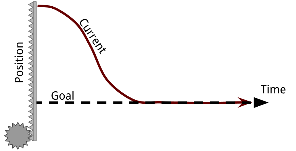
Choosing Values
Picking the right Kp and Kd values is important. To some extent, you can just do it by trial and error.
| Desired Result | Change |
|---|---|
| Get There Fast (low rise time) | Smaller Kp |
| Less Overshoot | Smaller Kp, Larger Kd |
| Less Vibration | Larger Kd |
It is no exagguration to say that there is a science to picking the right parameters, though. They can actually be precisely chosen by using math. Essentially, you need to be able to describe what you are controlling with an equation to make a transfer function, then find the characteristic equation. It's actually a lot easier than it sounds.
Using Node.js as a web server
Using Node.js as a web serverIntroduction
Node.js is JavaScript that can be run outside of a browser. It is often used to make a fast server for dynamic content.
Probably one of the biggest advantages to Node.js, aside from being one of the fastest and easiest to learn server environments, is that JavaScript is the lanugage used on browsers, allowing you to program both the server and client in the same language.
Example
First, download and install node.js
Then, start the example by usign the command:
nodejs server.js
This example starts by sending a static HTML form when you visit http://localhost:8080/. It looks like the image below:
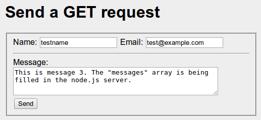
Clicking the submit button on the form sends a get request to http://localhost:8080/submit. It looks like the image below.
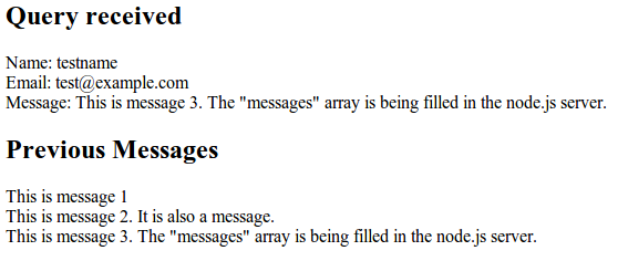
The interesting part of this script is the (url_parts.pathname == '/submit') condition. This is where the dynamic page generation happens. It starts by just regurgitating the information it was sent in the form. Note that the variable names of the url_parts.query.varname match up to the "name" attribute in each of the form elements. One of the most powerful features of node.js is that the program remains running between requests, unlike PHP. As a result, we can store variables which can retain their values as long as the process stays running. Storing any really important information this way is a bad idea, since a crash or shutdown would cause the data to disappear. A database can be used, such as MySQL. However, probably the most popular database for node.js servers is MongoDB, which uses JSON encoded data.
This form would also work by POST, if the form method were changed from GET to POST.
var http = require('http'); // these lines are somewhat similar to #include in C++
var util = require('util'); // except that the left hand side is an object/variable
var url = require('url');
var fs = require('fs');

// provide a "database"
messages = []

var server = http.createServer(function (req,res){
	 // parse the URL
	var url_parts = url.parse(req.url,true);

	// functions to serve static files
	function sendHTML(filepath) {
		// read the file asyncronously
		fs.readFile(filepath,function(error,contents){
			// once the file is loaded, this function runs
	    	console.log('Serving the html ' + filepath);
	    	res.end(contents); // end the request and send the file
	    });
	}
	function sendCSS(filepath) {
		// once the file is loaded, this function runs
		fs.readFile(filepath,function(error,contents){
	    	console.log('Serving the css ' + filepath);
	    	res.end(contents); // end the request and send the file
	    });
	}

	// serve the index page from a static file
	if( url_parts.pathname == '/' ) {
		sendHTML('./form.html');
	}
	// serve the CSS page from a static file
	else if ( url_parts.pathname == '/style.css') {
		sendCSS('./style.css')
	}
	// generate a dynamic page
	else if ( url_parts.pathname == '/submit' ) {
		var html = '<html><body>'; // begin the minimal html structure
		html += "<h2>Query received</h2>";
		html += "Name: " + url_parts.query.name;
		html += '<br />';
		html += "Email: " + url_parts.query.email;
		html += '<br />';
		html += "Message: " + url_parts.query.message;
		html += '<br />';

		html += '<h2>Previous Messages</h2>';
		messages.push(url_parts.query.message)

		// loop through the old messages
		for(m in messages) {
			html += messages[m];
			html += '<br />';
		}

		html += '</body></html>'; // end the minimal html structure

		res.end(html); // end the request and send the response HTML
	}
	// if the url was not recognized, 404
	else {
		res.writeHead(404) // put a header for not found
		// print the page and end the request
		res.end("<h1>404 - Path not recognized</h1>");
	}
 });

server.listen(8080);
util.log('Server listenning at localhost:8080');Python GUIs
Python GUIsPreface
Unless your robot is completely autonomous, you'll probably want a nice, centralized, and graphical way to control it. Really, you can use anything that can output to serial. Python is a really easy way to accomplish this with minimal programming thanks to its easy syntax and some well built libraries like pySerial, Tkinter, and Tornado.
Python provides a easy-to-use library called Tkinter that allows the user to make GUIs. This is a good way to get a nice windowed GUI on nearly most platforms (Windows, Mac, Linux). It requires minimal setup, and is relatively simple to use.
Another option for a Graphical User Interface is Tornado, which is a web server. With a web server, you can control your system from anywhere with an internet connection with anything with a web browser.
Basics of a Tkinter GUI
Basics of a Tkinter GUIIntroduction
It is often necessary to being to communicate with a robot while it is in use. This can be done simply through a remote control or more complexly through a GUI. The GUI can allow the robot to both send an receive information while a remote control will only be able to send to the robot. A simple way to make a GUI is through Python Tkinter. Using Tkinter along with Serial, the code will allow easy communication between the robot.
This tutorial will show how to use various parts of Tkinter and show how to make a GUI look good.
Importing Library
At the start of the code, it is necessary to import the necessary libraries:
from Tkinter import *
Importing the library in this fashion means that when the library is used, it does not have to be called every time. For communication between a robot, it will also be necessary to import the Serial library. To learn more about that, see Serial Commands.
Making a GUI
The first thing that must be done is to make the window that the GUI will be in. This is done with the following code:
root = Tk() #Makes the window
root.wm_title("Window Title") #Makes the title that will appear in the top left
root.config(background = "#FFFFFF") #sets background color to white

#put widgets here

root.mainloop() #start monitoring and updating the GUI. Nothing below here runs.
This gives a very basic window with a white background.
When making a Python GUI, there are several different widgets that can be used. Here, the following widgets will be discussed:
- Frame
- Label
- Entry
- Button
- Canvas
- Text
Frame
Frames are useful for the organization of a GUI. Frames get built into the grid of the window and then in turn each have a grid of their own. This means that nesting frames may be necessary if the GUI is going to look nice. To add a frame, the following code is needed:
leftFrame = Frame(root, width=200, height = 600)
leftFrame.grid(row=0, column=0, padx=10, pady=2)
The first line means that leftFrame will rest in root, which is the name that the window was given. The height and width are specified, but the frames re-size to what is put inside. The second line places the frame in the first grid spot open in root (0,0).
Label
A label allows either text or a picture to be placed. The text inside the label can be updated later if necessary. To add a label, the following code is needed:
firstLabel = Label(leftFrame, text="This is my first label")
firstLabel.grid(row=0, column=0, padx=10, pady=2)
This rests firstLabel in left frame with the following text in the first spot of leftFrame.
To get a picture in the label, the following code is used:
imageEx = PhotoImage(file = 'image.gif')
Label(leftFrame, image=imageEx).grid(row=0, column=0, padx=10, pady=2)
The image should be in the same folder that the Python file is in. Using PhotoImage, the image file should be a GIF or PGM.
Entry
The Entry widget is an input widget. It allows the user to type something that can then be read into the program. To use this widget, the following code is helpful:
userInput = Entry(leftFrame, width = 10) #the width refers to the number of characters
userInput.grid(row=0, column=0, padx=10, pady=2)

#get the text inside of userInput
userInput.get()
It may be necessary to get the inside of the entry when a button is pushed or when the user strikes enter.
Button
A button causes a specified action to occur. To use a button, the following is needed:
newButton = Button(leftFrame, text="Okay", command=btnClicked)
newButton.grid(row=0, column=0, padx=10, pady=2)
The command specified in the button is a function that will be called. The function holds the code that should fire when the button is pushed. This function should be above when the button is made.
Canvas
A canvas allows for various shapes and designs to be drawn onto it. These shapes will remain if more are added unless the shape's pixels are completely overwritten. To add a canvas, the following code is used:
newCanvas = Canvas(leftFrame, width=100, height=100, bg='white')
newCanvas.grid(row=0, column=0, padx=10, pady=2)
This gets the canvas. To draw on the canvas there are a large number of functions available, such as create_arc and create_line.
Text
A Text widget can either be written in or can be written to. To use it, the following is needed:
newText = Text(leftFrame, width=50, height=8, takefocus=0)
newText.grid(row=0, column=0, padx=10, pady=2)

#write to widget
newText.insert(0.0, "Text to insert") #0.0 is beginning of widget
The Text widget is good for creating logs since the data will remain and the user can look back at it.
GUI Example
It is often useful to map out what the GUI is going to look like before starting on it so that all the frames can be nested appropriately. A sketch should be made for the GUI so that it can be visualized, such as the following:
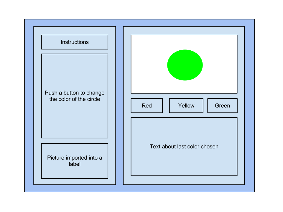
In the above example, only three frames would be necessary: a frame for the left side, a frame for the right side, and a frame surrounding the color buttons. Using this along with the code that was given previously, the following code can be made:
from Tkinter import *

root = Tk() #Makes the window
root.wm_title("Window Title") #Makes the title that will appear in the top left
root.config(background = "#FFFFFF")


def redCircle():
    circleCanvas.create_oval(20, 20, 80, 80, width=0, fill='red')
    colorLog.insert(0.0, "Red\n")

def yelCircle():
    circleCanvas.create_oval(20, 20, 80, 80, width=0, fill='yellow')
    colorLog.insert(0.0, "Yellow\n")

def grnCircle():
    circleCanvas.create_oval(20, 20, 80, 80, width=0, fill='green')
    colorLog.insert(0.0, "Green\n")


#Left Frame and its contents
leftFrame = Frame(root, width=200, height = 600)
leftFrame.grid(row=0, column=0, padx=10, pady=2)

Label(leftFrame, text="Instructions:").grid(row=0, column=0, padx=10, pady=2)

Instruct = Label(leftFrame, text="1\n2\n2\n3\n4\n5\n6\n7\n8\n9\n")
Instruct.grid(row=1, column=0, padx=10, pady=2)

try:
    imageEx = PhotoImage(file = 'image.gif')
    Label(leftFrame, image=imageEx).grid(row=2, column=0, padx=10, pady=2)
except:
    print("Image not found")

#Right Frame and its contents
rightFrame = Frame(root, width=200, height = 600)
rightFrame.grid(row=0, column=1, padx=10, pady=2)

circleCanvas = Canvas(rightFrame, width=100, height=100, bg='white')
circleCanvas.grid(row=0, column=0, padx=10, pady=2)

btnFrame = Frame(rightFrame, width=200, height = 200)
btnFrame.grid(row=1, column=0, padx=10, pady=2)

colorLog = Text(rightFrame, width = 30, height = 10, takefocus=0)
colorLog.grid(row=2, column=0, padx=10, pady=2)

redBtn = Button(btnFrame, text="Red", command=redCircle)
redBtn.grid(row=0, column=0, padx=10, pady=2)

yellowBtn = Button(btnFrame, text="Yellow", command=yelCircle)
yellowBtn.grid(row=0, column=1, padx=10, pady=2)

greenBtn = Button(btnFrame, text="Green", command=grnCircle)
greenBtn.grid(row=0, column=2, padx=10, pady=2)


root.mainloop() #start monitoring and updating the GUI
This code results in the following GUI:

This GUI completes all the functions it is intended to do, but does not do so in a very aesthetic fashion.
Making the GUI Attractive
Making the GUI AttractiveIntroduction
It is one thing to make a GUI and another to make a GUI that people will want to use. Despite the fact that the appearance of a GUI does not really affect how the program runs, it is always prudent to set up GUIs in a way that they could be presented professionally.
Although, this is really only important if the GUI runs properly. Making it function accordingly is always more important than its appearance.
Note: This will focus on improving the GUI example from the previous tutorial.
Making Frames the Same Height
When GUIs with multiple frames are built, it can be seen that each frame is its own unique size based on what is in each frame. Usually, this is a nuisance. Fortunately, there is an easy fix: Sticky.
This gets added when you put it in the grid:
leftFrame.grid(row=0, column=0, padx=10, pady=2, sticky=N+S)
The options for Sticky are: N, E, S, W.
Justification of Text in Labels
If there is only one line of text in the label, the text can be justified by using Anchor. However, sometimes it is necessary to have more than one line of text, such as the instructions label. In this case, it is necessary to use Wraplength to get the text wrapped. Unfortunately, this wants the wrap length in pixels rather than characters, so that can be a bit of a guessing game to get it right. If there is more than one line of text, it should also include Justify.
The code below shows an example of justification of multiple text to the left:
Instruct = Label(leftFrame, width=22, height=15, text=instructions, takefocus=0, wraplength=170, anchor=W, justify=LEFT)
The options for Anchor are: N, NE, E, SE, S, SW, W, NW, CENTER.
The options for Justification are: LEFT, RIGHT, CENTER.
Fonts
The main thing with fonts, is not to pick really obnoxious fonts that people are not going to want to look at. Simple fonts are better for the main GUI and if a stylized font is desired for only select portions, that is fine as long as the stylized font is not too crazy.
Fonts are added by using the following code:
Instruct = Label(leftframe, width=30, height=9, text=instructions, takefocus=0, wraplength=275, font=("MS Serif", 12), anchor=W, justify=LEFT, background=framebg)Background Colors
The initial background Python uses is white, which is a bit boring. To chose unique colors, it may be necessary to look up their RGB color codes. However, caution should be given when choosing colors. They should not be obnoxiously bright so that they attract away from the attention of the GUI itself. The colors should be neutral and minimally invasive.
This doesn't mean to only use beige or boring colors, but to choose gentler colors that people will not mind staring at.
The font color is added when the declaration was made, or can change later if needed:
leftFrame = Frame(root, width=200, height = 600, bg="#C8F9C4")
However, changing a frame does not change the color of the labels, so the background specification can be added to all of those as well.
Borders
Adding borders can be a nice touch to the various components in the GUI. To do this, the code should refer to the hightlight thickness, which determines the width of the border in pixels, and the highlight background, which refers to the backgrounds color.
An example of this is below:
leftFrame = Frame(root, width=200, height = 600, bg="#C8F9C4", highlightthickness=2, highlightbackground="#111")
Visual Arrangement
The arrangement of the GUI should be uncluttered and easy to read. Like options should be catergorized together, but seperated from other components. A lot of this is a matter of taste on who the end user is, so keep that in mind when designing GUIs.
GUI Example
Looking at the same GUI from the previous tutorial, here is the code to clean it up:
from Tkinter import *

root = Tk() #Makes the window
root.wm_title("Window Title") #Makes the title that will appear in the top left
root.config(bg = "#828481")


def redCircle():
    circleCanvas.create_oval(20, 20, 80, 80, width=0, fill='red')
    colorLog.insert(0.0, "Red\n")

def yelCircle():
    circleCanvas.create_oval(20, 20, 80, 80, width=0, fill='yellow')
    colorLog.insert(0.0, "Yellow\n")

def grnCircle():
    circleCanvas.create_oval(20, 20, 80, 80, width=0, fill='green')
    colorLog.insert(0.0, "Green\n")


#Left Frame and its contents
leftFrame = Frame(root, width=200, height = 600, bg="#C8F9C4", highlightthickness=2, highlightbackground="#111")
leftFrame.grid(row=0, column=0, padx=10, pady=2, sticky=N+S)

Inst = Label(leftFrame, text="Instructions:", anchor=W, bg="#C8F9C4")
Inst.grid(row=0, column=0, padx=10, pady=2, sticky=W)

instructions = "When one of the buttons on the is clicked, a circle\
 of the selected color appears in the canvas above. Red will result in a red circle. The color that is\
 selected will also appear in the output box below. This will track the various colors that\
 have been chosen in the past."
Instruct = Label(leftFrame, width=22, height=10, text=instructions, takefocus=0, wraplength=170, anchor=W, justify=LEFT, bg="#C8F9C4")
Instruct.grid(row=1, column=0, padx=10, pady=2)

imageEx = PhotoImage(file = 'image.gif')
Label(leftFrame, image=imageEx).grid(row=2, column=0, padx=10, pady=2)


#Right Frame and its contents
rightFrame = Frame(root, width=200, height = 600, bg="#C8F9C4", highlightthickness=2, highlightbackground="#111")
rightFrame.grid(row=0, column=1, padx=10, pady=2, sticky=N+S)

circleCanvas = Canvas(rightFrame, width=100, height=100, bg='white', highlightthickness=1, highlightbackground="#333")
circleCanvas.grid(row=0, column=0, padx=10, pady=2)

btnFrame = Frame(rightFrame, width=200, height = 200, bg="#C8F9C4")
btnFrame.grid(row=1, column=0, padx=10, pady=2)

colorLog = Text(rightFrame, width = 30, height = 10, takefocus=0, highlightthickness=1, highlightbackground="#333")
colorLog.grid(row=2, column=0, padx=10, pady=2)

redBtn = Button(btnFrame, text="Red", command=redCircle, bg="#EC6E6E")
redBtn.grid(row=0, column=0, padx=10, pady=2)

yellowBtn = Button(btnFrame, text="Yellow", command=yelCircle, bg="#ECE86E")
yellowBtn.grid(row=0, column=1, padx=10, pady=2)

greenBtn = Button(btnFrame, text="Green", command=grnCircle, bg="#6EEC77")
greenBtn.grid(row=0, column=2, padx=10, pady=2)


mainloop()
Here is the result:
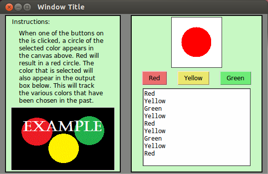
Python GUI broken into multiple files
Python GUI broken into multiple filesIntroduciton
TkInter GUIs can get extremely long very quick. Fortunately they can be split into multiple files - especially if you give them a class wrapper. The important thing is that you pass the relavent parent elements so more widgets can be inserted into the frame or window.
The below example shows how to take the previous python GUI example and break it into multiple files using Python modules.
Files
All of the below files must be in the same folder.
Main.py
Wow look how the main program is so short now.
from MyTkWindow import *

myWindow = MyTkWindow()
myWindow.start()
MyTkWindow.py
The main trunk of the code is handled in the the TkWindow file. It mainly creates the two panels.
from Tkinter import *
from MyLeftPanel import *
from MyRightPanel import *

class MyTkWindow:
	def __init__(self):

		self.root = Tk() #Makes the window
		self.root.wm_title("Window Title") #Makes the title that will appear in the top left
		self.root.config(background = "#FFFFFF")

		self.leftFrame = Frame(self.root, width=200, height = 600)
		self.leftFrame.grid(row=0, column=0, padx=10, pady=2)

		self.rightFrame = Frame(self.root, width=200, height = 300)
		self.rightFrame.grid(row=0, column=1, padx=10, pady=2)

		self.leftPanel = MyLeftPanel(self.root, self.leftFrame)
		self.rightPanel = MyRightPanel(self.root, self.rightFrame)

	def start(self):
		self.root.mainloop() #start monitoring and updating the GUI
So yeah, there is a lot of self now. It's not strictly necessary since you can actually just create local-scope variables because none of these are referenced again after they are created. However, it's always good to keep things avaialable that you might need later.
One really nice thing about the encapsulation gained by these class wrappers is that swapping things around becomes much easier. For example, you can swap the left and right panels easily by just changing to this:
		self.leftPanel = MyLeftPanel(self.root, self.rightFrame)
		self.rightPanel = MyRightPanel(self.root, self.leftFrame)
Without the encapsulation from classes, you would have to find everywhere the rightFrame variable was used and change it for leftFrame.
MyLeftPanel.py
This is pretty much just a class-ified version of the previous left panel.
from Tkinter import *

class MyLeftPanel:
	def __init__(self, root, frame):
		self.root = root
		self.frame = frame

		#Left Frame and its contents

		Label(self.frame, text="Instructions:").grid(row=0, column=0, padx=10, pady=2)


		self.instruct = Label(self.frame, text="1\n2\n2\n3\n4\n5\n6\n7\n8\n9\n")
		self.instruct.grid(row=1, column=0, padx=10, pady=2)

		try:
		    self.imageEx = PhotoImage(file = 'image.gif')
		    Label(self.frame, image=self.imageEx).grid(row=2, column=0, padx=10, pady=2)
		except:
		    print("Image not found")
MyRightPanel.py
The right panel class here takes advantage of another interesting Python feature: the lambda function. It is used here to pass an argument to a callback function. This lambda basically is just a wrapper function that injects the color string into the argument for makeCircle.
from Tkinter import *

class MyRightPanel:
	def __init__(self, root, frame):
		self.root = root
		self.frame = frame

		#Right Frame and its contents

		self.circleCanvas = Canvas(self.frame, width=100, height=100, bg='white')
		self.circleCanvas.grid(row=0, column=0, padx=10, pady=2)

		self.btnFrame = Frame(self.frame, width=200, height=10, borderwidth=1)
		self.btnFrame.grid(row=1, column=0, padx=10, pady=2)

		self.redBtn = Button(self.btnFrame, text="Red", command=lambda:self.makeCircle("red"))
		self.redBtn.grid(row=0, column=0, padx=10, pady=2)

		self.yellowBtn = Button(self.btnFrame, text="Yellow", command=lambda:self.makeCircle("yellow"))
		self.yellowBtn.grid(row=0, column=1, padx=10, pady=2)

		self.greenBtn = Button(self.btnFrame, text="Green", command=lambda:self.makeCircle("green") )
		self.greenBtn.grid(row=0, column=2, padx=10, pady=2)

		self.colorLog = Text(self.frame, width = 30, height = 10, takefocus=0)
		self.colorLog.grid(row=3, column=0, padx=10, pady=2)


	def makeCircle(self, color):
		self.circleCanvas.create_oval(20, 20, 80, 80, width=0, fill=color)
		self.colorLog.insert(0.0, color.capitalize() + "\n")
To compare, you can actually write the same thing without a lambda. What you would have to do is define a new function for each call. Like this:
        ...
                self.redBtn = Button(self.btnFrame, text="Red", command=self.makeRedCircle)
		self.redBtn.grid(row=0, column=0, padx=10, pady=2)

		self.yellowBtn = Button(self.btnFrame, text="Yellow", command=self.makeYellowCircle)
		self.yellowBtn.grid(row=0, column=1, padx=10, pady=2)

		self.greenBtn = Button(self.btnFrame, text="Green", command=self.makeGreenCircle )
		self.greenBtn.grid(row=0, column=2, padx=10, pady=2)

        def makeRedCircle(self):    # this line is replaced by lambda:
                self.makeCircle("red")

        def makeYellowCircle(self): # this line is replaced by lambda:
                self.makeCircle("yellow")

        def makeGreenCircle(self):  # this line is replaced by lambda:
                self.makeCircle("green")

        ...
As you can see, that gets pretty messy pretty quickly. It's a great way to create functions that are only used in one place like here, where we just need to inject an argument into the call of another function.
The repeated creation of the color buttons is also an ideal candidate for using a class to simplify code.
MyRightPanel.py (Class-ier)
Here, the repeated buttons are broken out into a class, which is duplicated. The advantage in this example is a little less apparent, but if you were to go back and want to make the buttons bigger or style them differently or even add a new one, it's a lot easier to maintain and keep the buttons the same.
The big key here is the callback function. The critical thing to notice to help visualze what is happening is that the function "makeCircle" is not called with () when the class is created. This means that the function is being passed, rather than the value returned by the function.
from Tkinter import *

class ColorButton:
	def __init__(self, frame, color, callback):
		self.frame = frame
		self.color = color   # the button's color is retained and accessible
		self.callback = callback

		self.button = Button(self.frame, text=self.color.capitalize(),
                                     command= lambda: self.callback(self.color) )

		#using pack eliminates the need to count grid spaces
                self.button.pack(side=LEFT)

class MyRightPanel:
	def __init__(self, root, frame):
		self.root = root
		self.frame = frame

		#Right Frame and its contents

		self.circleCanvas = Canvas(self.frame, width=100, height=100, bg='white')
		self.circleCanvas.grid(row=0, column=0, padx=10, pady=2)

		self.btnFrame = Frame(self.frame, width=200, height=10, borderwidth=1)
		self.btnFrame.grid(row=1, column=0, padx=10, pady=2)

                # significantly simplified button creation
		self.redBtn = ColorButton(self.btnFrame, "red", self.makeCircle)
		self.yellowBtn = ColorButton(self.btnFrame, "yellow", self.makeCircle)
		self.greenBtn = ColorButton(self.btnFrame, "green", self.makeCircle)

		self.colorLog = Text(self.frame, width = 30, height = 10, takefocus=0)
		self.colorLog.grid(row=3, column=0, padx=10, pady=2)

	def makeCircle(self, color):
		self.circleCanvas.create_oval(20, 20, 80, 80, width=0, fill=color)
self.colorLog.insert(0.0, color.capitalize() + "\n")Python Web UI with Tornado
Python Web UI with TornadoIntroduction
So, you want a GUI for your robot. Sure, you could make a nice GUI in Python with Tkinter, but there are some really good reasons to try it as a website instead:
- A web GUI can be accessed from almost any location
- A well-designed web GUI can be used on almost any device like a tablet or a phone
- HTML, CSS, and Javascript are well documented, powerful, and very flexible
- HTML can be easily made to look very nice
There are some drawbacks to implementing your GUI as a website though:
- It is only able to start communication one-way (browser to server, server responds)
- Great for buttons and other input
- Requres continuous polling or a commet to get data to be pushed to the browser
- It adds another "layer" of complexity to your code
- Several different languages (C++ on Arduino, Python Server, and HTML+CSS+Javascript in browser)
- The server has to relay information from the browser to the robot
Installing Python Tornado
I used the Tornado web server for my projects. It is better than just using CGI, since the environment is always loaded while the server is running instead of loading it every time a request is made. CGI would be problematic then, since serial.begin would be run every time a request was made, which simply wouldn't work since the Arduino would also restart all the time.
On Ubuntu, the installation is as easy as:
sudo apt-get install python-tornado python-serial
Using Tornado with the Serial Library
So one of the challenges with this is that reading serial input in python is usually blocking, so the webserver becomes unresponsive to browsers' requests while waiting for serial input.
#! /usr/bin/python2.7
import os
import json
import tornado.ioloop
import tornado.web
from serial import *


tornadoPort = 8888
cwd = os.getcwd() # used by static file server


# Make a Serial object
serialPort = '/dev/ttyACM0'
serialBaud = 9600
ser = Serial( serialPort, serialBaud, timeout=0, writeTimeout=0 )


# gets serial input in a non-blocking way
serialPending = ''
def checkSerial():
    try:
        s = ser.read( ser.inWaiting() )
    except:
        print("Error reading from %s " % serialPort )
        return

    if len(s):
        serialPending += s
        paseSerial()


#called whenever there is new input to check
serialHistory = ''
mostRecentLine = ''
def parseSerial():
    split = serialPending.split("\r\n")
    if len( split ) > 1:
        for line in split[0:-1]:
            print( line )

            #do some stuff with the line, if necessary
            #example:
            mostRecentLine = line
            # in this example, status will show the most recent line

            serialHistory += line

        pending = split[-1]


# send the index file
class IndexHandler(tornado.web.RequestHandler):
    def get(self, url = '/'):
        self.render('index.html')
    def post(self, url ='/'):
        self.render('index.html')


# handle commands sent from the web browser
class CommandHandler(tornado.web.RequestHandler):
    #both GET and POST requests have the same responses
    def get(self, url = '/'):
        print "get"
        self.handleRequest()

    def post(self, url = '/'):
        print 'post'
        self.handleRequest()

    # handle both GET and POST requests with the same function
    def handleRequest( self ):
        # is op to decide what kind of command is being sent
        op = self.get_argument('op',None)

        #received a "checkup" operation command from the browser:
        if op == "checkup":
            #make a dictionary
            status = {"server": True, "mostRecentSerial": mostRecentLine }
            #turn it to JSON and send it to the browser
            self.write( json.dumps(status) )

        #operation was not one of the ones that we know how to handle
        else:
            print op
            print self.request
            raise tornado.web.HTTPError(404, "Missing argument 'op' or not recognized")


# adds event handlers for commands and file requests
application = tornado.web.Application([
    #all commands are sent to http://*:port/com
    #each command is differentiated by the "op" (operation) JSON parameter
    (r"/(com.*)", CommandHandler ),
    (r"/", IndexHandler),
    (r"/(index\.html)", tornado.web.StaticFileHandler,{"path": cwd}),
    (r"/(.*\.png)", tornado.web.StaticFileHandler,{"path": cwd }),
    (r"/(.*\.jpg)", tornado.web.StaticFileHandler,{"path": cwd }),
    (r"/(.*\.js)", tornado.web.StaticFileHandler,{"path": cwd }),
    (r"/(.*\.css)", tornado.web.StaticFileHandler,{"path": cwd }),
])


if __name__ == "__main__":

    #tell tornado to run checkSerial every 10ms
    serial_loop = tornado.ioloop.PeriodicCallback(checkSerial, 10)
    serial_loop.start()

    #start tornado
    application.listen(tornadoPort)
    print("Starting server on port number %i..." % tornadoPort )
    print("Open at http://127.0.0.1:%i/index.html" % tornadoPort )
    tornado.ioloop.IOLoop.instance().start()
Setting up the Browser
To make it easy to send requests to the server, it's really a good idea to use jquery, and the easiest way to use jquery is to use the Google API for it. To add jquery to the webpage, just add this script:
<script src="//ajax.googleapis.com/ajax/libs/jquery/1.9.0/jquery.min.js"></script>
So to start, we'll just have a simple webpage that has a div. When the div is clicked, jquery will ask the status of the tornado webserver.
<!DOCTYPE html>
<html>
<head>
<title>Python Tornado Test Page</title>
<script src="http://ajax.googleapis.com/ajax/libs/jquery/1.8.2/jquery.min.js"></script>
<script>
function serverResponded( data ) {
    /*
    log the event data, so you can see what's going on.
    Shows up in the console on your browser. (Chrome: Tools > Developer Tools > Console)
    */
    console.log( data );

    // check the server status, and report it on the screen
    if ( data.server === true ) {
        $('#status .value').html("OK");
    }
    else {
        $('#status .value').html("NOT OK");
    }

    // add the last serial to the div on the screen
    $('#serial .value').html( data.mostRecentSerial );
}

$(document).ready( function() {
    /* handle the click event on the clickme */
    $('#clickme').click( function() {
        params = { op: "checkup" };
        $.getJSON( 'http://localhost:8888/com' , params, serverResponded );
    });
});
</script>
</head>
<body>
    <div id="clickme" style="cursor: pointer;">CLICK ME</div>

    <div id="status">
        Server Status: <span class="value">?</span>
    </div>

    <div id="serial">
        Last Serial Input: <span class="value"></span>
    </div>
</body>3D SVG Graph
3D SVG GraphIntroduction
An SVG is a type of graphic that is defined by shapes and math instead of discrete pixels. So, it is scales nicely, but can't make photo-realistic images. An (currently) SVG is two dimensional. That does not mean, though, that we cannot represent 3D information in this 2D space. After all, it is shown in 2D anyway. To accomplish this, we will build our own 3D rotation matrices, and a 3D to 2D projection matrix. The 3D points can be multiplied by both of these matrices to make it appear 3D, albeit somewhat flat due to the orthographic projection.
Interactive Graph Demo
This SVG grapher was made so that a user easily visualize and control the end manipulator of a robotic arm in 3D through a web browser. It may be viewed on this page on the NIU College of Engineering and Engeering Technology website, but the arm is usually left off for safety.
Hold left click and drag to move point.
Hold middle click and drag to rotate.
Usage
Although the implementation starts to get somewhat complicated, the usage is actually somewhat straightforward. Get the attached javascript file, and make an html file that contains this:
<script src="http://ajax.googleapis.com/ajax/libs/jquery/1.8.2/jquery.min.js"></script>
<script src="3dgraph.js"></script>

<svg xmlns="http://www.w3.org/2000/svg" version="1.1" height="320" width="352" id="3d-graph" style="height: 320px; width:342px; margin: 0 auto; padding: 5px;" >
    <!-- neg axis -->
    <line x1="100" y1="250" x2="400" y2="250" id="neg-axis-x" style="stroke:rgba(250,200,200,0.5);stroke-width:2"/>
    <line x1="100" y1="250" x2="100" y2="0"   id="neg-axis-y" style="stroke:rgba(200,250,200,0.5);stroke-width:2"/>
    <line x1="100" y1="250" x2="0" y2="400"   id="neg-axis-z" style="stroke:rgba(200,200,250,0.5);stroke-width:2"/>
    <!-- axis -->
    <line x1="100" y1="250" x2="400" y2="250" id="axis-x" style="stroke:rgb(200,0,0);stroke-width:2"/>
    <line x1="100" y1="250" x2="100" y2="0"   id="axis-y" style="stroke:rgb(0,200,0);stroke-width:2"/>
    <line x1="100" y1="250" x2="0" y2="400"   id="axis-z" style="stroke:rgb(0,0,200);stroke-width:2"/>
</svg>
Interfacing
The coordinates of the point above are stored in the variables tx, ty, and tz. If you just wish to read it, just read the variables. If you modify them, you have to update the display with mainDot.changePoint()
A point is simply a vector. A dot is the point plus the graphical representation. A line is two points and a graphical connection between them.
How it Works
This implementation uses the jQuery library, which is much less useful than usual since jQuery can only create HTML DOM objects and not SVG DOM objects as required in this usage. It is still useful for it's event bindings and some search features.
There is a point class with an x, y, and z. Points are used to in the graphical classes Dot and Line, where line has two points for a start and an end. Points are multiplied by rotation and projection matrices to turn their 3 dimensions into 2 dimensions. The rotation matrix angles are modified by mouse movement during a click event. When the rotation matrix is changed, the points must be multiplied with the new matrix and the result must be updated on the SVG.
In this specific usage, there were 7 points used for the axes. A zero point and points at the maximum and minimum (positive and negative) for each direction. There is a dot at the point you want to visualize in the 3D space, as well as 3 guide lines to help with perspective. The guide lines are entirely necessary. It would also be possible to plot a curved line by using many Line classes or even making your own class that uses the SVG path tag to generate a smooth curve. Another possible feature might be to put a Dot class at a point on the lone closest to the mouse and showing the x,y, and z coordinates.
Tkinter with Serial
Tkinter with SerialIntroduction
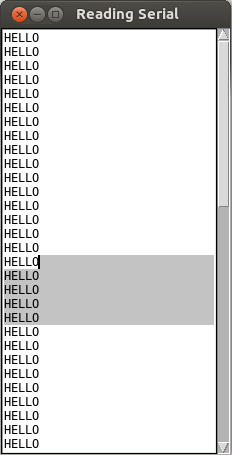 To use Python as a graphical interface for an Arduino powered robot, programmatically read the USB with the pySerial library. However, waiting for input from pySerial's Serial object is blocking, which means that it will prevent your GUI from being responsive. The process cannot update buttons or react to input because it is busy waiting for the serial to say something.
The first key is to use the root.after(milliseconds) method to run a non-blocking version of read in the tkinter main loop. Keep in mind that when TkInter gets to the root.mainloop() method, it is running its own while loop. It needs the things in there to run every now and then in order to make the interface respond to interactions. If you are running your own infinite loop anywhere in the code, the GUI will freeze up. Alternatively, you could write your own infinite loop, and call root.update() yourself occasionally. Both methods achieve basically the same goal of updating the GUI.
However, the real issue is making sure that reading from serial is non-blocking. Normally, the Serial.read() and Serial.readline() will hold up the whole program until it has enough information to give. For example, a Serial.readline() won't print anything until there is a whole line to return, which in some cases might be never! Even using the after() and update() methods will still not allow the UI to be updated in this case, since the function never ends. This problem can be avoided with the timeout=0 option when enitializing the Serial object, which will cause it to return nothing unless something is already waiting in the Serial object's buffer.
Code
from serial import *
from Tkinter import *

serialPort = "/dev/ttyACM0"
baudRate = 9600
ser = Serial(serialPort , baudRate, timeout=0, writeTimeout=0) #ensure non-blocking

#make a TkInter Window
root = Tk()
root.wm_title("Reading Serial")

# make a scrollbar
scrollbar = Scrollbar(root)
scrollbar.pack(side=RIGHT, fill=Y)

# make a text box to put the serial output
log = Text ( root, width=30, height=30, takefocus=0)
log.pack()

# attach text box to scrollbar
log.config(yscrollcommand=scrollbar.set)
scrollbar.config(command=log.yview)

#make our own buffer
#useful for parsing commands
#Serial.readline seems unreliable at times too
serBuffer = ""

def readSerial():
    while True:
        c = ser.read() # attempt to read a character from Serial

        #was anything read?
        if len(c) == 0:
            break

        # get the buffer from outside of this function
        global serBuffer

        # check if character is a delimeter
        if c == '\r':
            c = '' # don't want returns. chuck it

        if c == '\n':
            serBuffer += "\n" # add the newline to the buffer

            #add the line to the TOP of the log
            log.insert('0.0', serBuffer)
            serBuffer = "" # empty the buffer
        else:
            serBuffer += c # add to the buffer

    root.after(10, readSerial) # check serial again soon


# after initializing serial, an arduino may need a bit of time to reset
root.after(100, readSerial)

root.mainloop()
Projects
ProjectsPreface
All this knowledge is great, but you really learn best by practicing what you learn. If you'd like some ideas for some fun projects to hone your skills on, we've been looking for the same thing. These are some projects that we have liked doing. A lot of them are going to have to do with Arduino - it's a great platform, we like using it, and you should too.
Arduino Sketcher
Arduino SketcherIntroduction
I had gotten a joystick a while ago and wanted to do something different and interesting with it. After coming up with and discarding a bunch of other ideas, I came up with the Arduino Sketcher. The ideas was to make something similar to an Etch-a-Sketch but uses the joystick instead of two dials. The computer would serve as the sketching pad while to Arduino relayed all the commands sent by the user. This project uses both Arduino and Python and turned out to be fairly simple to implement.
Schematic
Below is the schematic of the Arduino Sketcher.

The sketcher allows the user to click on various parts of the canvas to determine where the lines start out. This allows for disconnected lines. It uses the joystick to determine where to draw the line and how quickly. The more the user shifts the joystick, the faster it draws lines. When the user holds the joystick down, the button triggers and a circle will be drawn on the canvas. The longer the button is held down, the larger the circle is. The buttons next to the joystick allow the user to select various colors indicated by the wire. There are buttons available that are colored and can be used to indicate color.
Code
Arduino Code
Below is the code on the Arduino side. The Arduino is mostly used to translate the controller and send commands to the Python side.
/****************************
Controller for Sketcher

Jennifer Case
13/06/2013
****************************/

//Declare pins
int redPin = 7;
int yelPin = 6;
int grnPin = 5;
int bluPin = 4;
int blkPin = 3;
int verPin = A0;
int horPin = A1;
int circlePin = 8;

int lastColor = 4;
long previousMillis = 0;
long interval = 200;
float numClicks = 0;

void setup() {
  Serial.begin(38400);

  pinMode(redPin, INPUT);
  pinMode(yelPin, INPUT);
  pinMode(grnPin, INPUT);
  pinMode(bluPin, INPUT);
  pinMode(blkPin, INPUT);
  pinMode(circlePin, INPUT);
  digitalWrite(circlePin, HIGH);
}

void loop() {
  //read values from color buttons
  int redBtn = digitalRead(redPin);
  int yelBtn = digitalRead(yelPin);
  int grnBtn = digitalRead(grnPin);
  int bluBtn = digitalRead(bluPin);
  int blkBtn = digitalRead(blkPin);
  //read and normalize values from the potentiameters
  float verPos = (analogRead(verPin)-504.0)/504.0;
  float horPos = (496.0-analogRead(horPin))/496.0;
  //read value of button
  boolean circleBtn = digitalRead(circlePin);

  //if either normalized value from the joystick is
  //essentially zero, make it equal zero
  if (verPos < 0.01 && verPos > -0.01) {verPos = 0;}
  if (horPos < 0.01 && horPos > -0.01) {horPos = 0;}

  unsigned long currentMillis = millis();
  char charBuf[5];

  //if enough time has passed and either potentiameter is not zero,
  //print out commands for both axes
  if(currentMillis - previousMillis > interval && (verPos != 0 || horPos != 0)) {
    Serial.print("X,");
    dtostrf(verPos, 4, 2, charBuf); //turn float to string
    Serial.println(charBuf);
    Serial.print("Y,");
    dtostrf(horPos, 4, 2, charBuf); //turn float to string
    Serial.println(charBuf);

    previousMillis = currentMillis; //reset the interval
  }

  //determine color and print it to sketcher if it was not the last color
  if (redBtn && lastColor != 0) {
    Serial.println("C,R"); //print command
    lastColor = 0;
  }
  else if (yelBtn && lastColor != 1) {
    Serial.println("C,Y"); //print command
    lastColor = 1;
  }
  else if (grnBtn && lastColor != 2) {
    Serial.println("C,G"); //print command
    lastColor = 2;
  }
  else if (bluBtn && lastColor != 3) {
    Serial.println("C,B"); //print command
    lastColor = 3;
  }
  else if (blkBtn && lastColor != 4) {
    Serial.println("C,K"); //print command
    lastColor = 4;
  }

  //while button on joystick is clicked,
  while (!circleBtn) {
    numClicks++; //increase counter
    circleBtn = digitalRead(circlePin); //read the button again
  }

  //if numClicks is more than zero,
  if (numClicks > 0) {
    Serial.print("O,"); //start printing command
    numClicks = numClicks/20000.0; //normalize the numClicks
    dtostrf(numClicks, 4, 2, charBuf); //int to string
    Serial.println(charBuf); //print the rest of the command
    numClicks = 0; //reset numClicks
  }
}
Python Code
Below is the Python code. It just translates the commands from the Arduino side and draws the appropriate lines on the canvas. It should be noted that this was coded for Python 3.
#! /usr/bin/python

from serial import *
from tkinter import *
import time


#Serial
ser = Serial("COM9",38400,timeout=0,writeTimeout=0)
time.sleep(1)

#initialize positions
xPos = 500
yPos = 300

#function for making a circle
def drawcircle(canv,x,y,rad,color):
    canv.create_oval(x-rad,y-rad,x+rad,y+rad,width=0,fill=color)

#function for mouse click
def goToClick(event):
    global xPos
    global yPos
    xPos = event.x
    yPos = event.y

#Main window
root = Tk() #Tk is a function that makes a class
root.wm_title("Canvas Sketch")
root.config(bg="#8D8A8A", bd="0")

#make the sketcher canvas
sketcher = Canvas(root, width=1000, height=600, bg='white')
sketcher.grid(row=0, column=0)
sketcher.bind('<Button-1>', goToClick)

#log = Text(root, width=50, height=8, takefocus=0)
#log.grid(row=1, column=0, padx=2, pady=2)

#initializations
color = 'black'
verPos = 0
horPos = 0

def runLoop(event=0):
    ln = ser.readline() #get command
    lineStr = ln.decode(encoding='UTF-8')
    #log.insert('0.0',lineStr)

    #print(lineStr)
    #initializations
    Xline = 0
    Yline = 0
    circline = 0
    newLine = 0

    #other neccessary variables
    global verPos
    global horPos
    global xPos
    global yPos
    global color

    #determine selected color
    if "C" in lineStr:
        for line in lineStr.split(','):
            if "R" in line:
                color = 'red'
            if "Y" in line:
                color = 'yellow'
            if "G" in line:
                color = 'green'
            if "B" in line:
                color = 'blue'
            if "K" in line:
                color = 'black'

    #get X value
    elif "X" in lineStr:
        if len(lineStr) > 6: #make sure length is appropriate
            for line in lineStr.split(','):
                if Xline == 1:
                    #take value from lineStr
                    verPos = float(line.strip("\n \r"))*-1 #fix direction
                    #print(verPos)
                    Xline = 0
                elif Xline == 0:
                    Xline = 1

    #get Y value
    elif "Y" in lineStr:
        for line in lineStr.split(','):
            if Yline == 1:
                #take value from lineStr
                horPos = float(line.strip("\n \r"))
                #print(horPos)
                Yline = 0
                newLine = 1 #indicates that a line is ready to be drawn
            elif Yline == 0:
                Yline = 1

    #draw circle
    elif "O" in lineStr:
        if len(lineStr) > 4: #checks length
            for line in lineStr.split(','):
                if circline == 1:
                    #gets value
                    circDiam = float(line.strip("\n \r"))
                    #draw circle
                    drawcircle(sketcher,xPos,yPos,5*circDiam,color)
                    circline = 0
                elif circline == 0:
                    circline = 1

    if newLine == 1:
        newY = yPos+5*verPos #finds new end position
        newX = xPos+5*horPos #finds new end position
        sketcher.create_line(xPos, yPos, newX, newY, fill=color, width = 2)
        xPos = newX #adjusts end position
        yPos = newY #adjusts end position

    root.after(10, runLoop)

runLoop()

root.mainloop()
Example of Sketches
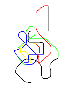
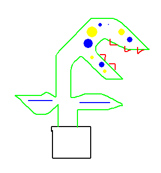
Computer Power Supply
Computer Power SupplyIntroduction
A lot of us have an old desktop computer we don't want anymore and it's good to re-use components. You'll find in each standard sized desktop, an ATX power supply. It's a standardized form factor for AC-to-DC power conversion with +3, +5, +12, and sometimes -5 and -12 VDC rails. If you look on the side, there is a sticker that will say what power it is rated to output.
Most power supplies are rated for usage in the range of 300 Watts to 600 Watts. High end ones go from 700 to 1200 Watts. That's not "toy" power. It can be dangerous and these things don't seem to have any fuses or anything in them. I melted a +5VDC wire for a few seconds when it accidentally contacted a ground. You could definitely start a fire with this and maybe hurt yourself. That being said, it is nice to have a nearly unlimited and somewhat well regulated power supply for no cost. You can get them new for about 20$ too, which seems like a good deal due to the variety of standardized voltages available.
It is not entirely straightforward to use these. They don't just turn on when they get power and there is no button for it. It is designed to be managed by an ATX compatible motherboard on computer. Basically, you need to short a specific pin to ground with a specific resistance (or use a potentiometer, like I did).
Completed Project Gallery:
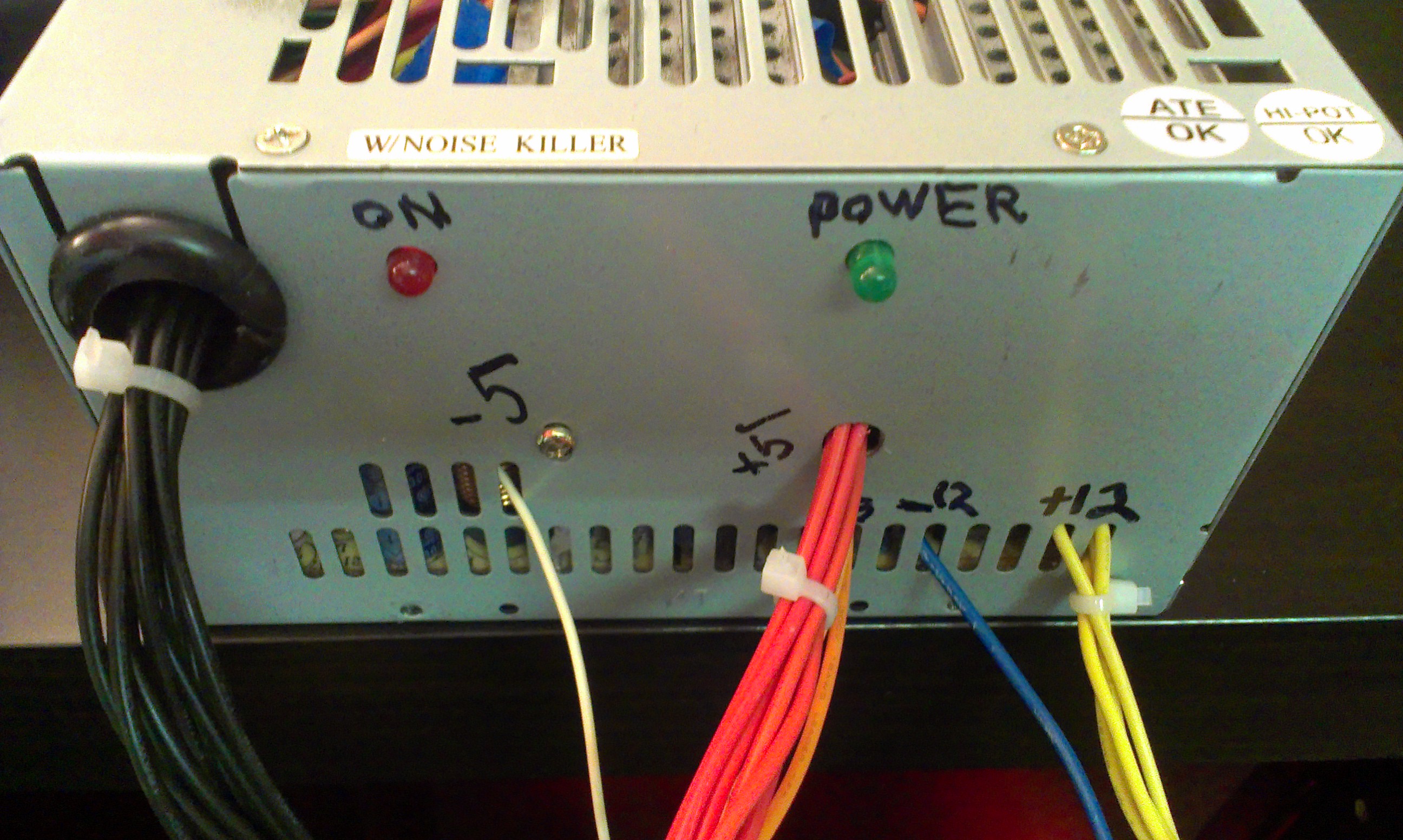
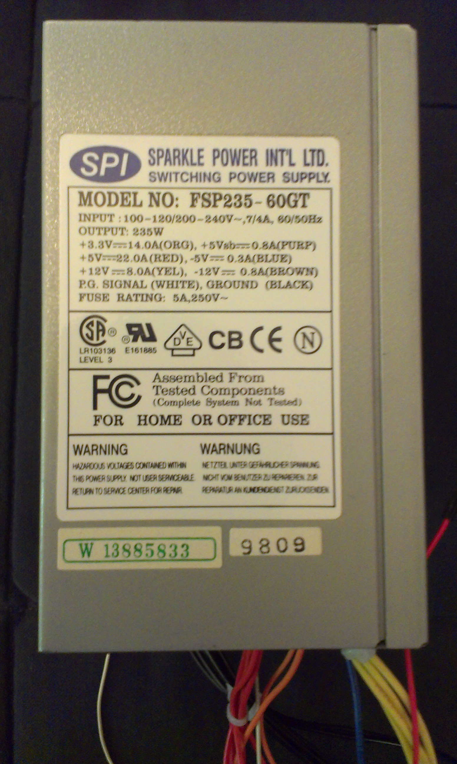
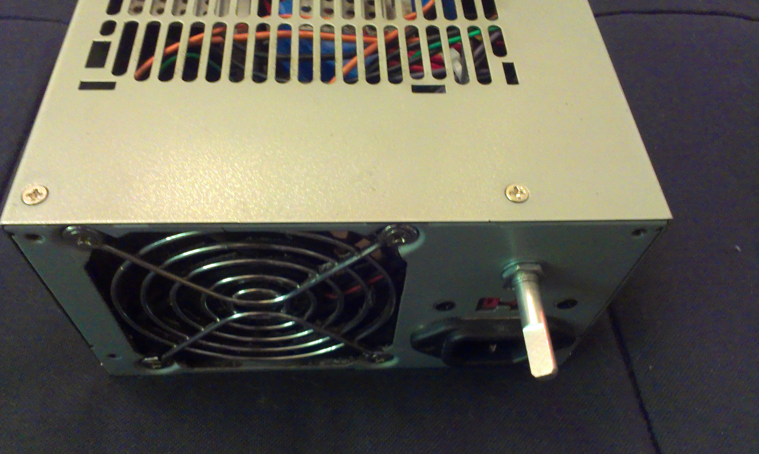
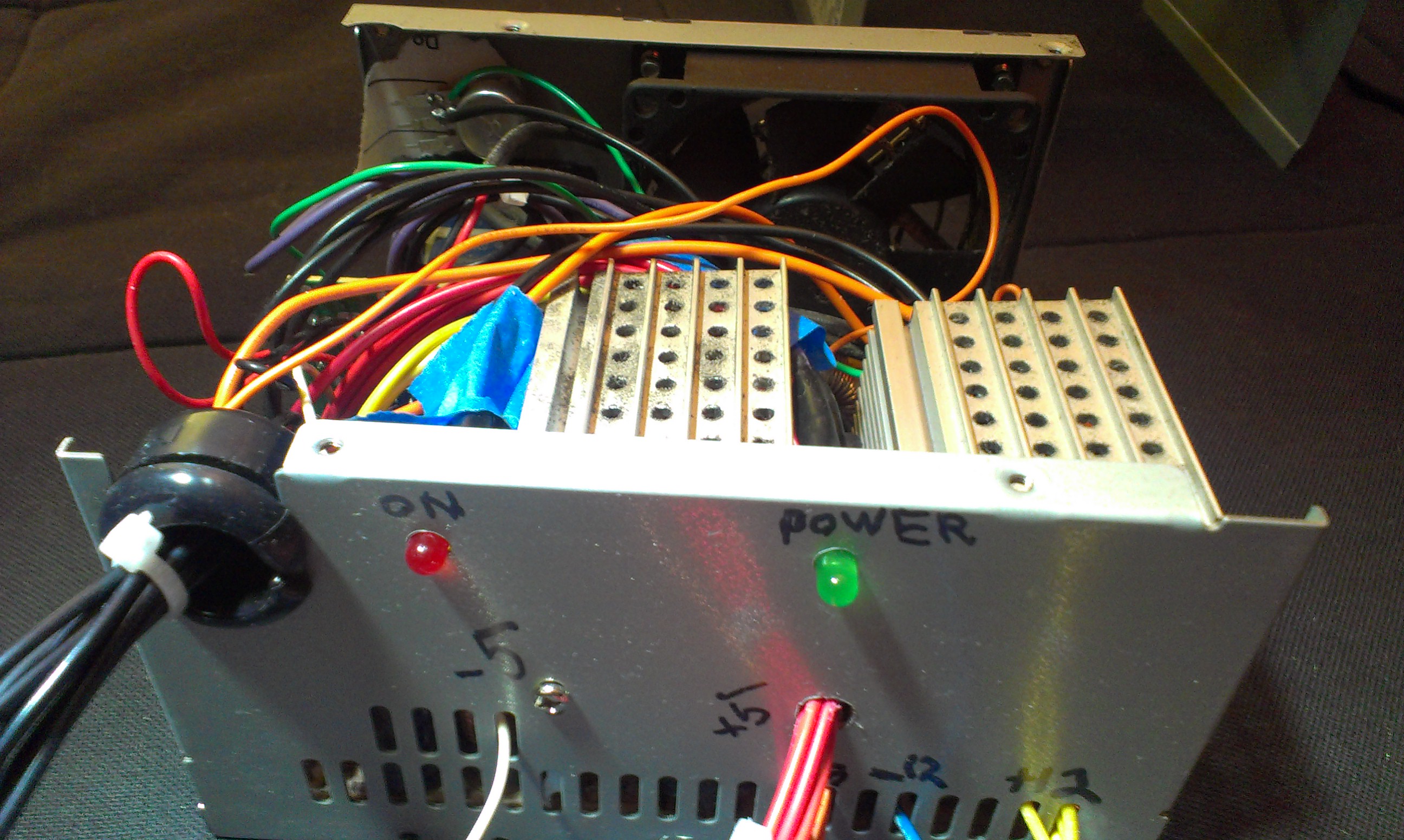
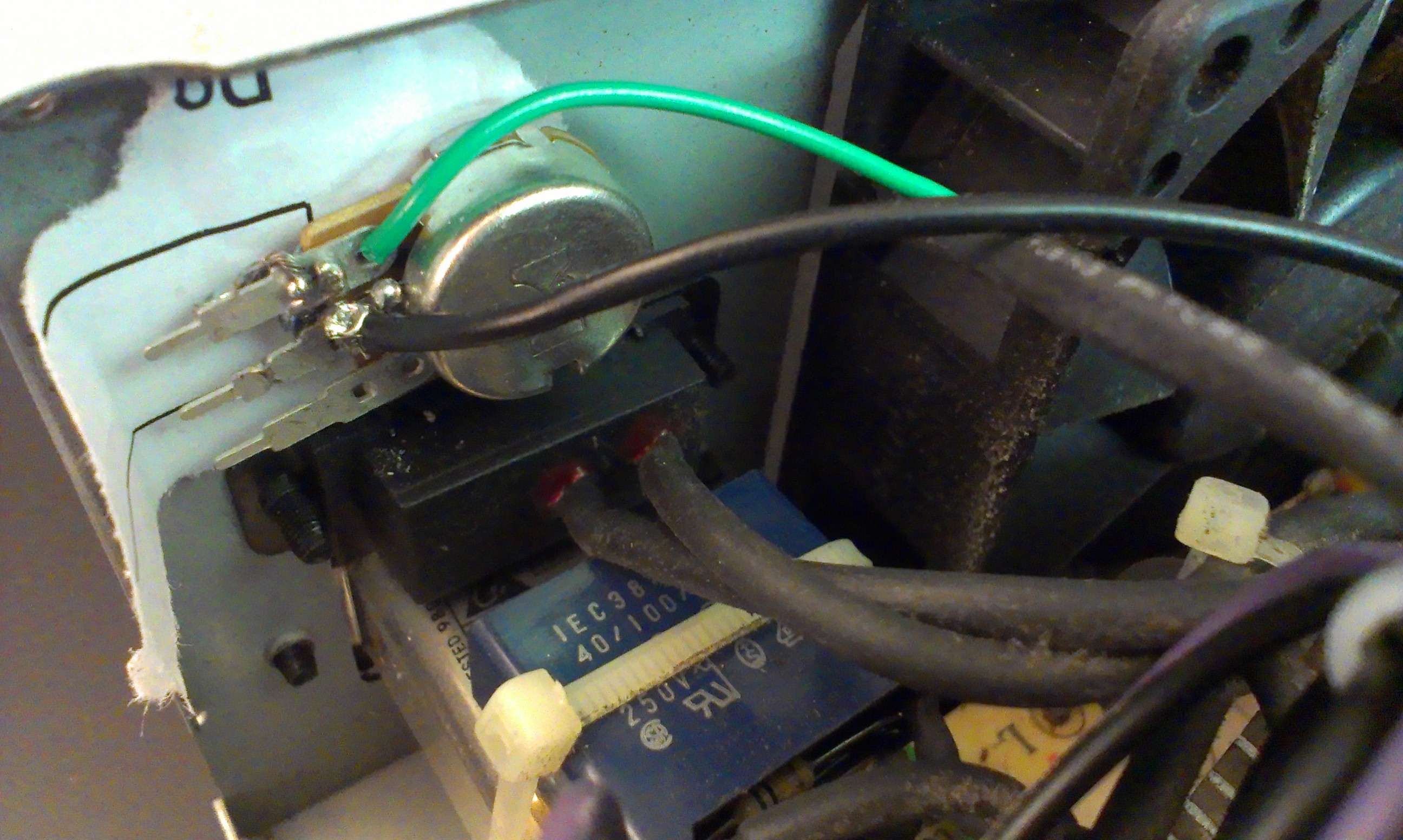
Parts
- A computer (ATX) power supply
- A potentiometer OR an appropriate resistor and toggle button
- A green LED for the power indicator
- A red LED to show that the supply is on
- Two resistors (220-1000 Ohm) for the LEDs
- Binding Posts (optional)
- Voltage Regulators (optional)
Planning
If you want to add a button or potentiometer to turn it on, you'll need to cut a hole for it in the back. Potentiometers and certain buttons work nice because all you need to do is drill a hole of the right size and you can easily attach it with a nut and lock washer.
If you want some indicator LEDs, you'll have to drill holes for those too - probably on the front somewhere. You will need to open up the power supply and look carefully for a place to drill that won't damage the components.
Wiring
The Standard Connectors
| Color | Signal | Pin | Pin | Signal | Color |
|---|---|---|---|---|---|
| Orange | +3.3 V | 1 | 13 | +3.3 V | Orange |
| sense | Brown | ||||
| Orange | +3.3 V | 2 | 14 | −12 V | Blue |
| Black | Ground | 3 | 15 | Ground | Black |
| Red | +5 V | 4 | 16 | Power on | Green |
| Black | Ground | 5 | 17 | Ground | Black |
| Red | +5 V | 6 | 18 | Ground | Black |
| Black | Ground | 7 | 19 | Ground | Black |
| Grey | Power good | 8 | 20 | Reserved | N/C |
| Purple | +5 V standby | 9 | 21 | +5 V | Red |
| Yellow | +12 V | 10 | 22 | +5 V | Red |
The standard connectors, ATX and Molex, will both be removed and reorganized into something more like a lab power supply than one that can only power a desktop computer.
The ATX connector has 20 pins and a clip on one side: 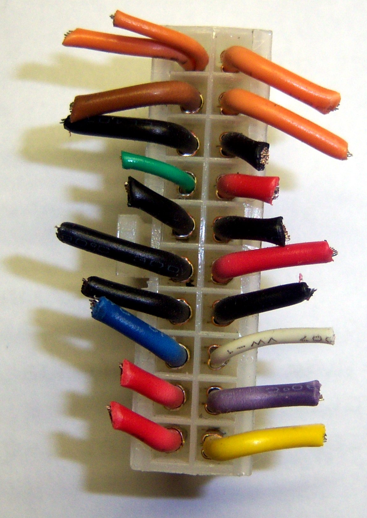
Note that the pins in the photo are flipped horizontally from the pins according to wikipedia. Also, some of those pins don't match up. The colors seem to be accurate though. You may wish to look for a version of the ATX table that matches the configuration of your power supply.
If you have that smaller orange/brown wire on Pin 13, just cut it off completely. It is not very useful and just confuses things. On mine, it was orange, so I kept thinking it was supposed to be 3.3V.
The ON Switch
Turning the power supply on isn't entirely straightforward. It won't just turn on when you plug it in.
You can touch the green wire, which is the "Power On" (aka PS_ON) to a Ground (black wire). However, it needs a specific resistance. Otherwise it will just turn on for a fraction of a second and then turn back off. Rather than just trying out what resistance it needed, I used a potentiometer. If you want to use a button, I'd still use the potentiometer to experimentally determine the range of values you can use for the resistance.
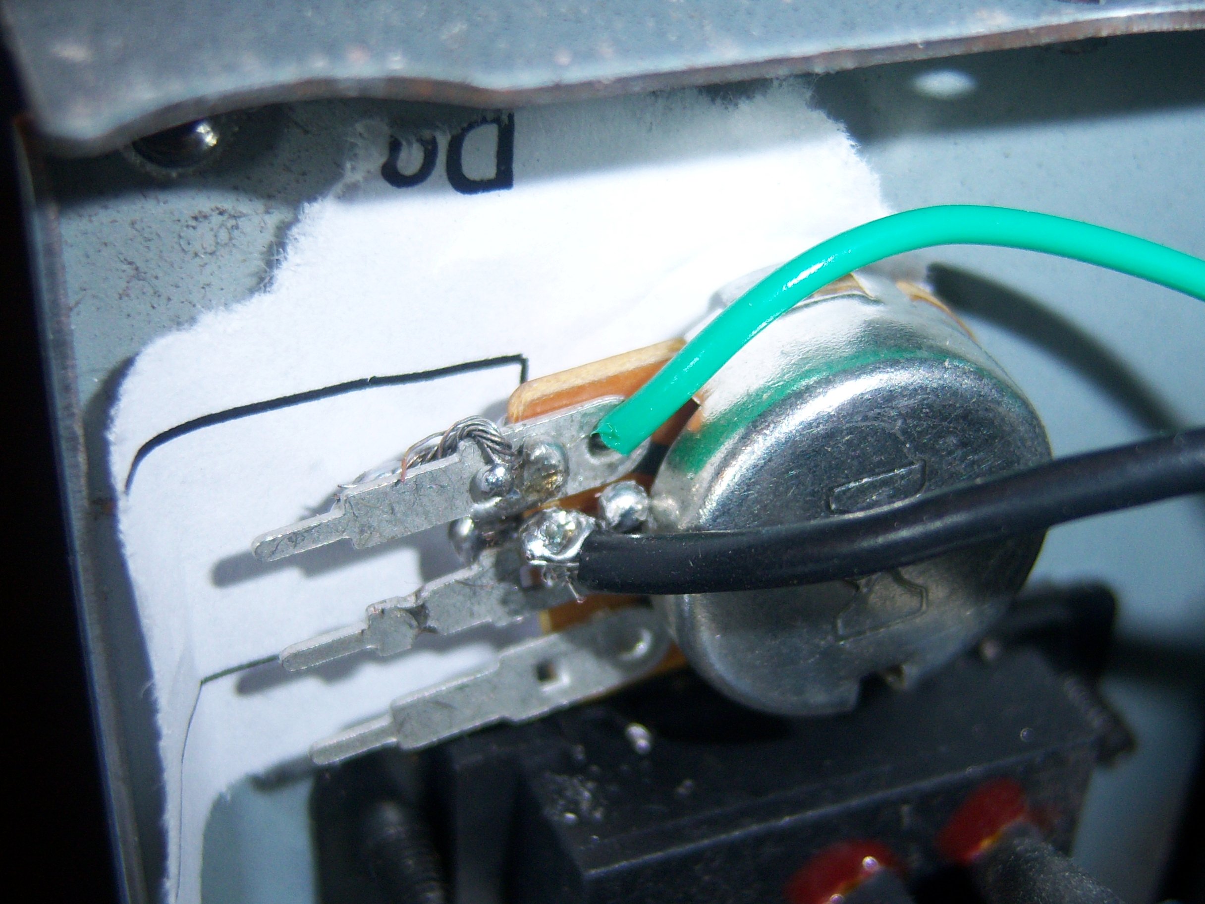
Be very sure when testing how to turn it on that you don't shock yourself, or have any of the leads touching each other. At this point, you should only really need to have cut the green wire out of the 20 pin ATX molex connector and any of the black grounds.
Clearly, I did not do a great job of soldering this thing. It was actually my first time ever soldering, and it works. Minor victory.
The green wire can go on either end of the potentiometer (pot) - all it will change is which end has higher resisistance. The ground goes on the middle pin. I would guess you could probably even flip these wires and it would still work.
If you want to use a button, try turning on the power supply with the potentiometer a few times. Get a multimeter / voltmeter and see what the resistance is of the potentiometer between the two pins you are using. That will be the resistance you should target between your button.
Power LEDs
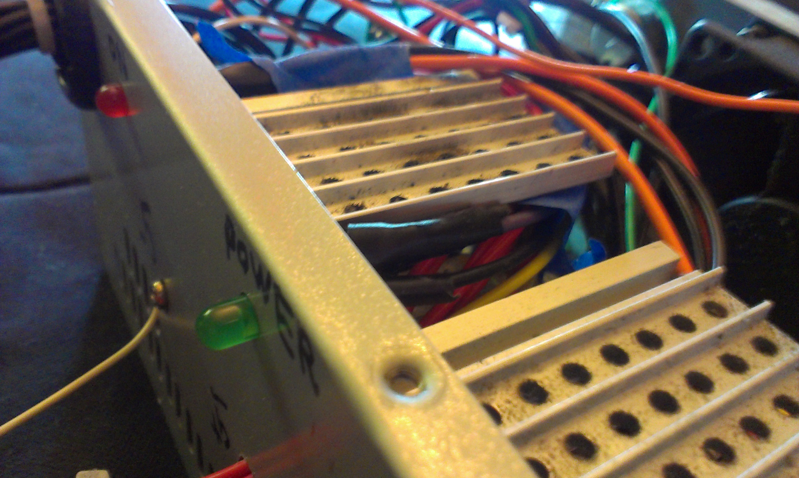 If you want an LED to be on whenever the powersupply has power - even if the power supply isn't on - you can use the purple wire, which is labelled as the +5V standby pin. So, just connect an LED+resistor combination that can deal with a 5VDC connection.
To mount the LED, I did not use any sort of clips or brackets. I just drilled a hole and taped the wires so the LED should stay in place. It isn't fool proof or professional looking, but it gets the job done.
Organizing Leads
This is the most creative part of the project. You can drill holes, use the existing hole, or try to wedge them through the grill of the plate. I opted to try them all. I wanted to have the most seperation between each of the different types of leads. This allowed me to also label them.
There are definitely some much more elegant solutions to this, such as using banana / twist mounts ( binding posts ) instead of exposing the wires. The case could also be removed altogether and simply put the power supply directly into your project's chasis.
DJI ESC and Brushless Motor
DJI ESC and Brushless MotorIndrocution
These parts are designed to be used in a quadrocopter. They are sold as replacement parts to pre-built quadrocopters, but work well as interchangable parts. This is documention on the specs and how to use the parts, since none is really provided.
I have modelled these parts in Creo Parametric. However, since I am using the student edition, it would likely be uselless to anyone who wants the part for their own project since it supposedly will only work with other student licenses. Furthermore, I'm not sure the license would even allow me to do that. I am not aware of a reason why I can't show you the results of the model like diagrams and renders though.
DJI ESC
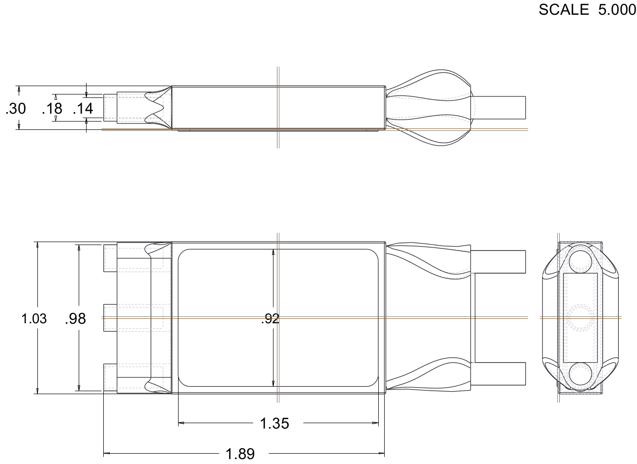
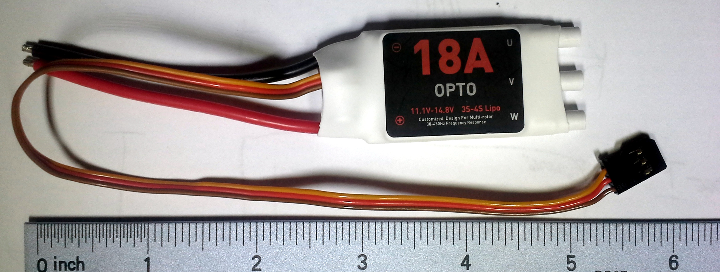
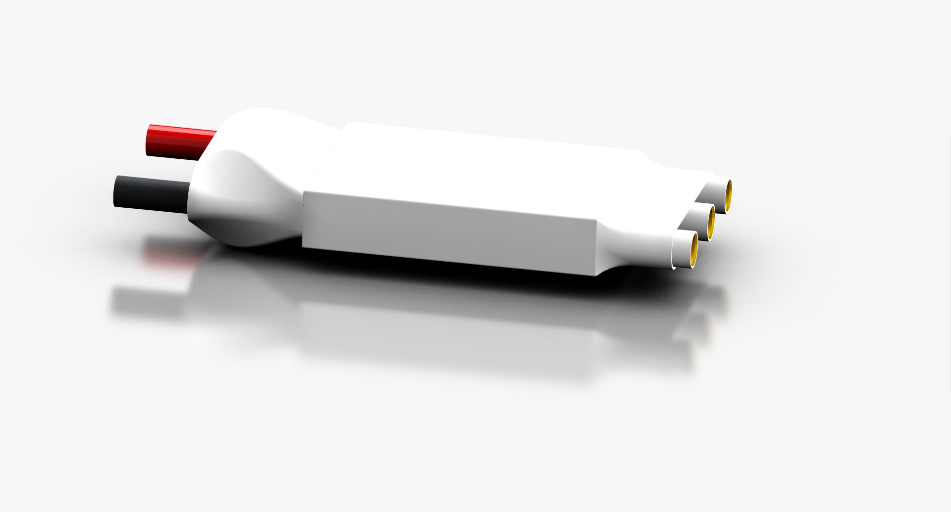
Note that I did not bother to dimension the lump where the wires come out because the shape is so irregular and varies between each individual one.
Specs
The name on the label is simply 18A. You could call it a DJI Opto-coupled electronic speed controller.
| Current | Voltage | Battery Compatibility | Frequency Response |
|---|---|---|---|
| 18 A | 11.1-14.8V | 3S-4S LiPo | 30-450 Hz |
When I weighed it I found it is 0.815 oz. The ESC outputs 3.33V on the red wire.
Signal
Some ESCs have a complicated (and undocumented) startup routine. It allows them to calibrate their input signal range. In this case, we have such control over our controller that it is substantially easier to calibrate the controller than the ESC.
According to the DJI wiki on the ESC, as well as the sticker on the actual device, it can accept signals from 30 Hz to 450 Hz. The Arduino Servo library outputs a pulse every 20ms, which translates to a frequency of 50Hz, which is within the allowable range. To set the speed, use Servo.writeMicroseconds( pulseDuration ). According to Arduino, a servo can be set to no speed with a by passing the parameter a value of 1000 uS, and full speed by passing 2000. However, according to this wiki specifically about ESCs, the range is typically from 500 uS to 2500 uS. This specific one seems to take a range from 1150 to 1950.
Motor
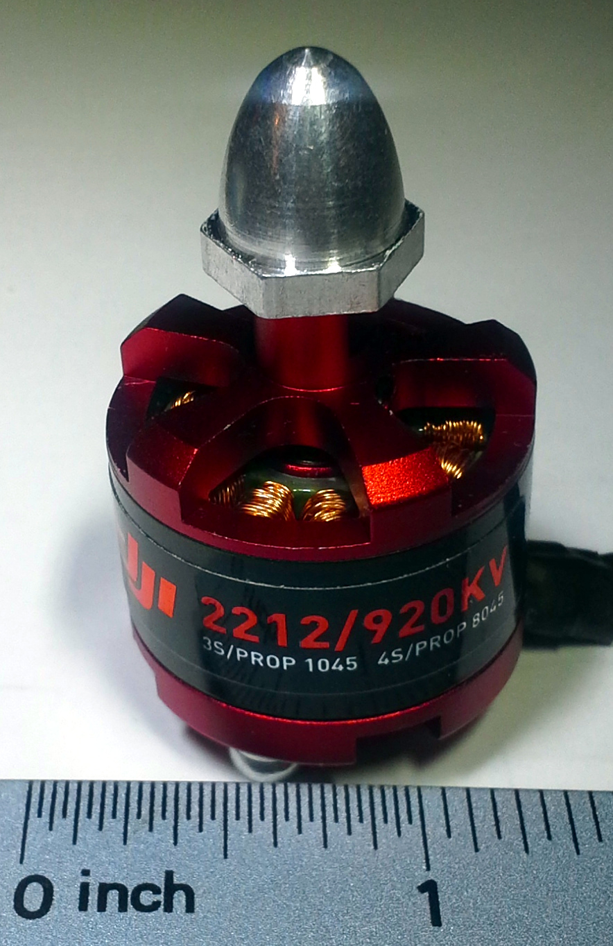


Specs
The full name as far as I can tell, is: DJI Brushless outrunner 2212/920K Motor F330-550.
| rpm/V | Shaft | 3S Battery / Prop | 4S Battery / Prop | Current | Max Current |
|---|---|---|---|---|---|
| 920 kv | 8mm | 11.1V / 10x4.5 | 14.7V / 8x4.5 | 15-25A | 30A |
I have weighed it myself at 1.980 oz (56.1321 grams). It is about 1.25 inches in diameter, and about 2 inches tall.
Lift Test
I tested the signal ranges for the ESC and the corresponding lifts for two kinds of DJI propellers.
Parts
- DJI 30A ESC
- DJI 2212 920kv motor
- An aluminum/steel beam about 1/8" thick to mount the motor to
- 2 to 4 M3 (3mm) screws
- 2 to 4 M3 (3mm) lock washers
- Drill
- Drill bits capable of drilling into metal
- 9/64" drill bit for outer mounting holes
- 9/32" drill bit for inner shaft hole
- A power supply capable of 11-13v at 18 A
- Use a very expensive lab power supply
- OR a hacked desktop computer power supply
- Use 12v rails
- Must support at least 18A on 12V rails
- I used a Cooler Master Extreme Power Plus 500W
- A block of wood (2x4, 4x4, etc)
- DJI 8045 (8" diameter) propeller
- DJI 1045 (10" diameter) propeller
- A food scale or more scientific scale with a range of about 0-8lb
- Clamps
Wiring
The wiring is easy. I made a fritzing model of it though. You can download my parts at the bottom of this page.
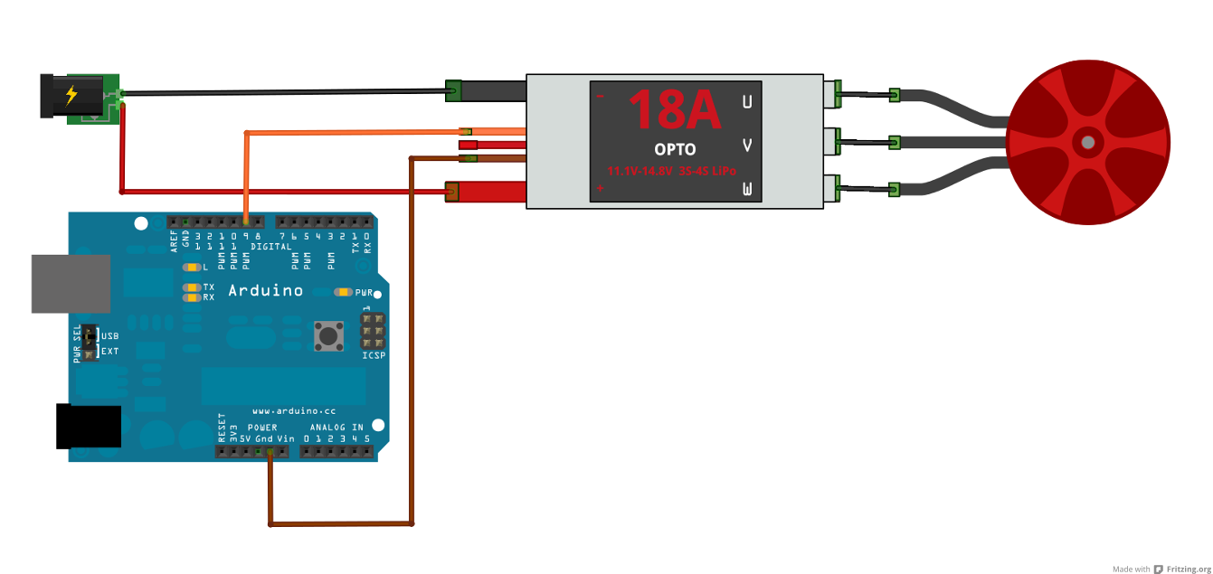
The ESC outputs a well regulated 3.33V on the small red wire, which is enough for some microcontrollers and Arduinos, but not the Arduino Uno or Mega. So the Arduino Uno would need a seperate power souce. The data pin can be any pin that the Servo library can use.
Setup
Using a desktop computer power supply capable of powering 36A of 12V to power the ESC and motor, it should have more than sufficient power. The testing rig was a very quickly put together device just intended to keep it firmly in place on the scale. The scale was not a particularly accurate one either, but it worked reasonably well.

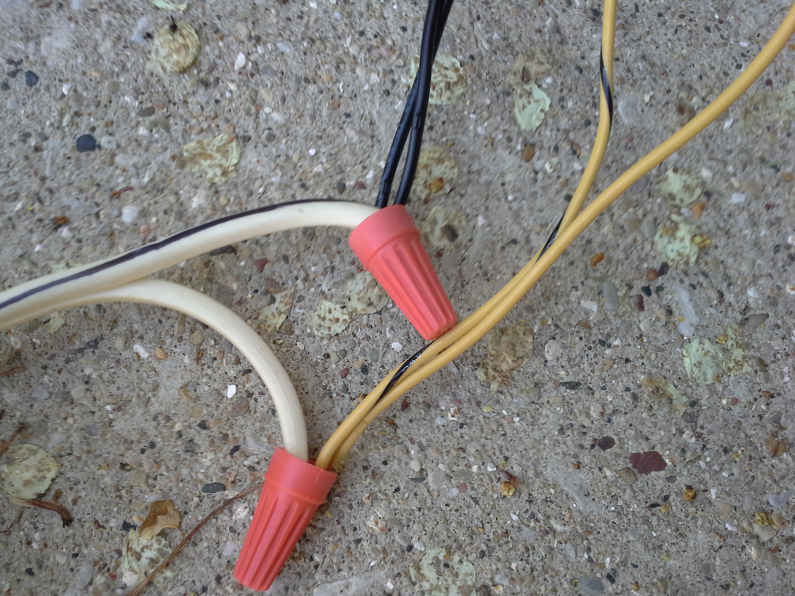
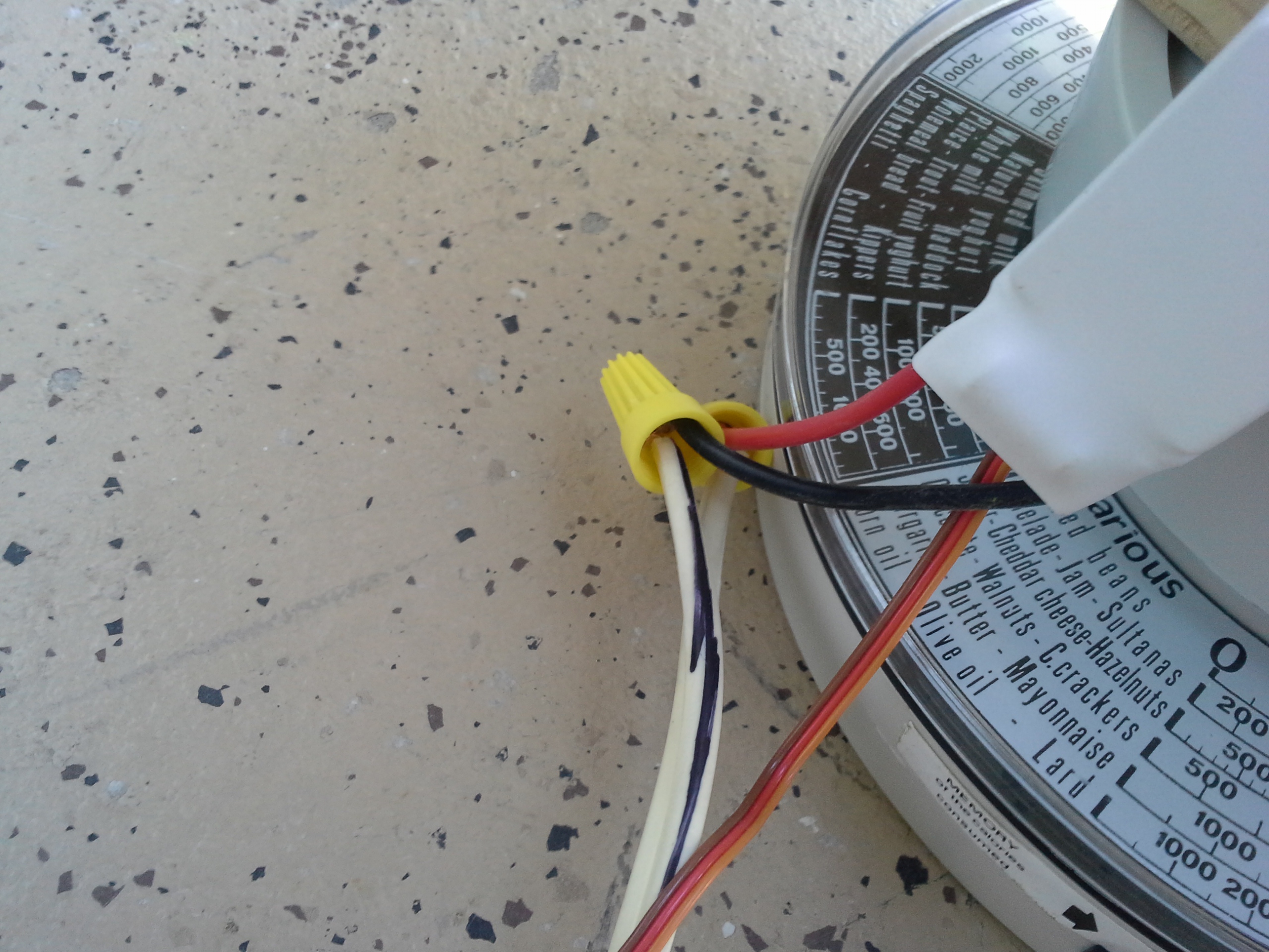
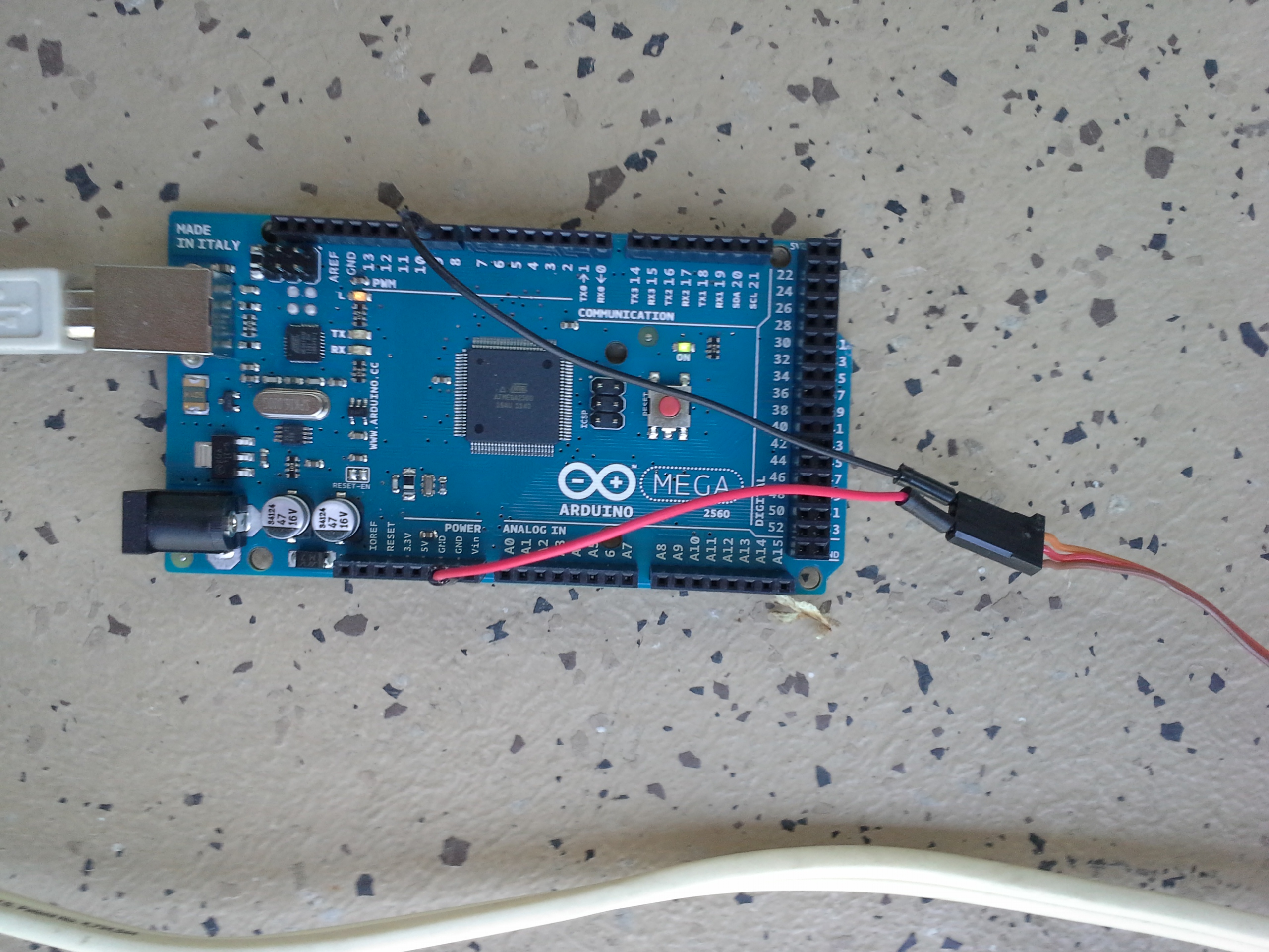
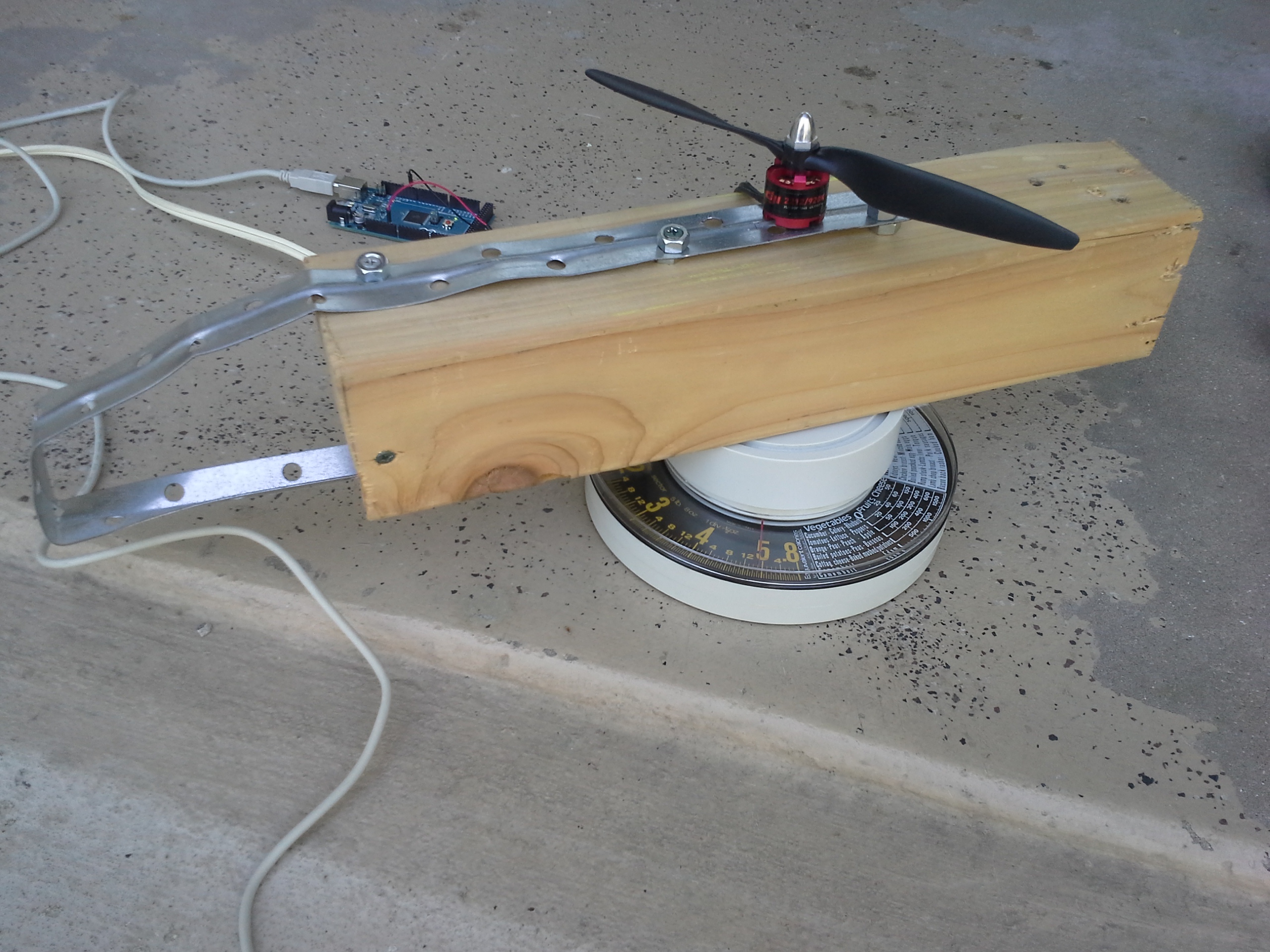
Results
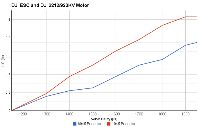
The most lift achieved on the 10" propeller was 1 pound. The most lift achieved on the 8" propeller was about 3/4 of a pound with a servo delay of 1950 microseconds.
A lot about the test is not perfectly accurate for my needs. It used 12v instead of 11.1. Also, the scale that was used was not very accurate either since the readings could be easily read wrong by an ounce. Furthermore, due to the off-center nature of the mounting bracket, the weight on the scale may not have been read perfectly well. Still, it provides a good guideline for how much the combination of parts can lift.
Most importantly, the 4 by 4 blocked more of the airflow than any chassis would, so one might expect to get even more lift than these measurements.
It also should be observed that there was no additional lift after 1900 on the 10" propeller, but the 8" one saw an increase. This could suggest that the ESC is reaching its amperage limit of 18A.
The motor was noticably warm after the 10" test, but was not at all during the 8" test. This leads me to believe that the 8" propeller would be substantially more efficient, if you don't need the extra lift.
Test Code
#include <Servo.h>

Servo myservo;  // create servo object to control a servo

int val;    // variable to read the value from the analog pin

void setup()
{
  Serial.begin(9600);
  myservo.attach(9);  // attaches the servo on pin 9 to the servo object
}

void loop()
{
  val = 1050;
  delay(500);
  myservo.writeMicroseconds(val);
  Serial.println(val);
}
Divergence Meter
Divergence MeterBackstory
I want to make a divergence meter. A divergence meter is not a real thing. It's a fictional device from Steins;Gate to tell if the worldline (timeline) has changed substantially from an original world line (the alpha) - following the time travel theory popularized by John Titor. If you've never seen the show, you might still be interested in how to wire up a longer string of displays to get 8 digits instead of being stuck with just 4.
Goals
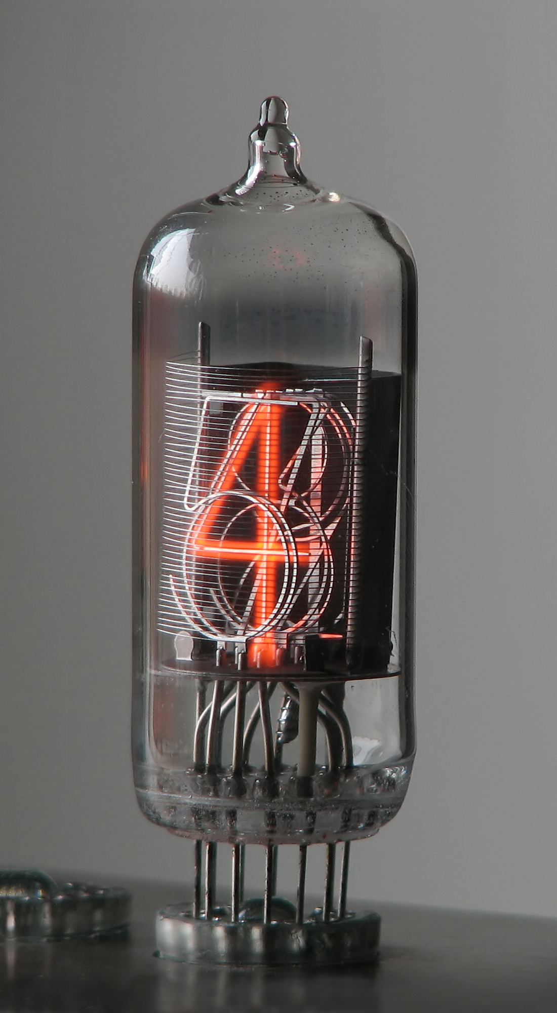
I'm not actually going to build a very accurate one. It turns out that that many Nixie tubes are kind of expensive (about $100), but you really should use them if you want to maintain authenticity. There are plenty of other tutorials on how to make one with nixie tubes, and you can even buy an offical one, which admittedly does not look all that accurate. The show specifically references Nixie tubes' cool factor, so it's really an important detail.
Also, it is obviously not going to be able to actually measure the attractor field, so it will instead randomly make up divergence values at random times. Also, according to canon, the divergence meter should cycle random numbers on the display quickly while the divergence number is changing for about a second.
To somewhat replicate its purpose, this system will change divergence number about once a day or perhaps longer. One could look to the divergence meter to try making a small change in their life. Very infrequently, the divergence number should jump to something above 1%. Larger numbers could be cause for celebration or trying larger changes in one's life.
Parts
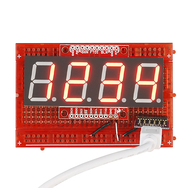
If you choose to build yours with nixie tubes, your parts list will vary greatly from this, since you will also have to wire each segment to up seperately to your microcontroller, but also need to worry about power management. Nixie tubes need high voltage and low current, so switching segments on and off might require something like a high power shift register, or a logic level shifter to protect your Arduino microcontroller.
- 2x OpenSegment Serial Displays 20mm or 12.8mm (Sparkfun, $17ea)
- Hard Wire (8 segments)
- Arduino Micro without headers (Adafruit, $23)
- Enclosure for two displays side by side and a micro
- should leave micro USB port exposed or use a panel mount
The above parts list assumes you will want to solder the whole thing together permanently.
The total cost for this project, without using nixie tubes, is only about $57 plus whatever you use to make the case with. It is substantially safer, cheaper, and easier to make.
Wiring
The wiring here could not be easier if you're using the serial seven segment displays. The nixie tubes, however, will be nightmarish and will probably require making your own printed circuit board (PCB) to keep your sanity and to keep the device compact.
Change the i2c Address
Only hook up the first seven segment display. If you keep both on, you will have a problem due to the fact that both of the displays have the same address. So, both would react to the same commands. Fortunately, it can be easily changed with the right command code (0x80). By default, the address is 0x71. Change the address of the first display to just about anything but that. So, with just one display connected, run this:
#include <Wire.h>
void setup() {
  Wire.beginTransmission( 0x71 );   // Start I2C transmission to first display
  Wire.write( 0x80 );               // I2C Address Config command
  Wire.write( 0x42 );               // Set 7-bit address to 0x42
  Wire.endTransmission();           // Stop I2C transmission
}
void loop() {}
Connections
You will probably want to solder these connections instead of using headers and pins because it will save space and cost. However, it will make the changes somewhat more permanent. On the bright side, if you later decide you don't want a divergence meter, you can actually have it display just about anything - like the time perhaps.
To hook up these displays, simply connect the SDA and SCL pins on the Arduino Micro microcontroller to the SDA pin on the SDA and SCL pins on the display respectively. Likewise, connect the 5V from the Arduino to the + on the display, and the GND on the Arduino to the - on the display. Again, only do this for the one display.
Once you change the address of the first display, you can actually hook the other display up to the same wires. It might sound weird at first, but that's how i2c works. Check the sparkfun tutorial and see for yourself. The smaller serial7segment displays have a +,-,SDA, and SCL pin on each side to pass the connection through to the next one easily. You can do this yourself with just some wire though.
Code
#define DISPLAY1 0x71
#define DISPLAY2 0x42

#include <Wire.h>

unsigned long divergence = 337187; //or 409031
// displayed as:         0.337187

//Given a string, i2cSendString sends the first four characters over i2c
void i2cSendString(char *toSend, int addr) {
  Wire.beginTransmission(addr); // transmit to device #1
  for(byte x = 0 ; x < 4 ; x++) {  // for each of the 4 characters
    Wire.write(toSend[x]);         // Send the character from the array
  }
  Wire.endTransmission();          // Stop I2C transmission
}

void updateDisplay() {
  char first[5];
  char second[5];

  snprintf( first , 5, "%05d", divergence / 10000UL ); //pad with 0
  snprintf( second, 5, "%05d", divergence % 10000UL ); //pad with 0

  //move the second number to first place, then replace with space
  //it looks weird, but that's how the divergence meter is in the show
  first[0] = first[1];
  first[1] = ' ';

  i2cSendString(first , DISPLAY1);
  i2cSendString(second, DISPLAY2);

  Serial.print(first);
  Serial.println(second);

  // write the decimal place
  Wire.beginTransmission(DISPLAY1); // transmit to device #1
  Wire.write( 0x77 );               // send decimal command
  Wire.write( 1 << 3 );             // send the place using bitshift
  Wire.endTransmission();           // Stop I2C transmission
}

void newNumber() {
  // small percent chance to break divergence barrier
  if ( random(0, 100) < 5 ) {
    divergence = random(1000000UL, 1409031UL);
  }

  divergence = random(0UL, 999999UL);

  updateDisplay();
}


// when the divergence number changes
// the divergence meter cycles numbers randomly
// until a new number stabilizes

void changingNumber() {
  for( int cycle = 0; cycle < 100; ++cycle ) {
    divergence = random(0, 9999999UL);
    updateDisplay();
    delay( 30 );
  }
}

void setup() {

  // read the noise for some randomness
  // if analog input pin 0 is unconnected, random analog
  // noise will cause the call to randomSeed() to generate
  // different seed numbers each time the sketch runs.
  // randomSeed() will then shuffle the random function.
  randomSeed(analogRead(0));

  Serial.begin(19200); //for debugging
}

//increase this if you're impatient to change the divergence number
#define tdivider 10000UL
void loop() {

  changingNumber();
  newNumber();

  unsigned long wait = random(43200000UL , 604800000UL)  / tdivider;
  Serial.print("Waiting ");
  Serial.print(wait);
  Serial.println(" milliseconds before number change");

  delay(wait); // 12 hours to a week

}
Octobot Chassis
Octobot ChassisIntroduction
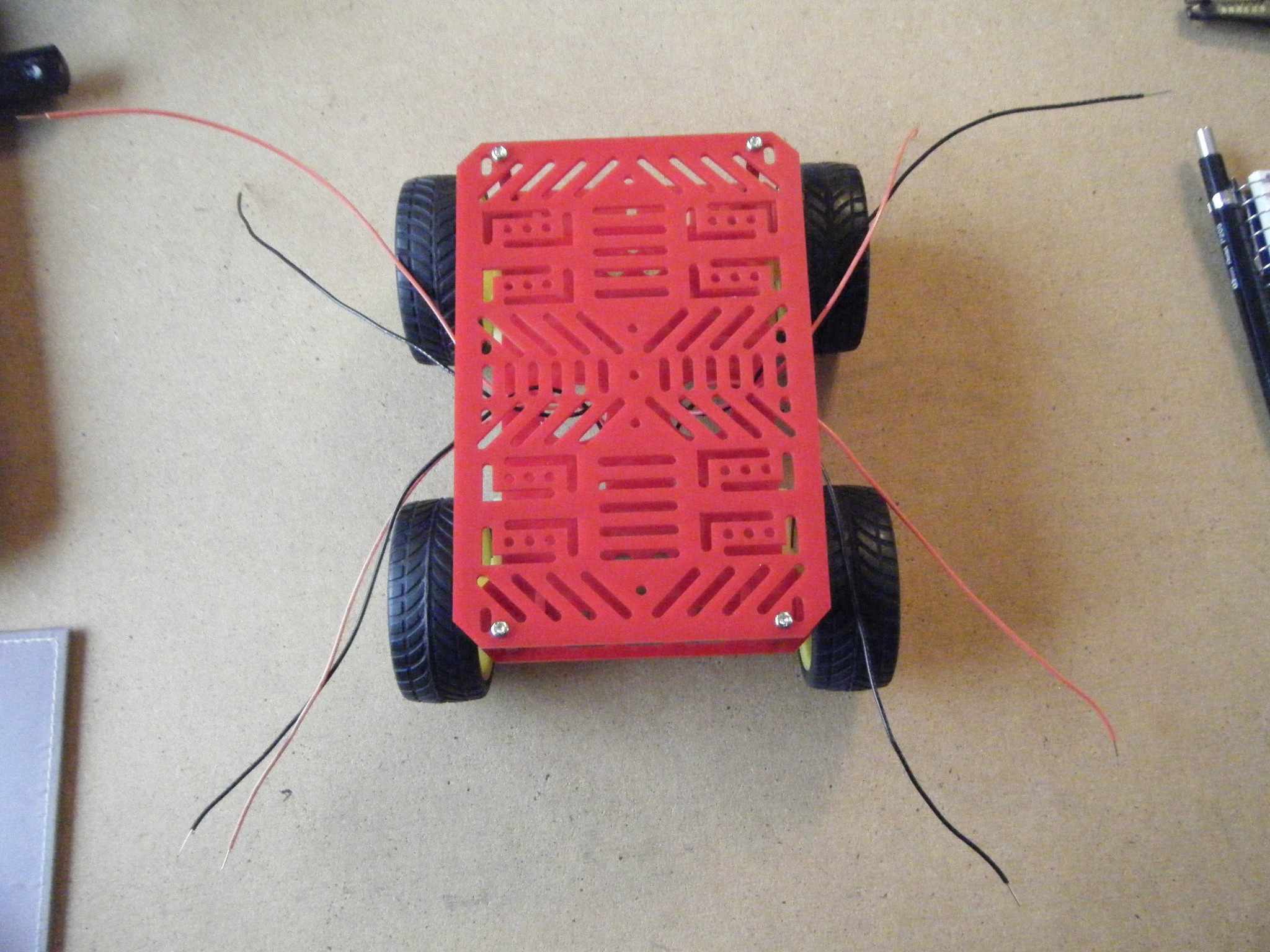 Octobot is the name of the robotic chassis that I do most of my testing on. It got it's name because it originally had eight wires sticking out because of the motors.
The picture to the right shows it in its unfinished form. The front two wheels were removed and exchanged for a ball caster for manuverability.
Once completed, the chassis makes an excellent inexpensive platform for an Arduino robot.
The Making of Octobot
Parts:
- 4WD Chassis and Motors from Jameco
- 1" Ball Caster from Pololu
- 3/8" Spacer
- Screwdriver
- Drill
- Solder and Soldering Iron
- Wires
Construction:
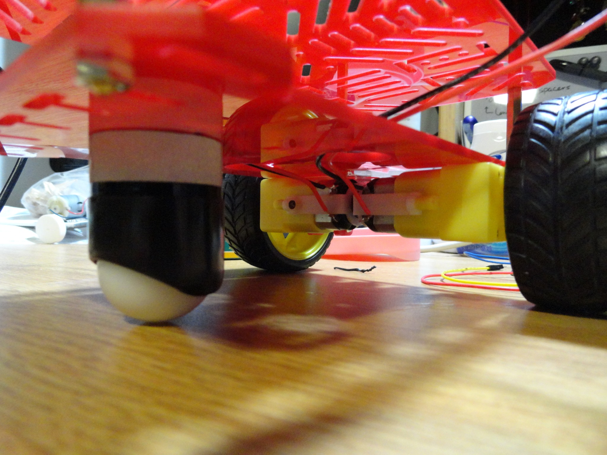 As can be seen, Octobot started out with four motors and four wheels. It was quickly discovered that this was not desirable if the robot had to perform tight turns. Therefore, Octobot was altered to have two wheels and a ball caster.
This required getting a 3/8" spacer made from aluminum to get a more appropriate height. Holes had to be drilled in the chassis to align with the ball casters holes. The alterations were fairly quick and simple to do. This is a cheaper alternative to some of the robotic platforms available.
Uses
Octobot is used to test most of the code I post if it directly pertains to use on a robot. Two arduinos can easily be attached via standoffs to the top of Octobot.
Simple Security System
Simple Security SystemIntroduction
Who hasn't wanted to monitor what goes on when they aren't there. When I was little, I was always curious about whether or not anyone was going into my room and would have loved a camera monitoring system. It may even be a good idea to have a simple security setup for an apartment.
This tutorial shows how to set up a PIR sensor along with a small TTL camera and an SD card to capture images whenever there is movement in the monitored area.
The necessary libraries are: SoftwareSerial (for the camera) and SDFat (for the SD card).
Parts
- PIR Sensor
- TTL Camera by Linksprite
- SD Card Breakout Board
- SD Card
- 2 10k Resistors
- 3 other Resistors (I'm not sure if size matters, but mine were all above 1k)
- Wires
- Arduino
Schematic
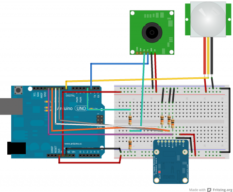
Code
Arduino
Below is the code:
/***************************
PIR Motion Detection - Camera Capture

by Jennifer Case
5/21/2013

Parts:
-PIR Sensor
-SD Card Breakout Board
-TTL Camera

Pin 2,3 - Camera
Pin 8 - PIR Sensor
Pin 10 - CS/D3
Pin 11 - CMD
Pin 12 - D0
Pin 13 - CLK
****************************/
#include <SoftwareSerial.h>
#include <SdFat.h>

//SD Card
SdFat sd;
SdFile myFile;
int picCnt = 0;

//Camera
byte incomingbyte;
SoftwareSerial cameraSerial = SoftwareSerial(2, 3);   //Configure pin 2 and 3 as soft serial port
int a=0x0000,j=0,k=0,count=0;   //Read Starting address
uint8_t MH,ML;
boolean EndFlag=0;

//Declare pins
const int chipSelect = 10;
int pirPin = 8;

void setup() {
  Serial.begin(19200); //start serial
  cameraSerial.begin(38400); //start serial with camera

  // Initialize SdFat or print a detailed error message and halt
  // Use half speed like the native library.
  // change to SPI_FULL_SPEED for more performance.
  if (!sd.begin(chipSelect, SPI_HALF_SPEED)) sd.initErrorHalt();

  SendResetCmd(); //allows camera to take pictures
  delay(3000); //delay necessary for camera reset
}

void loop() {
  int val = digitalRead(pirPin); //read from PIR sensor

  //when val is HIGH, there is motion -> take pictures
  if (val == HIGH) {
    //create title for images
    char photoTitle[25] = {};
    sprintf(photoTitle, "pic%d.txt", picCnt);
    //Serial.println(photoTitle);

    //make sure file can be created, otherwise print error
    if (!myFile.open(photoTitle, O_RDWR | O_CREAT | O_AT_END)) {
      sd.errorHalt("opening photoTitle.txt for write failed");
    }

    //Serial.print("Writing to file...");

    SendTakePhotoCmd(); //take photo
    delay(200); //delay to make sure there is no drop in the data
    //Serial.println("Start pic");

    while(cameraSerial.available()>0) {
      incomingbyte=cameraSerial.read(); //clear unneccessary serial from camera
    }
    byte b[32];

    while(!EndFlag) {
      j=0;
      k=0;
      count=0;
      SendReadDataCmd(); //command to get picture from camera

      delay(75); //delay necessary for data not to be lost
      while(cameraSerial.available()>0) {
        incomingbyte=cameraSerial.read(); //read serial from camera
        k++;
        if((k>5)&&(j<32)&&(!EndFlag)) {
          b[j]=incomingbyte;
          if((b[j-1]==0xFF)&&(b[j]==0xD9))
          EndFlag=1; //when end of picture appears, stop reading data
          j++;
          count++;
        }
      }

      for(j=0;j<count;j++) { //store picture into file
        if(b[j]<0x10)
          myFile.print("0");
        myFile.print(b[j], HEX);
      }
      myFile.println();
    }

    StopTakePhotoCmd(); //stop this picture so another one can be taken
    EndFlag = 0; // reset flag to allow another picture to be read
    //Serial.println("End of pic");

    myFile.close(); //close file
    //Serial.println("done.");
    //Serial.println();

    picCnt++; //increment value for next picture
  }
}

//Send Reset command
void SendResetCmd() {
  cameraSerial.write((byte)0x56);
  cameraSerial.write((byte)0x00);
  cameraSerial.write((byte)0x26);
  cameraSerial.write((byte)0x00);
}

//Send take picture command
void SendTakePhotoCmd() {
  cameraSerial.write((byte)0x56);
  cameraSerial.write((byte)0x00);
  cameraSerial.write((byte)0x36);
  cameraSerial.write((byte)0x01);
  cameraSerial.write((byte)0x00);

  a = 0x0000; //reset so that another picture can taken
}

void FrameSize() {
  cameraSerial.write((byte)0x56);
  cameraSerial.write((byte)0x00);
  cameraSerial.write((byte)0x34);
  cameraSerial.write((byte)0x01);
  cameraSerial.write((byte)0x00);
}

//Read data
void SendReadDataCmd() {
  MH=a/0x100;
  ML=a%0x100;

  cameraSerial.write((byte)0x56);
  cameraSerial.write((byte)0x00);
  cameraSerial.write((byte)0x32);
  cameraSerial.write((byte)0x0c);
  cameraSerial.write((byte)0x00);
  cameraSerial.write((byte)0x0a);
  cameraSerial.write((byte)0x00);
  cameraSerial.write((byte)0x00);
  cameraSerial.write((byte)MH);
  cameraSerial.write((byte)ML);
  cameraSerial.write((byte)0x00);
  cameraSerial.write((byte)0x00);
  cameraSerial.write((byte)0x00);
  cameraSerial.write((byte)0x20);
  cameraSerial.write((byte)0x00);
  cameraSerial.write((byte)0x0a);

  a+=0x20;
}

void StopTakePhotoCmd() {
  cameraSerial.write((byte)0x56);
  cameraSerial.write((byte)0x00);
  cameraSerial.write((byte)0x36);
  cameraSerial.write((byte)0x01);
  cameraSerial.write((byte)0x03);
}
This code sets up the SD card, reads from the PIR sensor and then takes pictures while there is motion. Everytime a picture is taken, the name of the file is incremented up.
Python
The Python code from the camera tutorial has been revamped to allow for multiple photos to be processed at a time. This is set up to work with the naming given in the above code. The user may still have to adjust the range depending on the number of photos.
#!/usr/bin/python
# open file
import binascii

count = 0

for count in range (0,4):

    f = open ("PIC%d.txt" % (count),"r")
    nf = open("IMAGE%d.jpg" % (count),"wb")

    #Read whole file into data
    while 1:
        c = f.readline()
        d = c.strip()
        #print (c)
        #print (d)
        if not c:
            break
        nf.write(binascii.a2b_hex(bytes(d, "ascii")))


    # Close the file
    f.close()
    nf.close()
Sample Images
Here are a couple proof of concept images showing that the camera and motion detection works.


Inverted Pendulum Controls
Inverted Pendulum ControlsIntroduction
Balancing an inverted pendulum is the typical example when demonstrating a control system. A weight on an arm above the rotation pivot is an unstable system. It has one stable point when the weight is perfectly balanced. If the weight is slightly on either side of this point it will begin to move away from this stable point. On the other hand, a weight on an arm below the rotation pivot is a stable system. The weight is stable at the point exaclty below the pivot as well, but if it is moved slightly away from this point it will move back towards it.
I have built a simulation using web standards like JavaScript and HTML so you can observe the impact different PID controls have on an inverted pendulum. You can modify the gains of the proportional, integral, and derivative controls to test how each component works. The simulation is optimized to be used with Chrome and Firefox, but has a limited set of features available for Internet Explorer.
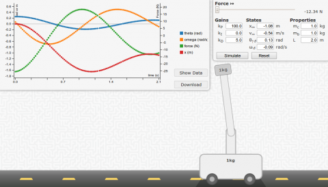
A screenshot of the simulation. Click to do your own simulations.
The simulation physics are done using techniques taught in Dr Brianno Coller's Computational Methods course including RK4 integration.
Simulation Usage
The simulation is designed to be very easy to use. Here are some steps to run your own test.
- Modify the control gains, initial states, and properties of the system
- Click "simulate".
- Observe the behavior of the system. In particular, watch the direction the forces are being applied by the controller, and how well the weight is being balanced.
- When done, click "stop". The simulation can be run for several minutes - much longer and it may become unresponsive due to the accumulation of many data points.
- A graph will appear. You can show and hide variables by clicking on them in the legend. You can also download the data in CSV format by clicking the "download" button. If using Internet Explorer, the "show" button must be used, and data can be copied manually.
- Click "reset". Repeat (go to step 1).
Dynamics
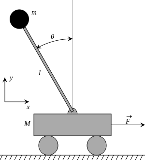
The true diferential equations for the motion of the system can be found on Wikipedia.
![]()
![]()
In some derivations, the centripital acceleration force due to the angular velocity is left out. The dynamics in this simulation does not rule out this term. However, it may be safe to neglect the term when designing the control system due to the fact that a balanced pendulum should have low velocity.
To simulate these dynamics, the second derivatives are isolated to one side of each equation. Then each second order equation is turned into two first order equations. Finally, they are solved using numerical integration by using the RK4 method.
PID Controls
| Angle | Error |
| 15° | 1.1% |
| 30° | 4.5% |
| 60° | 17.3% |
| 90° | 36.3% |
| 120° | 58.6% |
| 150° | 80.9% |
| 180° | 100.0% |
The control system used in the simulation is a basic, linearized control system. Using the small angle approximation that ![]() , the control system can be simplified. While the approximation holds true for angles close to zero (sin0 = 0), at larger values the approximation gets worse.
, the control system can be simplified. While the approximation holds true for angles close to zero (sin0 = 0), at larger values the approximation gets worse.
Note that θ = 0 when the pendulum is upright.
The control system then becomes:
F = - kP * θ - kD * ω - kI * ∫ θ dt
The gains then can be modified depending on the properites like mass and pendulum length.
A systematic way to iteratively improve a design is to try a pair of values and observe if there is overshoot and how much. Overshoot is the overcorrection for an error - or the amplitude "wobble" on the bar. Also, observe the settle time - or the time it takes for a the system to reach its steady-state. The settle time is the time it takes for the bar to stop wobbling.
If there is a lot of overshoot, try decreasing kP or increasing kD. If there is a long settle time, try increasing kP. kI is used to eliminate steady-state error. This would be if the pendulum were to balance for a prolonged period at a position other than vertical.
Udoo
UdooBasic Features
The Udoo is relatively pricey, but has some great features and is relatively well documented. They bill themselves as a "Raspberry Pi + Arduino", but that is selling themselves a little short. Anyone could plug an Arduino into the USB port of a Raspberry Pi. The ARM processor is faster and more capable than the Raspberry Pi, but also has the same pinout as the Arduino Due with the exception of a few missing pins like the analog ones. Additionally, there is an Arduino Due-like processor that has full access to the same pins. That's right. Both processors can access the same pins. They can access different ones at the same time, or even send signals to each other if you configure it that way.
It features an ARMv7 processor, not ARMv6 like the Raspberry Pi. The newer instruction set means each core of the ARM processor is significantly (2x) faster at many tasks. More importantly, it is the same instruction set supported by popular Linux distrobutions like Ubuntu and Android. The Raspberry Pi's ARMv6 processor is pretty much restricted to the Raspbian Debian derivative.
Purchasing
It took exactly 1 week for SECO USA to ship to my address in the US. They shipped it from Italy, apparently. There are very few details on shipping deadlines and they never notified me that they even shipped the thing, let alone give me a tracking number. Even after I received it, the order was still listed as "processing". I contacted their support, which responded fairly qucikly, and this is apparently standard procedure. The shipping method is referred to as "FCA shipping", but it was fullfilled through UPS. As a result of the lack of transparency and risk of delay due to the fact that it came from oversees, I might suggest purchasing the Udoo from Maker Shed instead if you are in the US.
I would not recommend using the SD card in their accessories package. It is class 4 and is noticably slower than a class 10. Painfully slow, actually. The udoo itself is actually plenty fast, and capable of using the class 10 speed. I ran a benchmark using palimptest (gnome-disk-utility) and a $14 16GB class 10 SanDisk SDSDQU-016G-AFFP-A managed to pull 21.1 MB/s read with a 1ms access time, which is well above even the class 10 spec. Benchmarks run on class 4's tend to be more in the 4-5MB/s. One of the great features of the Udoo is its speed, so I don't know why you would skimp on such an important feature. A lot of class 4's are actually more expensive than 10's depending on where you buy them. I thought it might even be worthwhile going for one of the Extreme lines that promise 90MB/s. It turns out the speed is limited to 21.4MB/s on the uSD card, so the socket can't quite deliver the same speed of SATA. All that being said, the accessories package has some other cool things like a SATA power adapter and an SSD would be many times faster than any uSD card. I wonder if it is SATA I, II, or III though. The documentation does not seem to say anywhere, but this page has a benchmark where the SATA plug goes up to 110 MB/s read on the same palimptest.
Setup
The documentation on udoo.org/getting-started are maybe a little too basic for most users. All you really need are to download the latest Ubuntu image from here, and write it to the uSD card using these instructions.
Here are some packages I would strongly recommend:
sudo apt-get install bash-completion python-smbus
Here are some others I would also recommend:
- midori: A lightweight web browser
- guvcview: Way to preview webcams to see if they are working and tinker with settings
- sparkleshare: Dropbox-like syncronization using git
- vlc: plays everything
- qalqulate-gtk: great calculator that even does algebra
- minicom: command line viewer for RX/TX serial
Add some swap
Probably one of the most limiting features of the Udoo is its 1GB RAM. It is pretty easy to run out of memory pretty quickly with the default installation, and when you do things get bad fast. Processes start crashing until there is some free memory again. What is slightly less bad than that? Writing some of that memory to the slow SD card. If you do this a lot, the SD card may slowly degrade since there is a limited number of writes you can do. Still, it seems preferable to the alternative which is guaranteed crashing. So, look into adding a swapfile or a swap partition. Partitions are easy to do in gparted. It's pretty easy to do and well documented elsewhere, so I won't do it here.
Pinout
Pin Muxing
To change the pin mode you have to change a .h file in the kernel source recompile the kernel. This can be done according to the manual, but they leave out exactly how to compile a kernel, which is maybe the more daunting of the two tasks. There is a pretty detailed tutorial here.
wget https://github.com/UDOOboard/Kernel_Unico/archive/master.zip
unzip master.zip
cd Kernel_Unico-master

nano arch/arm/mach-mx6/board-mx6qd_seco_UDOO.h # modify the pinout here

sudo apt-get install ncurses-dev
make menuconfig
make -j5 uImage modules # makes using 5 cores

sudo cp /boot/uImage /boot/uImage.bak #make a backup copy of the old uImage
sudo cp arch/arm/boot/uImage /boot/uImage
sudo make modules_install
sudo rm /usr/src/linux && sudo ln -s . /usr/src/linux
The actual compile process took less than 15 minutes for me. Probably less, but I wasn't watching that closely. The wget and unzip may have actually taken longer if that's even possible.
Networking Notes
The wireless chip is actually on the same USB hub as the two external ports. This means that the wireless speeds will be limited to USB 2.0 speeds and that it will compete for the same USB throughput as other devices like thumb drives, hard drives, or webcams. The wireless chip that comes on it is actually wireless 802.11 N compatible, but probably is not capable of any great speed increase. It is a Ralink RT5370 with the USB ID 148f:5370. This chip may be able to go into Master / Access Point mode, but I have not managed to do so yet.
Somewhere when considering purchasing the Udoo I saw that the gigabit ethernet speeds were somewhat limited. I did a speedtest on my 100mbit line and was able to get 90-80 Mbit/s. I did not test a full gigabit LAN connection.
Installing OpenCV
The default OpenCV is quite old due ot the two year old Ubuntu release, and has a couple bugs in it. As a result, download the newest version from the website:
sudo apt-get install gcc g++ cmake build-essential libgtk2.0-dev pkg-config python-dev libavcodec-dev libavformat-dev libswscale-dev libjpeg-dev libpng-dev libtiff-dev libjasper-dev libavcodec-dev libavformat-dev libswscale-dev libdc1394-22-dev libxine-dev libgstreamer0.10-dev libgstreamer-plugins-base0.10-dev libv4l-dev
wget # find url from http://opencv.org/downloads.html
tar -xvf opencv-*
cd ???/release
cmake -D CMAKE_BUILD_TYPE=RELEASE -D CMAKE_INSTALL_PREFIX=/usr/local -D BUILD_NEW_PYTHON_SUPPORT=ON -D BUILD_EXAMPLES=ON -D ENABLE_NEON ON ..
make -j 5 # will probably take a very long time (hour+)
sudo make install
Udoo Benchmarks
Udoo BenchmarksIntroduction
Each test was run on an Udoo with a Quad core while X.org was running and a Chromium window was open. The additional load, for the most part, is not important because most these benchamarks only test one of the cores of the udoo at a time. Only the 7zip test ran accross all cores.
To compare the benchmarks to those of the Raspberry Pi (wiki), I used this package (zip). Also compare to my Angstrom BeagleBone Black test .
Dhrystone (no compiler optimization)
At 1,048,252 dhrystones per core, each core with the unoptimized compile is about as fast as a Raspberry Pi with an optimized compile.
$ gcc dhry_1.c dhry_2.c dhry.h cpuidc.c -lpthread -lrt -o dhry
$ ./dhry
##########################################

Dhrystone Benchmark, Version 2.1 (Language: C or C++)

Optimisation    Opt 3 32 Bit
Register option not selected

       10000 runs   0.03 seconds
      100000 runs   0.15 seconds
      200000 runs   0.20 seconds
      400000 runs   0.38 seconds
      800000 runs   0.76 seconds
     1600000 runs   1.51 seconds
     3200000 runs   3.05 seconds

Final values (* implementation-dependent):

Int_Glob:      O.K.  5  Bool_Glob:     O.K.  1
Ch_1_Glob:     O.K.  A  Ch_2_Glob:     O.K.  B
Arr_1_Glob[8]: O.K.  7  Arr_2_Glob8/7: O.K.     3200010
Ptr_Glob->              Ptr_Comp:       *    98680
  Discr:       O.K.  0  Enum_Comp:     O.K.  2
  Int_Comp:    O.K.  17 Str_Comp:      O.K.  DHRYSTONE PROGRAM, SOME STRING
Next_Ptr_Glob->         Ptr_Comp:       *    98680 same as above
  Discr:       O.K.  0  Enum_Comp:     O.K.  1
  Int_Comp:    O.K.  18 Str_Comp:      O.K.  DHRYSTONE PROGRAM, SOME STRING
Int_1_Loc:     O.K.  5  Int_2_Loc:     O.K.  13
Int_3_Loc:     O.K.  7  Enum_Loc:      O.K.  1
Str_1_Loc:                             O.K.  DHRYSTONE PROGRAM, 1'ST STRING
Str_2_Loc:                             O.K.  DHRYSTONE PROGRAM, 2'ND STRING


From File /proc/cpuinfo
Processor	: ARMv7 Processor rev 10 (v7l)
processor	: 0
BogoMIPS	: 790.52

processor	: 1
BogoMIPS	: 790.52

processor	: 2
BogoMIPS	: 790.52

processor	: 3
BogoMIPS	: 790.52

Features	: swp half thumb fastmult vfp edsp neon vfpv3
CPU implementer	: 0x41
CPU architecture: 7
CPU variant	: 0x2
CPU part	: 0xc09
CPU revision	: 10

Hardware	: SECO i.Mx6 UDOO Board
Revision	: 63012
Serial		: 021111d4dbc7884d


From File /proc/version
Linux version 3.0.35 (udoo@ubuntu) (gcc version 4.4.4 (4.4.4_09.06.2010) ) #1 SMP PREEMPT Sat Oct 12 14:05:30 CEST 2013


Nanoseconds one Dhrystone run:       953.97
Dhrystones per Second:              1048252
VAX  MIPS rating =                   596.61
Dhrystone (O3 compiler optimization)
With over 2,809,990 dhrystones per second, each core of the Udoo quad is essentially three Raspberry Pi's. I thought maybe it was using the extra cores, and ran the test while using top to see that it is, in fact, only using 100% CPU (not 300%+). The BeagleBone Black with Ubuntu ran at 3,319,960 dhrystones per second, so it is roughly as fast as that.
gcc dhry_1.c dhry_2.c dhry.h cpuidc.c -lpthread -lrt -O3 -o dhry
ubuntu@imx6-qsdl:~/Downloads/Raspberry_Pi_Benchmarks/Source Code$ ./dhry
##########################################

Dhrystone Benchmark, Version 2.1 (Language: C or C++)

Optimisation    Opt 3 32 Bit
Register option not selected

       10000 runs   0.01 seconds
      100000 runs   0.11 seconds
      200000 runs   0.08 seconds
      400000 runs   0.14 seconds
      800000 runs   0.29 seconds
     1600000 runs   0.57 seconds
     3200000 runs   1.15 seconds
     6400000 runs   2.28 seconds

Final values (* implementation-dependent):

Int_Glob:      O.K.  5  Bool_Glob:     O.K.  1
Ch_1_Glob:     O.K.  A  Ch_2_Glob:     O.K.  B
Arr_1_Glob[8]: O.K.  7  Arr_2_Glob8/7: O.K.     6400010
Ptr_Glob->              Ptr_Comp:       *    94584
  Discr:       O.K.  0  Enum_Comp:     O.K.  2
  Int_Comp:    O.K.  17 Str_Comp:      O.K.  DHRYSTONE PROGRAM, SOME STRING
Next_Ptr_Glob->         Ptr_Comp:       *    94584 same as above
  Discr:       O.K.  0  Enum_Comp:     O.K.  1
  Int_Comp:    O.K.  18 Str_Comp:      O.K.  DHRYSTONE PROGRAM, SOME STRING
Int_1_Loc:     O.K.  5  Int_2_Loc:     O.K.  13
Int_3_Loc:     O.K.  7  Enum_Loc:      O.K.  1
Str_1_Loc:                             O.K.  DHRYSTONE PROGRAM, 1'ST STRING
Str_2_Loc:                             O.K.  DHRYSTONE PROGRAM, 2'ND STRING


From File /proc/cpuinfo
Processor	: ARMv7 Processor rev 10 (v7l)
processor	: 0
BogoMIPS	: 790.52

processor	: 1
BogoMIPS	: 790.52

processor	: 2
BogoMIPS	: 790.52

processor	: 3
BogoMIPS	: 790.52

Features	: swp half thumb fastmult vfp edsp neon vfpv3
CPU implementer	: 0x41
CPU architecture: 7
CPU variant	: 0x2
CPU part	: 0xc09
CPU revision	: 10

Hardware	: SECO i.Mx6 UDOO Board
Revision	: 63012
Serial		: 021111d4dbc7884d


From File /proc/version
Linux version 3.0.35 (udoo@ubuntu) (gcc version 4.4.4 (4.4.4_09.06.2010) ) #1 SMP PREEMPT Sat Oct 12 14:05:30 CEST 2013


Nanoseconds one Dhrystone run:       355.87
Dhrystones per Second:              2809990
VAX  MIPS rating =                  1599.31
Linpack (no compiler optimization)
$ gcc linpack.c cpuidc.c -lpthread -lrt -o linpack
$ ./linpack

##########################################
Unrolled Double Precision Linpack Benchmark - Linux Version in 'C/C++'

Optimisation Opt 3 32 Bit

norm resid      resid           machep         x[0]-1          x[n-1]-1
   1.7    7.41628980e-14   2.22044605e-16  -1.49880108e-14  -1.89848137e-14

Times are reported for matrices of order          100
1 pass times for array with leading dimension of  201

      dgefa      dgesl      total     Mflops       unit      ratio
    0.02323    0.00169    0.02492      27.55     0.0726     0.4451

Calculating matgen overhead
        10 times   0.04 seconds
       100 times   0.17 seconds
       200 times   0.26 seconds
       400 times   0.51 seconds
       800 times   1.00 seconds
Overhead for 1 matgen      0.00125 seconds

Calculating matgen/dgefa passes for 1 seconds
        10 times   0.12 seconds
        20 times   0.22 seconds
        40 times   0.43 seconds
        80 times   0.86 seconds
       160 times   1.70 seconds
Passes used         93

Times for array with leading dimension of 201

      dgefa      dgesl      total     Mflops       unit      ratio
    0.00961    0.00030    0.00991      69.32     0.0289     0.1769
    0.01040    0.00034    0.01074      63.91     0.0313     0.1919
    0.01037    0.00032    0.01069      64.24     0.0311     0.1909
    0.01002    0.00031    0.01033      66.50     0.0301     0.1844
    0.00975    0.00052    0.01026      66.92     0.0299     0.1832
Average                                66.18

Calculating matgen2 overhead
Overhead for 1 matgen      0.00135 seconds

Times for array with leading dimension of 200

      dgefa      dgesl      total     Mflops       unit      ratio
    0.00944    0.00031    0.00975      70.39     0.0284     0.1742
    0.00997    0.00034    0.01031      66.61     0.0300     0.1841
    0.00989    0.00030    0.01019      67.41     0.0297     0.1819
    0.00970    0.00030    0.01000      68.67     0.0291     0.1786
    0.00980    0.00033    0.01013      67.80     0.0295     0.1809
Average                                68.18

##########################################

From File /proc/cpuinfo
Processor	: ARMv7 Processor rev 10 (v7l)
processor	: 0
BogoMIPS	: 790.52

processor	: 1
BogoMIPS	: 790.52

processor	: 2
BogoMIPS	: 790.52

processor	: 3
BogoMIPS	: 790.52

Features	: swp half thumb fastmult vfp edsp neon vfpv3
CPU implementer	: 0x41
CPU architecture: 7
CPU variant	: 0x2
CPU part	: 0xc09
CPU revision	: 10

Hardware	: SECO i.Mx6 UDOO Board
Revision	: 63012
Serial		: 021111d4dbc7884d


From File /proc/version
Linux version 3.0.35 (udoo@ubuntu) (gcc version 4.4.4 (4.4.4_09.06.2010) ) #1 SMP PREEMPT Sat Oct 12 14:05:30 CEST 2013


Unrolled Double  Precision       66.18 Mflops
Linpack (O3 compiler optimization)
gcc linpack.c cpuidc.c -lpthread -lrt -O3 -o linpack
./linpack

##########################################
Unrolled Double Precision Linpack Benchmark - Linux Version in 'C/C++'

Optimisation Opt 3 32 Bit

norm resid      resid           machep         x[0]-1          x[n-1]-1
   1.7    7.41628980e-14   2.22044605e-16  -1.49880108e-14  -1.89848137e-14

Times are reported for matrices of order          100
1 pass times for array with leading dimension of  201

      dgefa      dgesl      total     Mflops       unit      ratio
    0.01608    0.00050    0.01658      41.41     0.0483     0.2961

Calculating matgen overhead
        10 times   0.02 seconds
       100 times   0.10 seconds
       200 times   0.09 seconds
      2000 times   0.78 seconds
      4000 times   1.68 seconds
Overhead for 1 matgen      0.00042 seconds

Calculating matgen/dgefa passes for 1 seconds
        10 times   0.06 seconds
       100 times   0.48 seconds
       200 times   0.94 seconds
       400 times   1.87 seconds
Passes used        213

Times for array with leading dimension of 201

      dgefa      dgesl      total     Mflops       unit      ratio
    0.00427    0.00017    0.00444     154.65     0.0129     0.0793
    0.00430    0.00017    0.00448     153.36     0.0130     0.0800
    0.00420    0.00017    0.00438     156.94     0.0127     0.0781
    0.00417    0.00018    0.00435     158.01     0.0127     0.0776
    0.00417    0.00018    0.00435     157.88     0.0127     0.0777
Average                               156.17

Calculating matgen2 overhead
Overhead for 1 matgen      0.00038 seconds

Times for array with leading dimension of 200

      dgefa      dgesl      total     Mflops       unit      ratio
    0.00392    0.00017    0.00409     168.04     0.0119     0.0730
    0.00395    0.00017    0.00412     166.69     0.0120     0.0736
    0.00392    0.00017    0.00408     168.12     0.0119     0.0729
    0.00394    0.00017    0.00411     167.12     0.0120     0.0734
    0.00395    0.00017    0.00412     166.63     0.0120     0.0736
Average                               167.32

##########################################

From File /proc/cpuinfo
Processor	: ARMv7 Processor rev 10 (v7l)
processor	: 0
BogoMIPS	: 790.52

processor	: 1
BogoMIPS	: 790.52

processor	: 2
BogoMIPS	: 790.52

processor	: 3
BogoMIPS	: 790.52

Features	: swp half thumb fastmult vfp edsp neon vfpv3
CPU implementer	: 0x41
CPU architecture: 7
CPU variant	: 0x2
CPU part	: 0xc09
CPU revision	: 10

Hardware	: SECO i.Mx6 UDOO Board
Revision	: 63012
Serial		: 021111d4dbc7884d


From File /proc/version
Linux version 3.0.35 (udoo@ubuntu) (gcc version 4.4.4 (4.4.4_09.06.2010) ) #1 SMP PREEMPT Sat Oct 12 14:05:30 CEST 2013


Unrolled Double  Precision      156.17 Mflops
7zip with Chromium Running
This is the only test that uses all the cores of the Udoo. It also never seems to complete. I suspect it is running out of ram - mostly due to X running. At the time of the test only 219MB was free. And no swap was available by - which is the defualt configuration. As one would expect, since each core is roughly as fast as a BeagleBone Black, the total speed for the Udoo for both compressing and decompressing is about four times as fast as the BeagleBone Black.
$ 7z b

7-Zip 9.20  Copyright (c) 1999-2010 Igor Pavlov  2010-11-18
p7zip Version 9.20 (locale=C,Utf16=off,HugeFiles=on,4 CPUs)

RAM size:     621 MB,  # CPU hardware threads:   4
RAM usage:    434 MB,  # Benchmark threads:      4

Dict        Compressing          |        Decompressing
      Speed Usage    R/U Rating  |    Speed Usage    R/U Rating
       KB/s     %   MIPS   MIPS  |     KB/s     %   MIPS   MIPS

22:    1216   254    465   1183  |    30151   362    752   2720
23:    1164   248    478   1186  |    30379   368    754   2780
Killed
7zip without Chromium running
This time, it did not crash at the same place. It is worth noting that it is a little faster now that Chromium is not using a little CPU. Also, it slows down as it got to the test where it crashed - probably due to the need to free some RAM.
$ 7z b

7-Zip 9.20  Copyright (c) 1999-2010 Igor Pavlov  2010-11-18
p7zip Version 9.20 (locale=C,Utf16=off,HugeFiles=on,4 CPUs)

RAM size:     621 MB,  # CPU hardware threads:   4
RAM usage:    434 MB,  # Benchmark threads:      4

Dict        Compressing          |        Decompressing
      Speed Usage    R/U Rating  |    Speed Usage    R/U Rating
       KB/s     %   MIPS   MIPS  |     KB/s     %   MIPS   MIPS

22:    1207   260    451   1174  |    31465   379    749   2839
23:    1215   267    464   1237  |    30984   378    750   2835
24:    1148   264    468   1234  |    30059   374    745   2788
----------------------------------------------------------------
Avr:          263    461   1215               377    748   2821
Tot:          320    604   2018
OpenSSL
$ openssl speed
OpenSSL 1.0.0e 6 Sep 2011
built on: Wed Oct  5 01:45:02 UTC 2011
options:bn(64,32) rc4(ptr,char) des(idx,cisc,16,long) aes(partial) blowfish(ptr)
compiler: cc -fPIC -DOPENSSL_PIC -DZLIB -DOPENSSL_THREADS -D_REENTRANT -DDSO_DLFCN -DHAVE_DLFCN_H -DL_ENDIAN -DTERMIO -O2 -Wa,--noexecstack -g -Wall
The 'numbers' are in 1000s of bytes per second processed.
type             16 bytes     64 bytes    256 bytes   1024 bytes   8192 bytes
md2                  0.00         0.00         0.00         0.00         0.00
mdc2                 0.00         0.00         0.00         0.00         0.00
md4               7761.79k    26911.62k    75214.93k   135954.32k   178506.41k
md5               5767.57k    19209.05k    50070.10k    81085.73k   101173.93k
hmac(md5)         6381.72k    21288.94k    53009.49k    84140.37k   101087.64k
sha1              5666.52k    16888.08k    37025.76k    52359.00k    58607.51k
rmd160            5257.78k    14787.15k    30770.00k    42600.47k    48376.64k
rc4              62741.19k    68218.54k    70962.26k    70447.09k    70686.04k
des cbc          15914.89k    16795.56k    17455.62k    17476.95k    17304.57k
des ede3          6203.65k     6306.68k     6338.39k     6370.38k     6292.45k
idea cbc             0.00         0.00         0.00         0.00         0.00
seed cbc         17832.68k    19928.66k    19854.59k    19216.84k    18967.42k
rc2 cbc          10840.32k    11225.97k    11317.79k    11660.63k    11661.06k
rc5-32/12 cbc        0.00         0.00         0.00         0.00         0.00
blowfish cbc     24167.36k    26446.88k    27283.46k    27385.97k    27343.57k
cast cbc         21879.96k    23476.25k    23563.43k    23602.86k    22880.26k
aes-128 cbc      16743.73k    17882.61k    18444.54k    18474.12k    18795.02k
aes-192 cbc      14343.86k    15459.49k    15857.10k    15878.14k    15483.75k
aes-256 cbc      12639.34k    13298.28k    13605.58k    13706.53k    13602.02k
camellia-128 cbc    22846.73k    24616.23k    25983.91k    26494.98k    25978.78k
camellia-192 cbc    18236.58k    20065.58k    20567.55k    20692.31k    20728.49k
camellia-256 cbc    18566.37k    20146.07k    20573.10k    20700.84k    20499.11k
sha256            3800.08k     8691.37k    15218.29k    18623.56k    20044.37k
sha512             914.51k     3706.11k     5185.64k     7120.61k     7908.75k
whirlpool         1377.65k     2809.03k     4500.46k     5302.20k     5497.99k
aes-128 ige      16060.83k    17553.19k    17875.99k    17982.54k    17846.46k
aes-192 ige      13971.60k    15051.37k    15428.15k    15460.35k    15398.23k
aes-256 ige      12274.63k    13041.07k    13216.33k    13419.59k    13413.03k
                  sign    verify    sign/s verify/s
rsa  512 bits 0.002148s 0.000174s    465.5   5738.0
rsa 1024 bits 0.010869s 0.000507s     92.0   1971.4
rsa 2048 bits 0.062687s 0.001641s     16.0    609.3
rsa 4096 bits 0.402000s 0.005541s      2.5    180.5
                  sign    verify    sign/s verify/s
dsa  512 bits 0.001732s 0.001985s    577.5    503.8
dsa 1024 bits 0.004978s 0.005795s    200.9    172.6
dsa 2048 bits 0.015997s 0.019006s     62.5     52.6
                              sign    verify    sign/s verify/s
 160 bit ecdsa (secp160r1)   0.0009s   0.0040s   1111.7    250.9
 192 bit ecdsa (nistp192)   0.0010s   0.0046s    971.7    215.2
 224 bit ecdsa (nistp224)   0.0014s   0.0064s    739.7    156.3
 256 bit ecdsa (nistp256)   0.0018s   0.0091s    566.4    109.9
 384 bit ecdsa (nistp384)   0.0039s   0.0207s    257.0     48.4
 521 bit ecdsa (nistp521)   0.0088s   0.0454s    114.0     22.0
 163 bit ecdsa (nistk163)   0.0036s   0.0082s    277.7    122.6
 233 bit ecdsa (nistk233)   0.0069s   0.0158s    144.4     63.3
 283 bit ecdsa (nistk283)   0.0105s   0.0296s     95.0     33.8
 409 bit ecdsa (nistk409)   0.0242s   0.0691s     41.3     14.5
 571 bit ecdsa (nistk571)   0.0599s   0.1616s     16.7      6.2
 163 bit ecdsa (nistb163)   0.0037s   0.0090s    271.5    111.3
 233 bit ecdsa (nistb233)   0.0073s   0.0182s    136.5     54.9
 283 bit ecdsa (nistb283)   0.0110s   0.0343s     91.0     29.2
 409 bit ecdsa (nistb409)   0.0255s   0.0815s     39.3     12.3
 571 bit ecdsa (nistb571)   0.0622s   0.1911s     16.1      5.2
                              op      op/s
 160 bit ecdh (secp160r1)   0.0034s    290.2
 192 bit ecdh (nistp192)   0.0040s    252.3
 224 bit ecdh (nistp224)   0.0055s    183.3
 256 bit ecdh (nistp256)   0.0078s    127.6
 384 bit ecdh (nistp384)   0.0171s     58.6
 521 bit ecdh (nistp521)   0.0377s     26.5
 163 bit ecdh (nistk163)   0.0040s    251.8
 233 bit ecdh (nistk233)   0.0078s    128.5
 283 bit ecdh (nistk283)   0.0146s     68.6
 409 bit ecdh (nistk409)   0.0364s     27.4
 571 bit ecdh (nistk571)   0.0851s     11.8
 163 bit ecdh (nistb163)   0.0046s    217.4
 233 bit ecdh (nistb233)   0.0091s    109.6
 283 bit ecdh (nistb283)   0.0166s     60.4
 409 bit ecdh (nistb409)   0.0415s     24.1
 571 bit ecdh (nistb571)   0.0970s     10.3