Sensors
SensorsPreface
Here is a list of sensors that we have found useful for various projects. Each tutorial for a sensor gives an explanation of what it is, potential uses, and sample code.
GP2Y0D810 Infrared Sensor
GP2Y0D810 Infrared SensorIntroduction
Infrared sensors are a form of distance sensors. They tend to be more susceptible to inaccuracies. This is because they send out infrared light and wait for the light to tell distance. Certain colors, especially black, absorb some of the infrared light and may return a false reading.
This was tested on a variety of objects that were what would be considered black. A reading was obtained from almost all of the tested objects, although the distance returned varied. There was one black object that the sensor could not detect at all. The moral of this story is do not rely solely on infrared sensors for distance detection. Redundancy is key when working on robots.
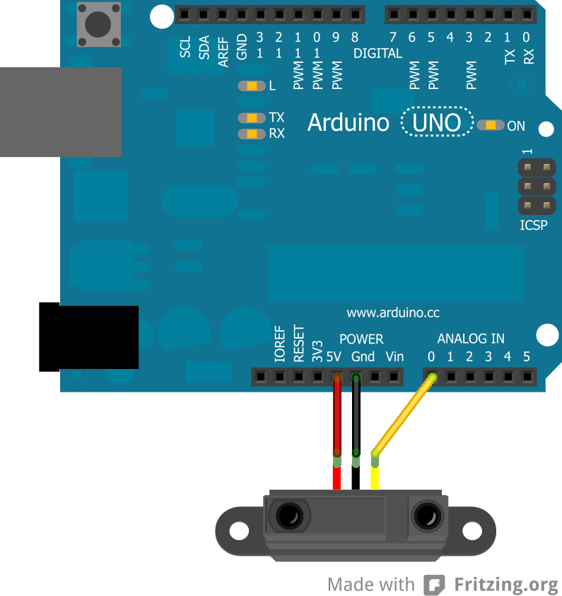
For the GP2Y0D810 sensor, Pololu makes a breakout board that has three pins on it: VIN, GND, and OUT.
Schematic
The important thing to note is that the OUT pin goes to an analog pin.
Coding
This sensor was used on a robot that did not want to get too close to objects, so when the analog value hit a given number that meant that the robot was within 10cm of an object on the side that the sensor faced. Knowing the value, the robot would be able to respond accordingly.
Below is the code explaining how the sensor works. The value that is given was found by holding objects over the sensor and lowering them until the built-in LED would light up. The value was found to be consistent.
int irPin = A0;
int sensorValue = 0;

void setup() {
  Serial.begin(9600);
}

void loop() {
  sensorValue = analogRead(irPin);

  //check for value of 85 or less for distance testing
  if (sensorValue <= 85) {
    Serial.println("Too close");
  }

  delay(1000);
}
This is just a very simple use of the infrared sensor, but an effective one depending on the purpose.
GP2Y0A02YK Infrared Sensor in Real Distance
GP2Y0A02YK Infrared Sensor in Real DistanceIntroduction
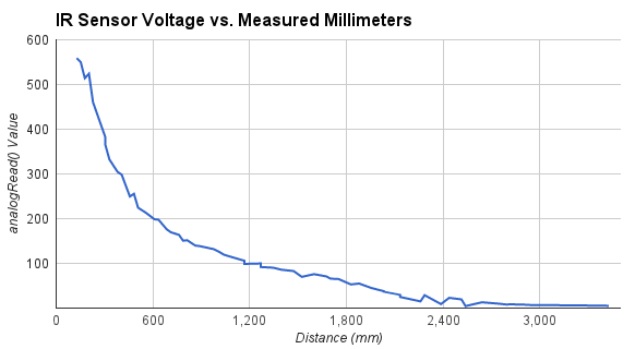
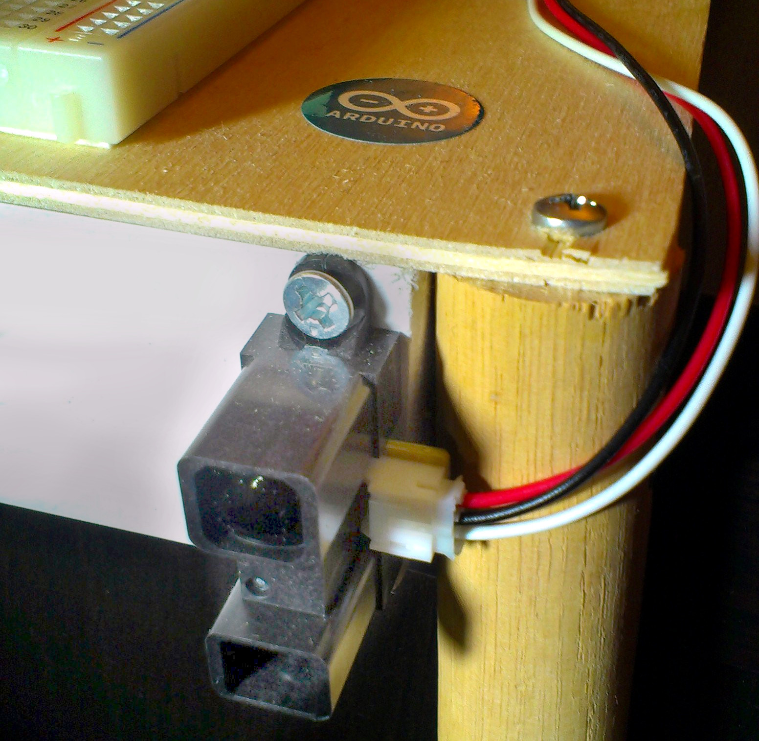 This is a longer range version of the GP2Y0D810 Infrared Sensor. They're about 15$, and work fairly well for distances between 0.5 meters and 1.5 meters. It is important to note that the distance to voltage curve is not linear. So, if you want the real distance, measured in mm, you'll need to come up with a best fit curve based on some experimental data.
Like the midrange version, the wiring is easy. Red goes to +5V, Black goes to GND, and white goes to an analog pin (in my case A0). You can even hook multples of them up as long as you use a seperate white to analog pin.
Again, IR does not the same on all surfaces. It depends on their reflectivity. For example, black surfaces tend to appear to be really far away since they don't bounce back much light. So, when you gather your data to make a best fit curve, you should use a surface similar to the one you plan on detecting.
Collect Some Data
I used 5V input voltage hooked up to an Arduino's analog read pin. I laid down a measuring tape and recorded the output from analogRead() at each distance. Here are the results:
Fit the Data
I think a polynomial regression would best fit the curve. I used a cubic polynomial. Here are the coefficients that I found based on my samples:
-0.00003983993846 v3+ 0.0456899769 v2 - 17.48535575 v + 2571.052715
Convert to Code
Once you have a good fit curve, the code is fairly straightforward:
//some globals used for averaging the samples

int numSamples = 0;
long irSum = 0;

//convert voltage to millimeters
int convertIRvoltsToMM(float v) {
    return -0.00003983993846*v*v*v+ 0.0456899769 *v*v - 17.48535575 * v + 2571.052715;
}


void setup() {}

void loop() {
    irSum += analogRead(A0);
    numSamples++;


    if ( numSamples >= 10 ) {
        int distance = convertIRvoltsToMM( float(irSum) / float(numSamples) );

        Serial.println( distance );
        irSum = numSamples = 0;
    }
}
Conclusion
It may be a good idea to take samples at a somewhat rapid frequency and average them together to produce more accurate results. Even after doing this, mine still fluctuates by a couple of centimeters even in its acurrate range. There is a chance this could be cleaned up with a better electronic circuit though.
You can also hook up two of these, take samples from both of them, and average the two. They do not seem to interfere with each other too much.
The variability of detection with reflection surface colors is also a pretty significant drawback. It is enough of a drawback that if you are really looking to measure anything in real distance, you probably should not use them. They probably work better as "threshold" detectors, where they are triggered once it reaches a certain voltage.
Ping))) Ultrasonic Sensor
Ping))) Ultrasonic SensorIntroduction
Parallax's Ping))) sensor is an ultrasonic sensor that is used for distance measurements.
Ultrasonic sensors work by sending out a sound wave and waiting until that wave bounces back to the sensor. This means that the sensor's accuracy can actually change with the speed of sound. However, this is usually not an issue.
The advantage of the Ping sensor over similar ultrasonic sensors is that it only has three pins: +5V, GND, Trigger. This means that one less pin is used on the Arduino, which may be crucial to a project.
Coding the Ping
Coding the Ping is very simple since there is an Arduino example code included in the IDE under: File >> Examples >> 06.Sensors >> Ping.
This gives the basic code to get it Ping operating. To integrate this into code, it may not be necessary to read the sensor everytime, so putting a timer on it may be advantageous:
long previousMillis = millis();
int PingPin = 7;

void setup() {
  Serial.begin(9600);
}

void loop() {
  int interval = 1000;
  long duration;

  if(millis() - previousMillis > interval) {
    //Ping is triggered
    pinMode(pingPin, OUTPUT);
    digitalWrite(pingPin, LOW);
    delayMicroseconds(2);
    digitalWrite(pingPin, HIGH);
    delayMicroseconds(5);
    digitalWrite(pingPin, LOW);
    pinMode(pingPin, INPUT);
    duration = pulseIn(pingPin, HIGH);

    previousMillis = millis();
  }
}
This is a simple way to trigger the sensor only when the interval of time has passed.
HC-SR04 Ultrasonic Distance Sensor
HC-SR04 Ultrasonic Distance SensorIntroduction
The HC-SR04 distance sensor is an ultrasonic sensor that is used for distance measurements.
Ultrasonic sensors work by sending out a sound wave and waiting until that wave bounces back to the sensor. This means that the sensor's accuracy can actually change with the speed of sound. However, this is usually not an issue.
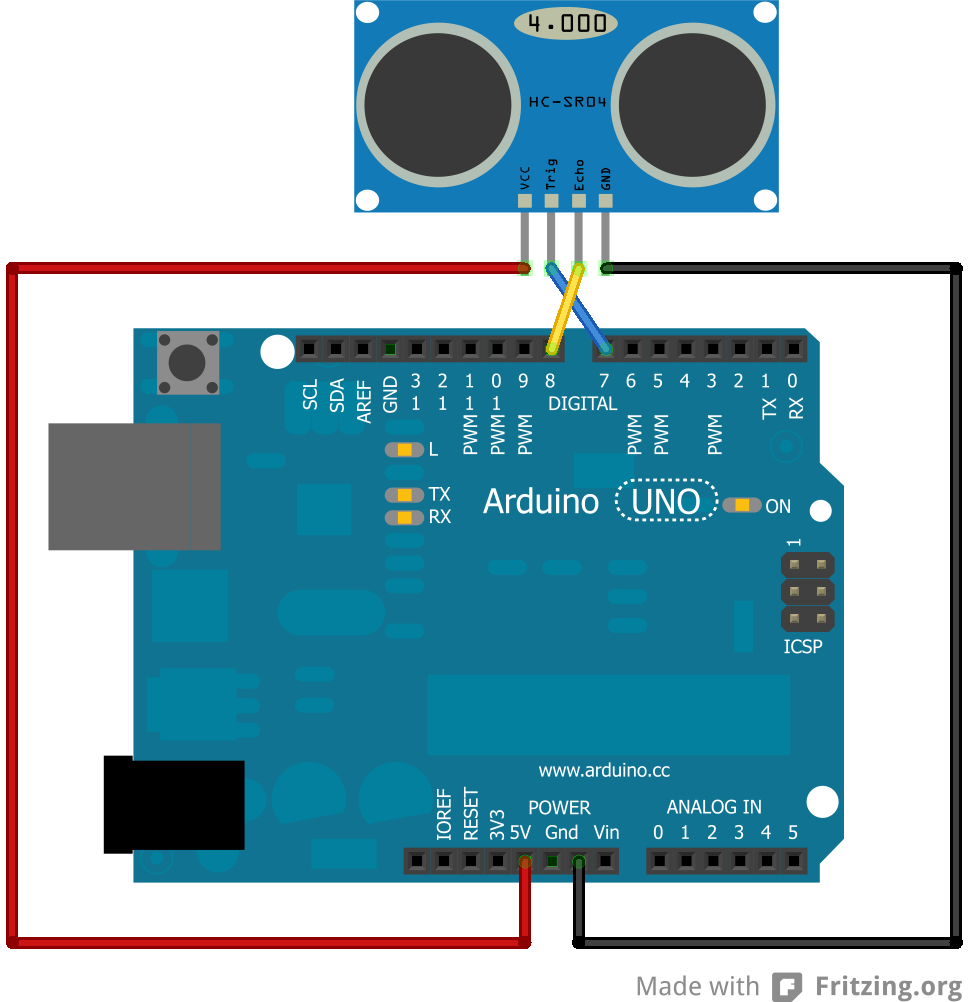
This is a cheaper alternative to the Ping sensor. Instead of three pins, it has four: +5V, GND, Trigger, and Echo. This means that one less pin is available on the Arduino, but, depending on the project, that may not matter.
Schematic
The sensor is connected as follows:
Coding
Coding the HC-SR04 is simple since the pre-existing code for the Ping may quickly be developed to work with it. For example:
//Adapted from David A. Mellis' code for Ping sensor
const int trigPin = 7;
const int echoPin = 8;

void setup() {
  // initialize serial communication:
  Serial.begin(9600);
  pinMode(trigPin,OUTPUT);
  pinMode(echoPin,INPUT);
}

void loop()
{
  long duration, inches, cm;

  digitalWrite(trigPin, LOW);
  delayMicroseconds(2);
  digitalWrite(trigPin, HIGH);
  delayMicroseconds(5);
  digitalWrite(trigPin, LOW);

  duration = pulseIn(echoPin, HIGH);

  // convert the time into a distance
  inches = microsecondsToInches(duration);
  cm = microsecondsToCentimeters(duration);

  Serial.print(inches);
  Serial.print("in, ");
  Serial.print(cm);
  Serial.print("cm");
  Serial.println();

  delay(100);
}

long microsecondsToInches(long microseconds)
{
  // According to Parallax's datasheet for the PING))), there are
  // 73.746 microseconds per inch (i.e. sound travels at 1130 feet per
  // second).  This gives the distance travelled by the ping, outbound
  // and return, so we divide by 2 to get the distance of the obstacle.
  // See: http://www.parallax.com/dl/docs/prod/acc/28015-PING-v1.3.pdf
  return microseconds / 74 / 2;
}

long microsecondsToCentimeters(long microseconds)
{
  // The speed of sound is 340 m/s or 29 microseconds per centimeter.
  // The ping travels out and back, so to find the distance of the
  // object we take half of the distance travelled.
  return microseconds / 29 / 2;
}
This code simply takes into account that the one pin on the Ping is two seperate pins on the HC-SR04 sensor.
PIR Sensor (HC-SR501)
PIR Sensor (HC-SR501)Introduction
Passive Infra-Red (PIR) sensors are used to detect motion based on the infrared heat in the surrounding area. This makes them a popular choice when building a system to detect potential intruders or people in general. These sensors can take for 10-60 seconds to warm up, so try to avoid motion during that time.
Parts
- Arduino
- PIR Sensor
- Wires
Schematic
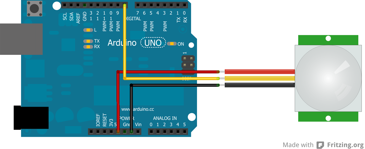
Below is the schematic for using a PIR sensor. It is fairly simple.
Code
Adafruit has a really good tutorial for how these sensors are used and various projects for them.
Below is the code for working with a PIR sensor. It should be noted that the PIR sensor does not respond immediately when motion stops. This has to do with the two potentiameters on the sensor.
int pirPin = 8;
int val;

void setup() {
  Serial.begin(9600);
}

void loop() {
  val = digitalRead(pirPin); //read state of the PIR

  if (val == LOW) {
    Serial.println("No motion"); //if the value read is low, there was no motion
  }
  else {
    Serial.println("Motion!"); //if the value read was high, there was motion
  }

  delay(1000);
}Linksprite JPEG Camera
Linksprite JPEG CameraIntroduction
Cameras can be used in numerous applications: survellience, hobbies, robotics, etc. They are very useful to see what is happening when a robot is moving on its own or even to just have fun with.
I got a UART camera to play around with and that I intend to stick on a robot. However, getting the code functioning on the camera was more difficult than I initially expected and there did not appear to be any good tutorials available.
I modified the code provided by Linksprite for their camera so that it will continuously take pictures rather than take one and stop. After all, if this camera is going to be used on a robot, it should be able to take more than one picture.
Adafruit and Sparkfun both provide sample code, but they required having an SD card, which I did not have at the time. This will print the images directly to the serial port and then the images can be translated with the Python code.
Parts
- TTL JPEG Camera from Linksprite
- Arduino
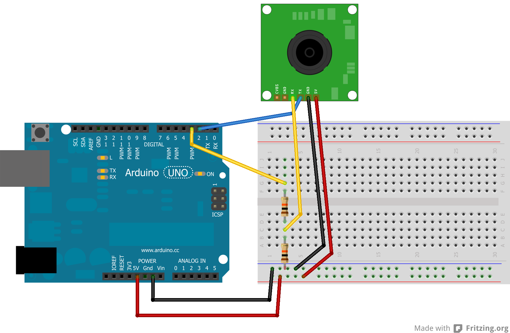
- 2 10K resistors
- Wires
Schematic
Below is the schematic for how to hook up the camera (Adafruit had a tutorial explaining this):
Code
There are two steps in getting a picture from the camera. The first is being able to get the proper HEX to print out on the Arduino serial monitor. The second is being able to turn all that HEX into a JPEG image.
Arduino: Take Pictures
The following code was made by altering the code provided by Linksprite to allow the camera to continuously take images. The original code took one image and stopped.
#include <SoftwareSerial.h>

byte incomingbyte;

//Configure pin 2 and 3 as soft serial port
SoftwareSerial cameraSerial = SoftwareSerial(2, 3);

int a=0x0000,  //Read Starting address
    j=0,
    k=0,
    count=0;
uint8_t MH,ML;
boolean EndFlag=0;


void setup() {
  Serial.begin(19200);
  cameraSerial.begin(38400);

  SendResetCmd();
  delay(3000);
}

void loop() {
  SendTakePhotoCmd();

  Serial.println("Start pic");
  delay(100);

  while(cameraSerial.available()>0) {
    incomingbyte=cameraSerial.read();
  }
  byte b[32];

  while(!EndFlag) {
    j=0;
    k=0;
    count=0;
    SendReadDataCmd();

    delay(75); //try going up
    while(cameraSerial.available()>0) {
      incomingbyte=cameraSerial.read();
      k++;
      if((k>5)&&(j<32)&&(!EndFlag)) {
        b[j]=incomingbyte;
        if((b[j-1]==0xFF)&&(b[j]==0xD9))
        EndFlag=1;
        j++;
        count++;
      }
    }

    for(j=0;j<count;j++) {
      if(b[j]<0x10)
        Serial.print("0");
      Serial.print(b[j], HEX);
    }
    Serial.println();
  }

  delay(3000);
  StopTakePhotoCmd(); //stop this picture so another one can be taken
  EndFlag = 0; //reset flag to allow another picture to be read
  Serial.println("End of pic");
  Serial.println();
}

//Send Reset command
void SendResetCmd() {
  cameraSerial.write((byte)0x56);
  cameraSerial.write((byte)0x00);
  cameraSerial.write((byte)0x26);
  cameraSerial.write((byte)0x00);
}

//Send take picture command
void SendTakePhotoCmd() {
  cameraSerial.write((byte)0x56);
  cameraSerial.write((byte)0x00);
  cameraSerial.write((byte)0x36);
  cameraSerial.write((byte)0x01);
  cameraSerial.write((byte)0x00);

  a = 0x0000; //reset so that another picture can taken
}

void FrameSize() {
  cameraSerial.write((byte)0x56);
  cameraSerial.write((byte)0x00);
  cameraSerial.write((byte)0x34);
  cameraSerial.write((byte)0x01);
  cameraSerial.write((byte)0x00);
}

//Read data
void SendReadDataCmd() {
  MH=a/0x100;
  ML=a%0x100;

  cameraSerial.write((byte)0x56);
  cameraSerial.write((byte)0x00);
  cameraSerial.write((byte)0x32);
  cameraSerial.write((byte)0x0c);
  cameraSerial.write((byte)0x00);
  cameraSerial.write((byte)0x0a);
  cameraSerial.write((byte)0x00);
  cameraSerial.write((byte)0x00);
  cameraSerial.write((byte)MH);
  cameraSerial.write((byte)ML);
  cameraSerial.write((byte)0x00);
  cameraSerial.write((byte)0x00);
  cameraSerial.write((byte)0x00);
  cameraSerial.write((byte)0x20);
  cameraSerial.write((byte)0x00);
  cameraSerial.write((byte)0x0a);

  a+=0x20;
}

void StopTakePhotoCmd() {
  cameraSerial.write((byte)0x56);
  cameraSerial.write((byte)0x00);
  cameraSerial.write((byte)0x36);
  cameraSerial.write((byte)0x01);
  cameraSerial.write((byte)0x03);
}
Arduino: Change Image Size
Here is code that I use when I want to alter the size of the images being taken.
/***********************
ChangeCameraSize
Jennifer Case
2/28/2013
***********************/

#include <SoftwareSerial.h>

SoftwareSerial mySerial = SoftwareSerial(2, 3);

void setup()
{
  Serial.begin(19200);
  mySerial.begin(38400);

}

int sizeChange = 0;

void loop() {
  SendResetCmd();
  delay(3000);

  if (sizeChange==0) {
    ChangeSizeSmall();
    Serial.println("Size Changed");
    sizeChange++;
  }

}

//Send Reset command
void SendResetCmd() {
  mySerial.write((byte)0x56);
  mySerial.write((byte)0x00);
  mySerial.write((byte)0x26);
  mySerial.write((byte)0x00);
}

void ChangeSizeSmall() {
    mySerial.write((byte)0x56);
    mySerial.write((byte)0x00);
    mySerial.write((byte)0x31);
    mySerial.write((byte)0x05);
    mySerial.write((byte)0x04);
    mySerial.write((byte)0x01);
    mySerial.write((byte)0x00);
    mySerial.write((byte)0x19);
    mySerial.write((byte)0x22);
}

void ChangeSizeMedium()
{
    mySerial.write((byte)0x56);
    mySerial.write((byte)0x00);
    mySerial.write((byte)0x31);
    mySerial.write((byte)0x05);
    mySerial.write((byte)0x04);
    mySerial.write((byte)0x01);
    mySerial.write((byte)0x00);
    mySerial.write((byte)0x19);
    mySerial.write((byte)0x11);
}

void ChangeSizeBig()
{
    mySerial.write((byte)0x56);
    mySerial.write((byte)0x00);
    mySerial.write((byte)0x31);
    mySerial.write((byte)0x05);
    mySerial.write((byte)0x04);
    mySerial.write((byte)0x01);
    mySerial.write((byte)0x00);
    mySerial.write((byte)0x19);
    mySerial.write((byte)0x00);
}
I just alter which function I want to call to change the size.
Python
The following code takes a text file named "outputData.txt" and turns it into an JPEG image called "binaryData.jpg". The Python code should be in the same folder that the images are in or it will not be able to find it.
The following is code for Python 2.7:
import binascii

f = open ("outputData5.txt","r")
nf = open("binaryData5.jpg","wb")

#Read whole file into data
while 1:
    c = f.readline()
    d = c.strip()
    if not c:
        break
    nf.write(binascii.a2b_hex(d))


# Close the file
f.close()
nf.close()
The following is code for Python 3:
import binascii

f = open ("outputData14.txt","r")
nf = open("binaryData14.jpg","wb")

#Read whole file into data
while 1:
    c = f.readline()
    d = c.strip()
    if not c:
        break
    nf.write(binascii.a2b_hex(bytes(d, "ascii")))


# Close the file
f.close()
nf.close()
Troubleshooting
There are many errors that can occur when dealing with the camera. I've listed the ones that seem to be common problems and that I've run into.
Banding or Artifacting
I found that banding or artifacting occurred when I tried to take larger images. There is a delay right after the SendReadDataCmd() line that can be increased to reduce banding, but I was never successfully able to take the large images without either banding or losing the last part of the image.
Python JPEG did not work
If the JPEG made from the text file did not open or was corrupted, it is probably due to the fact that the text file did not have the complete image. This could be due to the first line missing from image sent through the serial.
This has been fixed by adding a small delay after the command for the taking the photo has been sent.
Edits
12/19/2013:
Edits have been made to the code so that more than one picture will be read. - Thanks jadnexus for pointing it out
Also if you are looking to save these pictures onto an SD card, take a look at this following tutorial: http://robotic-controls.com/learn/projects/simple-security-system or http://robotic-controls.com/learn/sensors/linksprite-jpeg-camera/saving-images-sd-card-0
Saving Images on an SD Card
Saving Images on an SD CardIntroduction
Before trying this code, make sure you have ensured that your camera works because you will not be able to see what is happening with the camera while it is saving to the SD card. If you are having issues with this, please check out the Evaluation Software provided by Linksprite.
You should also take a look at this tutorial and ensure that you can in fact get a converted images before trying to save several images.
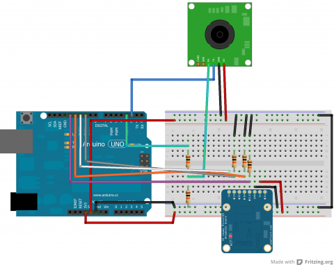
Parts
- TTL Camera by Linksprite
- SD Card Breakout Board
- SD Card
- 2 10k Resistors
- 3 other Resistors (I'm not sure if size matters, but mine were all above 1k)
- Wires
- Arduino
Schematic
Code
Arduino
This code sets up the SD card and takes pictures, incrementing the name the file is saved as each time.
/***************************
Save Images on SD Card

by Jennifer Case
4/14/2014

Parts:
-SD Card Breakout Board
-TTL Camera

Pin 2,3 - Camera
Pin 10 - CS/D3
Pin 11 - CMD
Pin 12 - D0
Pin 13 - CLK
****************************/
#include <SoftwareSerial.h>
#include <SdFat.h>

//SD Card
SdFat sd;
SdFile myFile;
int picCnt = 0;

//Camera
byte incomingbyte;
SoftwareSerial cameraSerial = SoftwareSerial(2, 3);   //Configure pin 2 and 3 as soft serial port
int a=0x0000,j=0,k=0,count=0;   //Read Starting address
uint8_t MH,ML;
boolean EndFlag=0;

//Declare pins
const int chipSelect = 10;

void setup() {
  Serial.begin(19200); //start serial
  cameraSerial.begin(38400); //start serial with camera

  // Initialize SdFat or print a detailed error message and halt
  // Use half speed like the native library.
  // change to SPI_FULL_SPEED for more performance.
  if (!sd.begin(chipSelect, SPI_HALF_SPEED)) sd.initErrorHalt();

  SendResetCmd(); //allows camera to take pictures
  delay(3000); //delay necessary for camera reset
}

void loop() {
    //create title for images
    char photoTitle[25] = {};
    sprintf(photoTitle, "pic%d.txt", picCnt);

    //make sure file can be created, otherwise print error
    if (!myFile.open(photoTitle, O_RDWR | O_CREAT | O_AT_END)) {
      sd.errorHalt("opening photoTitle.txt for write failed");
    }

    SendTakePhotoCmd(); //take photo
    delay(200); //delay to make sure there is no drop in the data

    while(cameraSerial.available()>0) {
      incomingbyte=cameraSerial.read(); //clear unneccessary serial from camera
    }
    byte b[32];

    while(!EndFlag) {
      j=0;
      k=0;
      count=0;
      SendReadDataCmd(); //command to get picture from camera

      delay(75); //delay necessary for data not to be lost
      while(cameraSerial.available()>0) {
        incomingbyte=cameraSerial.read(); //read serial from camera
        k++;
        if((k>5)&&(j<32)&&(!EndFlag)) {
          b[j]=incomingbyte;
          if((b[j-1]==0xFF)&&(b[j]==0xD9))
          EndFlag=1; //when end of picture appears, stop reading data
          j++;
          count++;
        }
      }

      for(j=0;j<count;j++) { //store picture into file
        if(b[j]<0x10)
          myFile.print("0");
        myFile.print(b[j], HEX);
      }
      myFile.println();
    }

    StopTakePhotoCmd(); //stop this picture so another one can be taken
    EndFlag = 0; // reset flag to allow another picture to be read

    myFile.close(); //close file

    picCnt++; //increment value for next picture
}

//Send Reset command
void SendResetCmd() {
  cameraSerial.write((byte)0x56);
  cameraSerial.write((byte)0x00);
  cameraSerial.write((byte)0x26);
  cameraSerial.write((byte)0x00);
}

//Send take picture command
void SendTakePhotoCmd() {
  cameraSerial.write((byte)0x56);
  cameraSerial.write((byte)0x00);
  cameraSerial.write((byte)0x36);
  cameraSerial.write((byte)0x01);
  cameraSerial.write((byte)0x00);

  a = 0x0000; //reset so that another picture can taken
}

void FrameSize() {
  cameraSerial.write((byte)0x56);
  cameraSerial.write((byte)0x00);
  cameraSerial.write((byte)0x34);
  cameraSerial.write((byte)0x01);
  cameraSerial.write((byte)0x00);
}

//Read data
void SendReadDataCmd() {
  MH=a/0x100;
  ML=a%0x100;

  cameraSerial.write((byte)0x56);
  cameraSerial.write((byte)0x00);
  cameraSerial.write((byte)0x32);
  cameraSerial.write((byte)0x0c);
  cameraSerial.write((byte)0x00);
  cameraSerial.write((byte)0x0a);
  cameraSerial.write((byte)0x00);
  cameraSerial.write((byte)0x00);
  cameraSerial.write((byte)MH);
  cameraSerial.write((byte)ML);
  cameraSerial.write((byte)0x00);
  cameraSerial.write((byte)0x00);
  cameraSerial.write((byte)0x00);
  cameraSerial.write((byte)0x20);
  cameraSerial.write((byte)0x00);
  cameraSerial.write((byte)0x0a);

  a+=0x20;
}

void StopTakePhotoCmd() {
  cameraSerial.write((byte)0x56);
  cameraSerial.write((byte)0x00);
  cameraSerial.write((byte)0x36);
  cameraSerial.write((byte)0x01);
  cameraSerial.write((byte)0x03);
}
Python
The Python code from the camera tutorial has been revamped to allow for multiple photos to be processed at a time. This is set up to work with the naming given in the above code. The user may still have to adjust the range depending on the number of photos.
#!/usr/bin/python
# open file
import binascii

count = 0

for count in range (0,4):

    f = open ("PIC%d.txt" % (count),"r")
    nf = open("IMAGE%d.jpg" % (count),"wb")

    #Read whole file into data
    while 1:
        c = f.readline()
        d = c.strip()
        #print (c)
        #print (d)
        if not c:
            break
        nf.write(binascii.a2b_hex(bytes(d, "ascii")))


    # Close the file
    f.close()
    nf.close()
Adafruit Ultimate GPS Breakout
Adafruit Ultimate GPS BreakoutIntroduction
The Adafruit Ultimate GPS Breakout board is an excellent way to get started with GPS and Arduino. Adafruit does an excellent job providing tutorials and code for the user. I would suggest checking out their provided tutorials and code before looking elsewhere.
When I was working with the GPS, I made a few changes to the code that Adafruit provided based on how the Arduino handles floats (or doesn't handle them). The changes that I made are not particularly necessary depending on what it is being used for, but does increase the accuracy of the module on the code level. However, I suggest that you become familiar with how the unit works first before attempting to alter the code.
Schematic
Below is a schematic for connecting the GPS module to the Arduino.
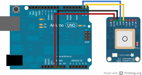
There are several pins on the breakout board that are unused in this schematic. These other pins are not necessary for communication to the GPS module, but may be useful in other respects.
How to Read Latitude and Longitude from Output
Adafruit has provided a number of different codes for a variety of applications. Specifically, I am going to go over the parsing code they provide and how to read the data for latititude and longitude. Below is the portion of the code that deals with the latitude and longitude data.
// Test code for Adafruit GPS modules using MTK3329/MTK3339 driver
//
// This code shows how to listen to the GPS module in an interrupt
// which allows the program to have more 'freedom' - just parse
// when a new NMEA sentence is available! Then access data when
// desired.
//
// Tested and works great with the Adafruit Ultimate GPS module
// using MTK33x9 chipset
//    ------> http://www.adafruit.com/products/746
// Pick one up today at the Adafruit electronics shop
// and help support open source hardware & software! -ada

Serial.print("Location: ");
Serial.print(GPS.latitude, 4); Serial.print(GPS.lat);
Serial.print(", ");
Serial.print(GPS.longitude, 4); Serial.println(GPS.lon);
This code uses the libraries that Adafruit has made available where they parse the data for the user. Here, you can see that GPS.latitude will call the float holding the latitude for the user (GPS being an instance of the Adafruit_GPS class and GPS.latitude being a property of the class). While GPS.lat will get you either 'N' or 'S' depending on the hemisphere.
Translating GPS Data
Here we need to analyze the actual output more closely. The sample output that we will be working with is a latitude reading of 1234.5678 and a longitude reading of 12345.6789.
If latitude reading = 1234.5678, then the actual latitude is read as 12° 34.5678'.
If longitude reading = 12345.6789, then the actual longitude is read as 123º 45.6789'.
This means that the floats can require some processing depending on what data is needed. Personally, I prefer turning all the data into minutes of degrees.
Thus, 12° 34.5678' = 12*60 + 34.5678 = 754.5678' and 123º 45.6789' = 123*60 + 45.6789 = 7425.6789'.
This can then be converted into meters knowing that 1' ≈ 1852 meters (going off of the fact that each degree is approximately 111km).
With this knowledge, we can take two latitude and two longitude readings and determine the difference is meters between the two coordinates. I show how to do this in a tutorial on Making a Map (pending).
Problem with Floats
If you look in the library provided by Adafruit, you will see that the data is parsed as follows (this is only a small portion of the entire code):
/***********************************
This is our GPS library

Adafruit invests time and resources providing this open source code,
please support Adafruit and open-source hardware by purchasing
products from Adafruit!

Written by Limor Fried/Ladyada for Adafruit Industries.
BSD license, check license.txt for more information
All text above must be included in any redistribution
****************************************/

// parse out latitude
p = strchr(p, ',')+1;
latitude = atof(p);

p = strchr(p, ',')+1;
if (p[0] == 'N') lat = 'N';
else if (p[0] == 'S') lat = 'S';
else if (p[0] == ',') lat = 0;
else return false;

// parse out longitude
p = strchr(p, ',')+1;
longitude = atof(p);

p = strchr(p, ',')+1;
if (p[0] == 'W') lon = 'W';
else if (p[0] == 'E') lon = 'E';
else if (p[0] == ',') lon = 0;
else return false;
All the data starts off as a string and is parsed according to what the data actually is. Here, you can see that the string containing the latitude and longitude are turned into floats with the atof(p) command.
What I have found is that Arduino was not made to handle floats well (and doubles are not different than floats to the Arduino). Arduino floats are really only accurate up to seven digits while the GPS floats have up to eight or nine digits. So, what the Arduino does is given seven accurate digits and then guesses on the other two. Below is a picture of an experiment where the string from the GPS is printed followed by the atof(p) float that the original code is producing.
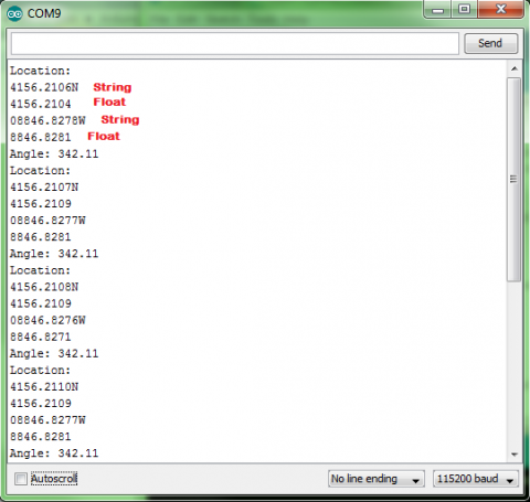
Looking at this data, you can see that the difference between the true string value and the float estimate is as large as 0.0005, which may not seem like much, but this can translate to approximately 0.926 meters (using the math from above), which could have an effect on the accuracy of the GPS. Although, admittedly, this may not be a large enough difference to matter and the approximation of meters to degrees will probably not be accurate enough to warrant the 0.926m difference. My suggestion would be to skip the rest of the tutorial if this does not matter. However, if this does matter, there is a work around to get the string values.
Altering the Library
To fix the problem, I introduce new variables to hold the latitude and longitude into the header file. This variable is a character array. Below is the line added to the header file:
char latit[10], longit[11]; //added to get strings for latitude and longitude
The code the was displayed before is then altered to look like the following:
/***********************************
This is our GPS library

Adafruit invests time and resources providing this open source code,
please support Adafruit and open-source hardware by purchasing
products from Adafruit!

Written by Limor Fried/Ladyada for Adafruit Industries.
BSD license, check license.txt for more information
All text above must be included in any redistribution

Alterations by Jennifer Case
****************************************/

// parse out latitude
p = strchr(p, ',')+1;
for(int i=0;i<9;i++) {
  latit[i] = p[i];
}
latit[9] = '\0';
latitude = atof(p);

p = strchr(p, ',')+1;
if (p[0] == 'N') lat = 'N';
else if (p[0] == 'S') lat = 'S';
else if (p[0] == ',') lat = 0;
else return false;

// parse out longitude
p = strchr(p, ',')+1;
for(int i=0;i<10;i++) {
  longit[i] = p[i];
}
longit[10] = '\0';
longitude = atof(p);
The new variables, latit and longit, can then be called similar to how the example parsing code called latitude and longitude previously. The only difference being that latit and longit are treated as strings rather than floats.
Because these coordinates are now strings, that can complicate the processing of them, so I have made a Coordinate class to handle the strings and distribute them in a more controlled manner.
Coordinate Library
The coordinate library has been developed to work with the strings that will get parsed out with these modifications to the Adafruit library. I have attached the library to this tutorial.
There are uses in this library that will not be necessary to use (such as a few constuctors). Some of them have been made to function with the construction of a map.
The main constructor that will be of interest is the following:
//constructs latitude and longitude from GPS string
//degreeLen is determined by whether you are constructing
//a latitude or a longitude. Use a degreeLen of 2 when
//constructing a latitude and a degreeLen of 3 when
//constructing a longitude.
Coordinate::Coordinate(char* gpsString, int degreeLen) {
  int i=0;
  char degree[4];
  char minute[3];
  char minflt[7];

  //Process string
  int j;
  for(j=0;j<degreeLen;j++) {
    degree[j] = gpsString[i];
    i++;
  }
  degree[j] = '\0';

  for(j=0;j<2;j++) {
    minute[j] = gpsString[i];
    i++;
  }
  minute[j] = '\0';

  minflt[0]='0';
  for(j=1;j<6;j++) {
    minflt[j]=gpsString[i];
    i++;
  }
  minflt[j] = '\0';

  //calculate for and aft
  fore = 60*atol(degree) + atol(minute);
  aft = atof(minflt); //atof is acceptable because of reduced digits
}
This method takes two arguments, a string and an integer. The string is latit or longit from the previous code. The integer lets the class know whether to process the string as a latitude or longitude. As stated previously, longitudes have one extra digit in the degree portion. So while the degree portion of a latitude is two digits long (degreeLen = 2), the degree portion of a longitude is three digits long (degreeLen = 3).
This converts everything into minutes for the user and manages it in two sections a fore part and an aft. The fore portion is the whole minutes while the aft part is the decimal parts of the minutes.
For communication purposes, there is also a method that allows printing a coordinate through the Arduino's serial:
//convert coordinate to a string and print through serial
void Coordinate::print() {
  char strFore[10], strAft[7], tempAft[6];

  dtostrf(aft,7,4,strAft);

  int i = 0;
  for(i=0;i<6;i++) {
    tempAft[i] = strAft[i+2];
  }
  tempAft[i] = '\0';

  sprintf(strFore, "%02d", fore);
  Serial.print(strFore); //this serial can be changed if using a mega or soft serial
  Serial.print(tempAft); //this serial can be changed if using a mega or soft serial
}
There are more methods that can be used as well or added to the library to fit individual needs.
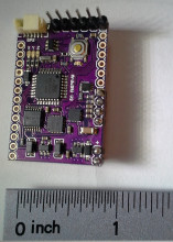
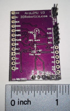
ArduIMU
ArduIMUIntroduction
An IMU is something used to detect primarily orientation, but is a general term for an Inertial Measurement Unit. Needless to say, they can provide some vital information for mobile robots. In particular, flying robots need them since there is no way to guess orientation using wheel encoders.
An advantage to having an all-in-one unit instead of just using each of its sensors yourself is that the board can cross-check and merge the data for you. For example, a gyro gives you changes in orientation in each axis, but an accelerometer and magnetometer both send 3D directions - both in different directions too. Furhtermore, the acceleration doesn't even always point down.
One would hope that these sensors would be able to give velocity or even position information. Sadly, the sensors are just not accurate enough to be able to numerically integrate and avoid drift error. It can be possible to use the information to refine something that is capable of giving position information - like a GPS. That is partly why many of these boards include a GPS port. The other is that they are primarily used in flying drones, which usually want a GPS anyway and it is not too expensive to add the connector.
Advantages
While maybe not the highest performance IMU, I picked this sensor because I found it reasonably cheap for $50 at DIY Robotics. I am now wondering if that was an error, since it is now more expensive. For $80, it is still an ok sensor. I also appreciate the fact that it can be reprogrammed with an FTDI cable and the Arduino IDE. This allows you to change settings and add your own features. Other IMU sensors will do this too, though. A very similar is the 130$ Razor IMU available from SparkFun.
Communication
Connection
Simply connect the RX to TX and TX to RX on each end of the ArduIMU and whatever you're reading it with.
To just read the output on a linux based controller, simply run the command in bash:
sudo cat /dev/ttyAMA0
Do not use I2C
Do not bother with trying to communicate with it via i2c. Sure, i2c is nice and compact, but the compass on the board is actually using those pins and i2c. As a result, the ArduIMU is in master mode, and you cannot be the master. I wasted a lot of time trying to figure out how to read it. Do not be fooled by the fact that you can see a device on the 1E address, that is the compass. Furthermore, i2c is a little too slow to be used, so even if that wasn't a problem, it would still be a bad idea.
Format
According to the Google Code page, the output format is like this:
!!!VER:1.8.1,RLL:1.12,PCH:-0.07,YAW:34.03,IMUH:253,LAT:499247361,LON:-1193955623, ALT:3525,COG:0,SOG:0,FIX:1,SAT:9,TOW:21230400***
That's probably not what yours looks like though. To see where this comes from, find the source code here for your version, then look at Output.pde. In my version 1.9.1, the format adds slots for analog pins. My ArduIMU v3 outputs something in the format of:
Temp: 63503 Accels: 0 2 27 Gyros: 0 0 0 Mag: 397 0 -482
First of all, those spaces are actually tab characters. Also I have no idea what temp is doing, but it looks useless here since it is just changing randomly. "Gyros" is the change in orientation detected by the gyroscope. So it will say 1 or -1 usually in each - maybe a little more if it's turning fast. The accels and mag outputs are vectors pointing in the direction and magnitude of the pull in x,y, and z. The default output lacks any euler angles, quaternions, or direction cosine matrices which is disappointing.
In all likelihood, the ArduIMU is probably sending you more information than you really want. It may be worthwhile to reprogram it to give you only the information you need. Most of the common choices can be made by editing Arduimu.ino.
After some tweaking, mine now looks like this:
RLL:-7.76,PCH:3.77,YAW:145.72,IMUH:253,ACCX:-0.33,ACCY:-0.67,ACCZ:9.58,
It prints the euler angles, IMU health, and acceleration vector. I also removed anything to do with a GPS. It's fast enough that the Arduino IDE can't keep up with the serial output. It maxes out my processor and lags behind a bit. Hopefully this is not the sensor lagging, but just the extremely rapid displaying.
If you are interested, read how to program the ArduIMU below, then grab my modifications to the stock ArduIMU code at the bottom of this page.
Reprogramming
Wiring the FTDI
| ArduIMU v3 | OSEPP FTDI |
| BLK | GND |
| GND | CTS |
| 5V | VCC |
| RX | TXD |
| TX | RXD |
| ??? | DTR |
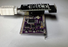
Odds are you really want the Euler angles, quaternion, or rotation matrix to be printed, since that is a lot easier to use quickly. You will need an FTDI cable. I picked the OSEPP one because it has a jumper to choose between 3.3V and 5V, which seems like an awesome feature. I picked that up for around 15$ on Amazon.
I was able to just solder some female header onto my OSEPP FTDI and plug the Arduimu in directly using the group of horizontal pins at the bottom. Also be sure to switch it to 3.3V mode. From what I've read, it seems like it may not matter, really, what the voltage is on some of the lines. SparkFun discuses it on one of their product pages. I'm betting there is some truth to that since there is a 5V pin.
Also, depending on the FTDI cable you have, there is a possibility that you might need to press the reset button yourself. The auto-reset feature is apparently somewhat new and will also depend on whether it is wired up correctly.
It is also recommended that you power the ArduIMU with something other than the FTDI cable while programming. So, be sure to connect an additional power source to the Vin or 3.3V pins.
Makefile
From there, you just need to configure the makefile. Run make configure to configure make, then run make upload to compile and upload it. My Makefile looked like this, but I never actually got it to work:
BOARD	=	atmega328
ARDUINO_DIR  = /usr/share/arduino
TARGET = Arduimu
ARDUINO_PORT = /dev/ttyUSB0
ARDUINO_DIR  = /usr/share/arduino
AVR_TOOLS_PATH = /usr/bin
include ../AP_Common/Arduino.mk
I also found that you might need to add #define ARDUINO 103 to the code in order to fix a few compile errors. This was probably a sign of some bigger problems though.
Arduino IDE
It is actually easier to just use the Arduino IDE.
Copy the Library folder from the zip of the code you download to your sketchbook Library folder.
Open the Arduimu.ino file in the Arduino IDE.
Simply select the correct Serial port - on my Ubuntu Linux system it was /dev/ttyUSB0. Then select a compatible board - the Arduino Nano w ATmega328. The programmer is just the standard AVRISP mkII due to the serial interface selected. On windows, the setup process for the FTDI cable may be more in depth. The ArduIMU google code page has some more information on it. You might be better off just looking up your specific FTDI cable first though.
With the FTDI cable on my system, you can actually just open the serial monitor and set the baud rate to 38400. I didn't know that at first and was hooking it up to a raspberry pi to see the output. This is a lot easier.
Fixing Bugs
If you get this error:
AP_Common/AP_Common.h: In function ‘int strcasecmp_P(const char*, const prog_char_t*)’:
AP_Common/AP_Common.h:108:38: error: ISO C++ forbids declaration of ‘type name’ with no type [-fpermissive]
AP_Common/AP_Common.h:108:38: error: ISO C++ forbids declaration of ‘type name’ with no type [-fpermissive]
AP_Common/AP_Common.h:108:32: error: expected primary-expression before ‘const’
AP_Common/AP_Common.h:108:32: error: expected ‘)’ before ‘const’
Just add this line to the top of Arduimu.pde. Somewhere above the #include statements:
typedef char PROGMEM prog_char;
I also went around and removed FastSerial and just left it with the regular serial. I'm guessing there was a good reason for making their own, but it was extremely annoying that they had to use the same variable name as the regular Serial object. I couldn't get it to compile due to it.
Configuring Output
There are a bunch of #define statements in the Arduimu.ino file. Those can be changed to modify a lot of the important features. I had to change just about every one of the settings to get what I wanted. This is the result:
// Enable Air Start uses Remove Before Fly flag - connection to pin 6 on ArduPilot
#define ENABLE_AIR_START 0  //  1 if using airstart/groundstart signaling, 0 if not
#define GROUNDSTART_PIN 8    //  Pin number used for ground start signal (recommend 10 on v1 and 8 on v2 hardware)

/*Min Speed Filter for Yaw drift Correction*/
#define SPEEDFILT 0 // >1 use min speed filter for yaw drift cancellation (m/s), 0=do not use speed filter

/*For debugging propurses*/
#define PRINT_DEBUG 0   //Will print Debug messages

//OUTPUTMODE=1 will print the corrected data, 0 will print uncorrected data of the gyros (with drift), 2 will print accelerometer only data
#define OUTPUTMODE 1

#define PRINT_DCM 0     //Will print the whole direction cosine matrix
#define PRINT_ANALOGS 0 //Will print the analog raw data
#define PRINT_EULER 1   //Will print the Euler angles Roll, Pitch and Yaw
#define PRINT_GPS 0     //Will print GPS data
#define PRINT_MAGNETOMETER 0     //Will print Magnetometer data (if magnetometer is enabled)

// *** NOTE!   To use ArduIMU with ArduPilot you must select binary output messages (change to 1 here)
#define PRINT_BINARY 0  //Will print binary message and suppress ASCII messages (above)

// *** NOTE!   Performance reporting is only supported for Ublox.  Set to 0 for others
#define PERFORMANCE_REPORTING 0  //Will include performance reports in the binary output ~ 1/2 min
Furthermore, I think it is weird that they would have an option to print the magnetometer, but not the accelerometer. It seems like acceleration would be a lot more important for a controller, since the magnetometer's information, I assume, is already built into the orientation output.
Modifying the Output
To add the acceleration information, I just modified Output.ino (line 61 to 68)
#define ACCELCONVERSION 0.0023147712
Serial.print("ACCX:");
Serial.print(Accel_Vector[0]*ACCELCONVERSION);
Serial.print(",ACCY:");
Serial.print(Accel_Vector[1]*ACCELCONVERSION);
Serial.print(",ACCZ:");
Serial.print(Accel_Vector[2]*ACCELCONVERSION);
Serial.print(",");
The ACCELCONVERSION constant was chosen by expermentation to convert to the output to m/s2 using the following method:
- Print the values of the Accel_Vector
- Leave the ArduIMU on a flat level surface
- Take a few samples of the acceleration on the z axis (Accel_Vector[2])
- ACCELCONVERSION = 9.81 / SampleAverage
Repeat the process, if necessary, until the output is correctly calibrated to the known gravitational constant.
It is perhaps better practice to instead do the conversion on the recieving device, since the values would be more compact and accurately sent over serial. On the other hand, it makes the ArduIMU more easily accessible if the units are known. To convert the acceleration data on the reading device, the proceedure is the same.
Parsing the Serial Input
While you could read this sensor with an Arduino, it already is an Arduino. Furthermore, the mere fact that you're using it probably means you want to analyze a 3D system. You're probably going to need some more firepower. Something like a Raspberry Pi, or a BeagleBone. A Raspberry Pi processor is at least 1000 times faster than an Arduino, and a BeagleBone Black is at least twice as fast as a Raspberry Pi and has more pins.
With these faster devices, you get to use a higher level programming language like Python or Node.js. Both will run Python, so it is a good choice for speed and portability.
Joystick
JoystickIntroduction
Joysticks have become a common tool among various devices, such as gaming controllers. They can be an interesting addition to projects as well. Joysticks are fairly simply components that use two potentiameters to give the readings from two axes. They may also include a button to see if the user has clicked the joystick.
Schematic
Below is a schematic showing how the joystick connects to an Arduino.
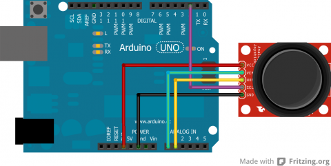
As stated previously, a common joystick will use two rotating potentiameters and a button. The potentiameters are analog while the button is digital.
Code
The following code shows how to read the various components of the joystick.
int verPin = A0;
int horPin = A1;
int selPin = 2;

void setup() {
  pinMode(selPin, INPUT);
  digitalWrite(selPin, HIGH);
}

void loop() {
  int verPos = analogRead(verPin);
  int horPos = analogRead(horPin);
  boolean selBtn = digitalRead(selPin);
}
Getting the information from the component is really simple, but a lot of fun projects can be done with joysticks.
