XBee Configuration
XBee ConfigurationIntroduction
 XBees are one form of wireless communication. They use radio frequency to communicate over long distances (from 100m to over 1500m.) They do have issues transmitting through walls and through obstacles, but that is common to many types of wireless communication.
There are two main types of XBees: Series 1 and Series 2 . Series 1 XBees do not say that they are Series 1 on them, but that is one way to determine that they are Series 1. Series 1 is generally easier to use and configure. It is also faster than Series 2. The advantage of the Series 2 XBees is that there is a lower current draw.
This tutorial will go through the configuration of Series 1 XBees.
Configuring the XBees
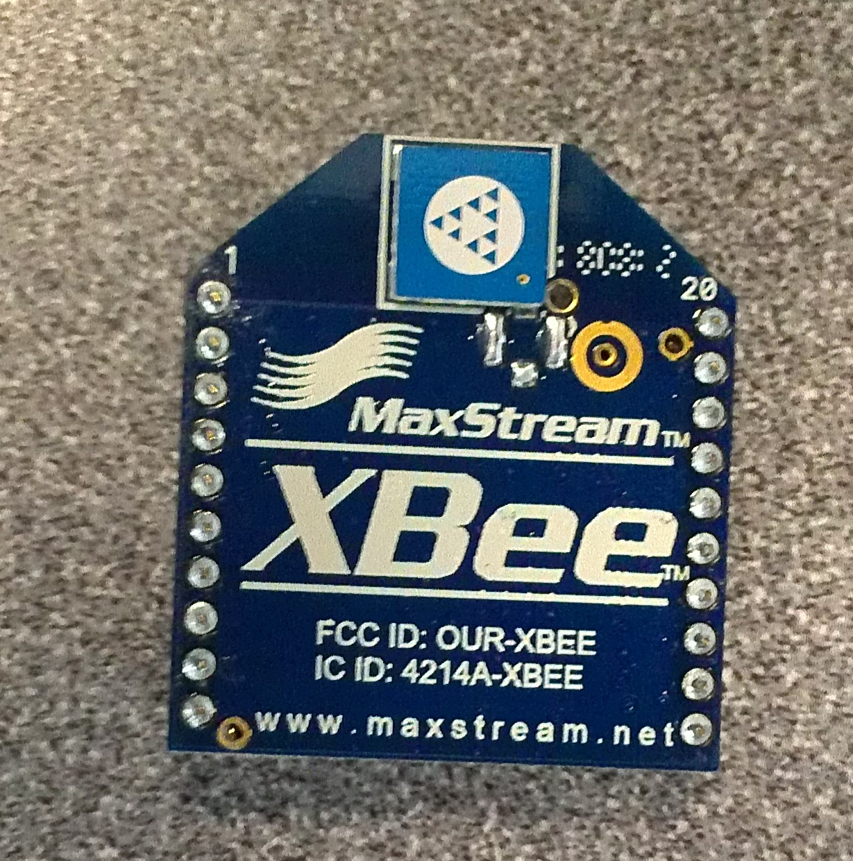
The figure below shows what a typical XBee looks like.
Before getting XBees to communicate with each other, it may be necessary to configure. This tells the XBees which channel they will send or receive data from and which XBee they are communicating with. Configuring can be done easily with the use of a software called X-CTU . The X-CTU program can be found under Diagnostics, Utilities and MIBs .
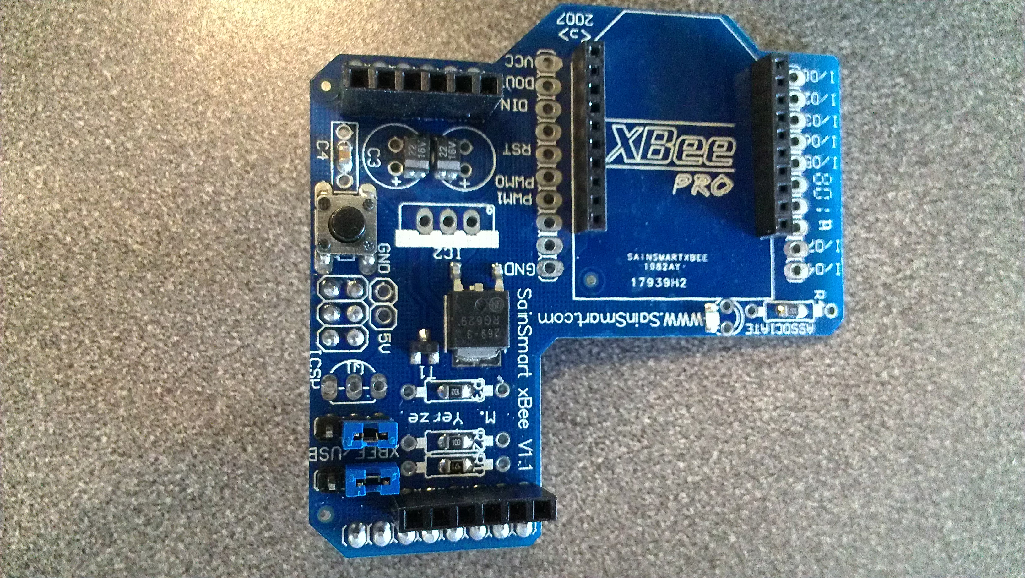
There are two diff erent boards that can be used for confi guration. The XBee Explorer USB board is available through Sparkfun . The SainSmart XBee Shield module , as seen below, can also be used to con figure XBees with the use of an Arduino.
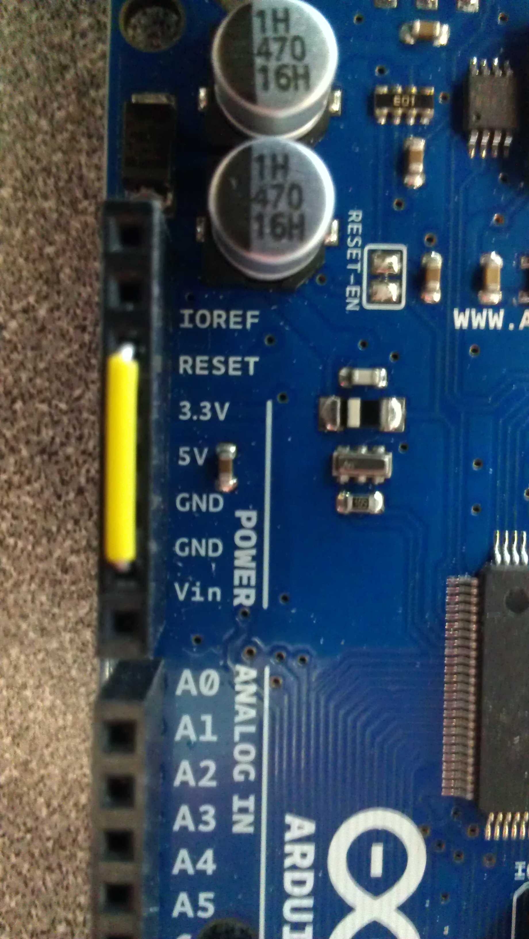
Note: If the XBee Shield module is being used, put your Arduino in reset, which means run a wire from reset to ground as seen below, and make sure the jumpers on the shield are set to USB. Put the shield on the Arduino.
Plug either the Arduino and shield or the Explorer board into the computer and then start the X-CTU program. The program should be able to open up and display a screen similar to the one below.
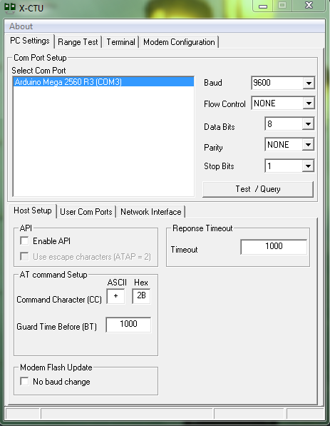
Notice how it recognized the product being used. It should be noted that this is the PC Settings tab. In this tab, there should be a Test/Query button on the right. An example of the screen print out can be seen below.

From this screen, the Serial Number High (SH) and Serial Number Low (SL) can be found for the Arduino. This can be done by breaking apart the Serial Number. Each SH and SL can be eight hexadecimal digits long; however, the SL will be eight long and the SH can be shorter. For example, the above figure shows a SH of 13A200 and a SL of 404AC735.
Go to the Modem Con guration tab and select the Download new versions button. Wait for the download to fi nish and then select the Read button. This will read some of the data in the XBee, as seen below. If the XBee has not been con figured before, it will not read the SH or SL from it, so that information must be obtained from the Test/Query screen. Repeat these steps with the other XBee and make sure to know which SL and SH belong to each XBee.

Now configuration can begin:
- Select one of the XBees, which will now be referred to as XBee 1, and plug it back into the board; the other XBee will now be referred to as XBee 2.
- Read XBee 1 to make sure it has the expected SL and SH values. This should also set the Modem to the Modem of the XBee.
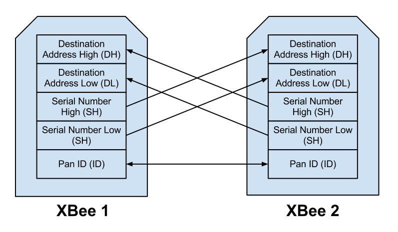
- Change the Destination Address High (DH) of XBee 1 to the SH of XBee 2.
- Change the Destination Address Low (DL) of XBee 1 to the SL of XBee 2.
- This is not necessary to change, but in order to avoid interference with other XBees, it would be prudent to change the Pan ID (ID) of the XBee as well to a number below FFFF, such as 2222.
- Select Write after all the changes have been made.
- Unplug XBee 1 and plug in XBee 2.
- Read XBee 2 to make sure it has the expected SL and SH values. This should also set the Modem to the Modem of the XBee.
- Change the DH of XBee 2 to the SH of XBee 1.
- Change the DL of XBee 2 to the SL of XBee 1.
- If you changed the ID of the XBee 1, make sure you change the ID of XBee 2 to the same value.
- Select Write after all the changes have been made.
The following figure gives a graphical representation of this.
The two XBees should now be configured to communicate with each other. This means that coding to connect the two may now be done and the wireless communication is ready to go.