Arduino
ArduinoPreface
Arduino is an awesome way to get into robotics. It is a very easy to use microcontroller that you program in C/C++. It does analog digital on/off input and output, reading of voltages, anolog output by Pulse Width Modulation (PWM) which is useful for hooking up motors, serial communication which is useful for communicating with sensors and other external devices.
A simple Arduino program example is blinking an LED. The code looks like this:
int led = 13; // Pin 13 has an LED connected on most Arduino boards.

void setup() {               // the setup routine runs once when you press reset:
  pinMode(led, OUTPUT);      // initialize the digital pin as an output.
}

void loop() {                // the loop routine runs over and over again forever:
  digitalWrite(led, HIGH);   // turn the LED on (HIGH is the voltage level)
  delay(1000);               // wait for a second
  digitalWrite(led, LOW);    // turn the LED off by making the voltage LOW
  delay(1000);               // wait for a second
}
Not too hard, right? We have lots of tutorials on how to do more advanced things with your Arduino.
Pulse Width Modulation with analogWrite
Pulse Width Modulation with analogWritePulse Width Modulation (PWM) is used because a microcontroller cannot easily send a specific voltages. It really can only turn a switch on and off. To be able to send a ratio of the current voltage, something like a variable resistor would need to be digitally controlled, but we don't have that. Instead, what PWM does is essentially flip the switch really really fast. That way the average voltage can be varied by leaving the switch on for longer or shorter than it is off.

So, the average voltage is the percent duty cycle, multiplied by the "on" voltage.
Arduino Example
To get 2.5 average volts, just use a 50% duty cycle, since the Arduino outputs 5V normally.
However, the PWM function in arduino does not take duty cycle as a percentage. It takes it as a whole number out of 255. So, a 100% duty cycle would be 255. The 50% duty cycle would be 0.50 * 255 = 127.
Be sure to use a pin on the Arduino that has a ~ next to it, which represents that the pin can do PWM. Not all pins can. On an Arduino Uno, the available pins are 3, 5, 6, 9, 10, and 11. In this example, we will use 5 for no particular reason.
The resulting code to output 2.5 average volts will look like this:
analogWrite( 5, 127 ); // pin 5, half of 255 for 50%
Reading Numbers From Serial
Reading Numbers From SerialIntroduction
Reading numbers from serial on an Arduino is needed surprisingly commonly. Exactly what is happening might be kind of hard to figure out.
Serial
Serial communication is digital, which means all data is transmitted in 1's and 0's. Typically, serial communication is done using ASCII letters. This means that, to send a number to the Arduino, the data sent is not the binary version of the number in base 2 (as an integer), but instead a sequence of characters for each digit in base 10 (which is human-readable). It is not an efficient use of bandwidth, but bandwidth is not usually a problem with Arduinos connect by USB.
Arduino Code
char commandLetter;  // the delineator / command chooser
char numStr[4];      // the number characters and null
long speed;          // the number stored as a long integer

void serialEvent() {
  // Parse the string input once enough characters are available
  if(Serial.available() >= 4) {
    commandLetter = Serial.read();

    //dump the buffer if the first character was not a letter
    if ( ! isalpha( commandLetter ) {
      // dump until a letter is found or nothing remains
      while(( ! isalpha( Serial.peak() ) && Serial.available()) {
        Serial.read(); // throw out the letter
      }

      //not enough letters left, quit
      if ( Serial.available() < 3 ) {
        return;
      }
    }

    // read the characters from the buffer into a character array
    for( int i = 0; i < 3; ++i ) {
      numStr[i] = Serial.read();
    }

    //terminate the string with a null prevents atol reading too far
    numStr[i] = '\0';

    //read character array until non-number, convert to long int
    speed = atol(numStr);
    Serial.println(speed);
  }
}
Code Explanation
serialEvent
serialEvent is a function that is called by Arduino before each loop. So, you can separate out your serial handling from the rest of your code. You could also put the contents of this function in the loop() function and it would be similar.
Fixed-Width
Commands need to be delineated in some way. Fixed-width commands are convenient on Arduino because the Serial.available function tells you how many characters are waiting. It is also possible to delineate by special characters. An extremely common and simple version of this is a Comma Separated Value file. However, since it is simplest to use C strings, the character arrays which the serial is read into is necessarily fixed-width anyway. To get around this issue, a vector or linked list could be used, so the serial string can dynamically grow and shrink.
Command Differentiation
In many cases, a robot takes multiple kinds of inputs. For example, there might be multiple speeds, or a direction, or some kind of trigger. Prefixing each command with a unique letter can make it easy to differentiate what the following string is supposed to do.
C Strings
C strings are arrays of char data types. They must be terminated by a NULL character '\textbackslash 0'. Without the NULL character at the end, there is no way for any function to know how long the string is. For example, a print function would print the string and then a bunch of garbage characters until it gets to a NULL or the end of the memory available. In this case, it's less likely for that to happen since we are only using atol, which will only read until there is a non-numeric character. A non-numeric byte is more likely to randomly be at the end of the string than a NULL character.
| Decimal | Character |
| 48 | '0' |
| 49 | '1' |
| 50 | '2' |
| 51 | '3' |
| 52 | '4' |
| 53 | '5' |
| 54 | '6' |
| 55 | '7' |
| 56 | '8' |
| 57 | '9' |
Char to Integer
Converting a single character to a number takes advantage of how characters are stored, which is typically in a format called ASCII. Think of a char of ASCII like an integer data type. Except that when printed, it is not a decimal number. The number in the int is translated into a letter on the screen according to a table. For example, the decimal number 97 is translated into the letter 'a'. Each letter is really stored as a 'number'. I'm showing it as a decimal (base 10) number, but it is really stored in binary (base 2). The C++ compile takes care of translating our base 10 decimal numbers into base 2 binary.
Here is how to take advantage of this:
int number = (int)charInput - (int)48;
// or:
int number = charInput - '0';
Since ASCII stores the letters sequentially, starting at 0, just subtract the value where 0 begins from each of the characters to convert it to its numeric form. This works regardless of the base of the character storage. So, it converts the ASCII character representing the number in base 10 into an integer in base 2.
Char Array (C-string) to Long Integer
Now, each of the letters from right to left need to be multiplied by a power of 10. Here is the basic idea of what atol does:
char charArray[5] = "5432"; // double quotes adds the \0 at the end

long longnum = 0;  //the converted number
long exp = 1;      //start with 10^0
int index = 0;     //the current place in the array

//find the end of the string - when character is not a number
while ( isdigit( charArray[idx] ) ) {
    ++idx;
}

//begin base multiplication and number conversion
while( idx >= 0 ) {
    //convert digit character to a long
    long currentDigit = (long) charArray[idx] - (long)48

    currentDigit *= exponent; //number multiplied by 10^(len-idx)
    exponent *= 10; // next number to left is another power of ten

    longnum += currentDigit;

    --idx;
}
Serial Commands
Serial CommandsIntroduction
Serial communication through USB can be used to communicate between a host computer (like a laptop, or Raspberry Pi), and an Arduino. Doing so allows:
- Use of the faster hardware of the host computer for calculations
- Synchronization of multiple Arduinos
- Use of other information provided by the host computer, like internet connections or larger data files
- Creation of a graphical interface using the host's display or web server
Communication
Communication is easy. Arduino and Python have simple methods for establishing serial communication.
Arduino
void setup() {
    Serial.begin(9600); //Initialize serial communication at 9600 baud
}
void loop() {
    Serial.println('hello');
}
Python
from serial import *
ser = Serial( "/dev/ttyACM0" , 9600 )

while 1:
    print ser.readline()
Incomplete Messages
One of the most difficult issues with this sort of serial communication is ensuring that commands are received in entirety. If you send "1000" from Python, and want Arduino to read it as shown below, Arduino might read "10" and then in another loop() right afterward read "00".
char incoming[11] = "          ";
int i = 0;
while (Serial.available() > 0) {
    // read the incoming byte:
    char[i] = Serial.read();
    i++;
}
//Convert the incoming string into an integer!
int newNumber = atoi(incoming);
Fixed Length Packets
One way to solve this in an efficient manner is to use a fixed length for commands and wait until there are enough bytes waiting in the buffer. The downside is that no commands may be issued with a length longer than the fixed length, and requires remaining length be wasted.
Python
ser.write('%10d' % 1000 ) #pad the number so it is 10 characters long
Now just add a condition so that no reading is done unless a full command is waiting in the serial buffer.
Arduino
if ( Serial.available() >= 10 ) {
    char incoming[11] = "          ";
    int i = 0;
    while (Serial.available() > 0) {
        // read the incoming byte:
        char[i] = Serial.read();
        i++;
    }
    //Convert the incoming string into an integer!
    newNumber = atoi(incoming);
}
Delineation
Another way to solve this problem is to delineate commands by placing a special character at the end of each command to signify that the command is complete. The problem with this way is that the length of the incoming string is unknown, and a long or improperly formed command could overflow a fixed length array. To overcome this limitation, a dynamic class is usually used. The String object is a good solution as it can be easily converted back into a character array. Maintaining data types with C++ strings can quickly become confusing, and it is extremely important that the delineation character is never used in the command. There are some special command characters in ASCII that would be good choices.
Multiple Command Types
You can send different commands over the same communication line by attaching a prefix to the command. For example, speed and position could be sent as "p000001000" and "s000000200" to tell the Arduino to go to position 1000 at a speed of 200.
Python
ser.write('p%9d' % 1000 ) #send position, padded to 9 (plus 1 command char)
ser.write('s%9d' % 200 )  #send speed, padded to 9 (plus 1 command char)
Arduino
int position, speed;
if ( Serial.available() >= 10 ) {
    //read the first character as the command
    char command = Serial.read();

    char incoming[10] = "         ";
    int i = 0;
    // read the incoming byte:
        char[i] = Serial.read();
        i++;
    }
    //Convert the incoming string into an integer, based on command
    if ( command == 'p' ) {
        position = atoi(incoming);
    }
    else if ( command == 's' ) {
        speed = atoi(incoming);
    }
    else {
        //The command was not one of the recognized characters
        Serial.println("COMMAND ERROR - Not recognized");
    }
}
Now that your communication is established, it is up to you to figure out what to do with the data on either end.
Splitting a String
Splitting a StringIntroduction
There are times when a string is recieved, but rather than the entire string, just a piece of the string is desired. Unfortunately, there does not appear to be a simple way to handle strings in C++. Therefore, I have devised a way to split a string based on comma separation.
This way of splitting strings is rather crude and refinement for it will be worked on, but for immediate use, the current function is given with two examples of how it can be altered and used.
Coding
Splitting Strings - Two Characters
This code was used in a project that controlled a robot via computer. The computer sent data through an XBee to an Arduino that served as the brains. That Arduino would get the string from the computer, pick it apart and find the important information. That information was then relayed to an Arduino that controlled the robot's motors. The single character that was sent to the motor Arduino then told which direction to move the robot in.
//Brain Code

char string[25];
char id[2];
char direct[2];


int ii=0;

void setup() {
  Serial.begin(9600);           // set up Serial library at 9600 bps
  Serial1.begin(9600);
  //Serial.println("Motor test!");
}

void loop() {
}

void serialEvent() {
  int i=0;
  if (Serial.available()) {
    delay(50);
    while(Serial.available()) {
      string[i++] = Serial.read();
    }
    string[i++]='\0';
    splitString(string);
    if (id[0] == 'M') {
      Serial1.print(direct[0]);
    }
  }
}

void splitString(char* chars) {
  char val1[15]={};
  char val2[15]={};

  int i=0;
  int cnt_id,cnt_val1,cnt_val2;

  //get identifier
  while(chars[i] != ',' && i<25) {
    i++;
    if (chars[i] == ',' || chars[i]=='\0') {
      for(int j=0;j<i;j++) {
        id[j] = chars[j];
        cnt_id=j;
      }
      id[cnt_id+1]='\0';
      //Serial.println(id);
    }
  }

  i++; //skips the comma

  while(chars[i] != '\0' && i<25) {
    i++;
    if (chars[i] == ',' || chars[i]=='\0') {
      for(int j=cnt_id+2;j<i;j++) {
        direct[j-(cnt_id+2)] = chars[j];
        cnt_val1=j-2;
      }
      direct[cnt_val1+1]='\0';
      //Serial.println(direct);
    }
  }
}
A question may arise of why even bother with this code? Why not directly send to the motors which direction to move? And in this case, yes, that would have been much simpler. However, this is one part of a much bigger project where more than just motor information will be sent, so the first character being sent in will indicate which part of the robot it pertains to.
Splitting Strings - Getting Floats
Often times, it may be necessary to send actual number values, whether that is a float or an integer, through serial. Therefore, there needs to be a way to recover that data. It can be sent as a byte, but floats and larger integers may not fit into a byte.
For example, in a project it was necessary to send a string like "L,1234.5678,2345.6789" through serial to an Arduino. This is intepretted as sending a Location to the Arduino with the following coordinates. This would involve both splitting up the string and turning the number values into floats.
Unfortunately, there are not very elegant ways to handle strings in C, so two functions had to be made by scratch to split the string. In this particular example, this was the only type of string that was going to be sent to the Arduino, so code was made to split this specific string, but it can be adapted to other means.
The following code shows how the string is split:
void splitString(char* chars, char* id, double &numX, double &numY) {
  char val1[15]={};
  char val2[15]={};

  int i=0;
  int cnt_id,cnt_val1,cnt_val2;

  //get identifier
  while(chars[i] != ',' && i<25) {
    i++;
    if (chars[i] == ',' || chars[i]=='\0') {
      for(int j=0;j<i;j++) {
        id[j] = chars[j];
        cnt_id=j;
      }
      id[cnt_id+1]='\0';
    }
  }

  i++; //skips the comma

  //get first float
  while(chars[i] != ',' && i<25) {
    i++;
    if (chars[i] == ',' || chars[i]=='\0') {
      for(int j=cnt_id+2;j<i;j++) {
        val1[j-(cnt_id+2)] = chars[j];
        cnt_val1=j-2;
      }
      val1[cnt_val1+1]='\0';
      CharToFloat(val1, numX, cnt_val1+1);
    }
  }

  i++; //skips the comma

  //get second float
  while(chars[i] != '\0' && i<25) {
    i++;
    if (chars[i] == ',' || chars[i]=='\0') {
      Serial.println(chars[i]);
      for(int j=cnt_id+cnt_val1+4;j<i;j++) {
        val2[j-(cnt_id+cnt_val1+4)] = chars[j];
        cnt_val2=j;
      }
      val2[cnt_val2+1]='\0';
      CharToFloat(val2, numY, cnt_val2+1);
    }
  }
}
It may be noticed that in this case, a function CharToFloat is called. This function is explained in another tutorial. It is one method for turning character arrays into more precise floats.
Character Array to Float
Character Array to FloatIntroduction
Sometimes it is necessary to turn character arrays into floats. However, precision can be an issue when using some of the current functions. The following function turns character arrays into a float that is split from the front half and the back half. This is one method for a more precise float.
Coding
The following code shows the CharToFloat function that turns the split Character Array into a float. It should be noted that the function splits the float into a forward half and a back half. This is due to the Arduino's capabilities. Floats can only ever have 7 digits, which means if you need anymore than that, the accuracy of the float decreases. It will remember 7 of the numbers and then make the best guess it can for the rest. This can be a problem if precision is key.
And, no, using double will not fix the problem. In the Arduino, float and double are the same thing. Therefore, splitting the float into two sections can retain the accuracy with some inconvenience.
void CharToFloat(char* chars, double* value, int count) {
  int i=0, l=0;
  float multiplier;
  float front =0.0, behind =0.0;
  value = 0.0;

  //before demical point
  while(chars[i]!='.' && i<count) {
    i++;
    if (chars[i]=='.') {
      int q=i;

      for(int j=i; j>0; j--) {
        multiplier=1;

        for(int k=q; k>1; k--) {
          multiplier *= 10;
        }

        front+=(chars[l]-'0')*multiplier;
        l++;
        q--;
      }

      l++;
    }
  }

  int n=i;

  //after demical point
  while(chars[n]!='\0' && i<count) {
    n++;
    if (chars[n]=='\0') {
      int q=n, l=n-1;

      for(int j=n-1; j>i; j--) {
        multiplier=1;

        for(int k=q-(i+2); k>=0; k--) {
          multiplier = 0.1*multiplier;
        }

        behind+=(chars[l]-'0')*multiplier;
        l--;
        q--;
      }
    }
  }

  value[0]=front;
  value[1]=behind;
}
This may not be the most elegant way to turn a character array into a float, but it works. Needless to say, this does not appear to be common practice, but seems like it might be a common problem.
Arduino to Arduino Serial Communication
Arduino to Arduino Serial CommunicationIntroduction
It is possible to chain Arduinos together in such a way as to get communication between the two. Having Arduino-Arduino communication can be useful for many projects, such as having one Arduino to run motors and having another sense the surroundings and then relay commands to the other Arduino. This can be done in several methods, using I2C and Serial, to list a few.
This tutorial will focus on Arduino-Arduino communication through the serial ports (RX and TX).
Schematic
The schematic below shows how to connect the two Arduinos together. This shows two Unos, but if a Mega is used, it can be connected to any of the Serial ports on the Mega as long as that is accounted for in the code.
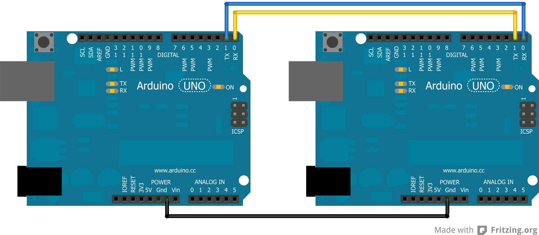
There has to be a common ground between the two or else it will not function properly. Also, note that TX goes to RX and RX goes to TX.
Coding
When sending things through serial, everything is sent in bytes. These bytes are then read one byte at a time by the other Arduino. When it is just characters being sent through the serial, it is relatively easy to convert from characters to bytes. However, if there are both characters and numbers are going through, this can lead to messing up the data because a number and a character can have the same byte value, but that does not make them the same. Numbers are also tricky because they may not actually fit in the byte.
Simple Code
The easiest way to get around this is to try to avoid using characters and numbers at the same time. This can be done by sending one character across, each with a different meaning. A good example of this comes from the Arduino Physical Pixel tutorial.
Upload the Physical Pixel code, which can be found in the Arduino IDE under: File >> Examples >> Communication, onto one Arduino.
On the other Arduino, upload:
void setup() {
  Serial.begin(9600);
}

void loop() {
  Serial.print('H');
  delay(1000);
  Serial.print('L');
  delay(1000);
}
When this is run, the LED attached to Pin 13 on the Arduino with the Physical Pixel code should flash on and off at a frequency of 0.5 Hz. To make sure this is actually the code doing that, the delays can always be changed in the above code.
In this code the job of 'H' was to turn an LED on and the job of 'L' was to turn the LED off. This can easily be applicable to getting various characters triggering more reactions.
However, depending on the application, this may not be enough and more drastic code may be required.
Complex Code
For sending data from one Arduino to another in a form that cannot be simplified, there are other options. One option is to turn everything sent from the Sender Arduino into characters and then have the Receiver Arduino read in the characters. The data is actually sent as bytes, but the Arduino can convert from characters to bytes and vice versa.
Sender Code
The sender code changes characters into bytes and, if necessary, it changes number values into characters before turning it into bytes. Below is a sample of the Sender code:
//Sender Code

char str[4];

void setup() {
  Serial.begin(9600);
}

void loop() {
  int value=1234; //this would be much more exciting if it was a sensor value

  itoa(value, str, 10); //Turn value into a character array
  Serial.write(str, 4);
}
Receiver Code
The receiver will then receive the byte array from the other Arduino and interpret it there. Below is the code for the receiver. Note that this code is intended for a Mega since it will interpret the data received from the other Arduino and then print to the Serial Monitor what it received so that the user can check it. This debugging can be avoided by using an Uno and then printing what was found onto an LCD screen that uses I2C communication.
//Receiver Code

char str[4];

void setup() {
  Serial.begin(9600);
  Serial1.begin(9600);
}

void loop() {
  int i=0;

  if (Serial1.available()) {
    delay(100); //allows all serial sent to be received together
    while(Serial1.available() && i<4) {
      str[i++] = Serial1.read();
    }
    str[i++]='\0';
  }

  if(i>0) {
    Serial.println(str,4);
  }
}
There is one flaw with this program as it is now. It results in only a character array, so if the integers were desired, they are lost without further work on the data.
Further tutorials have been made to show how this data may be manipulated by splitting strings or getting floats from the character arrays.
Optimized Multiple Pin Reads
Optimized Multiple Pin ReadsMemory Addressing
First, to understand why things are done this way, it should be known that a bool (boolean true/false) is only 1 bit. 1 for true, 0 for false. However, computers have an addressing system for memory, which cannot go directly to a single bit. An address usually goes to a 8 bit chunk of memory (a byte), which is also usually the same size as an int data type.
Think of it like trying to write a postal address to a room in a house. The address will take you to the house, but not inside. So, we can't just keep it in its own variable.
Furthermore, it would be wasteful to waste 7 bits for every bool declared. 8 bools can be put all into one integer - all next to each other in memory - to save space. How do you seperate them? How do you get just one bit out of a chunk of bits? With boolean logic!
Port Manipulation
To be as efficient, Arduino groups pins together into 8 bit "int" variables. Using boolean logic, you can perform operations on pins yourself, instead of using the built-in functions. This is called Port Manipulation. There are 3 groups of 3 variables. First, the pins are broken up into groups of 8 based on number.
- D: Arduino digital pins 0 to 7
- B: Arduino digital pins 8 to 13
- C: Arduino analog pins 0 to 5
Then, there are 3 types of registers which can perform different actions, each with a the corresponding letter replacing the '#':
- DDR#: Data Direction Register.
- Sets whether the each pin is read from or written to.
- PORT#: Port I/O
- Can write to each pin a high or low state, but can also be read
- PIN#: Pin Input
- Can read the current pin states of the pins in input mode.
Reading the pins
Pins are oranized in the register from lowest number at the right, to highest number at the left In this example, pins 11 through 13 are set as INPUT. Pins 11 and 13 are currently high at the moment, but pin 12 is low.
| Pin: | NA | NA | Pin 13 | Pin 12 | Pin 11 | Pin 10 | Pin 9 | Pin 8 |
|---|---|---|---|---|---|---|---|---|
| Decimal Value | 128 | 64 | 32 | 16 | 8 | 4 | 2 | 1 |
| PINB | 0 | 0 | 1 | 0 | 1 | 0 | 0 | 0 |
| SelectP13 | 0 | 0 | 1 | 0 | 0 | 0 | 0 | 0 |
| SelectP11 | 0 | 0 | 0 | 0 | 1 | 0 | 0 | 0 |
As you can see, if you were to print the value of PINC with pins 13 and 11 high but 12 low, the value with 32 + 8 = 40.
To select a single pin out of the PINC register, bitwise AND it with an int in the same place as the pin. So, PINB & SelectP13 = 13, or 0B00100000. Conditions in C++ will be true for any nonzero value. If Pin 13 were low, then the result would have been 0, or 0B00000000.
Programming Example
First, you have to set whether the pins are in read or write mode. Since this is often done exclusively in setup and only once per program, it is not as important to optimize this. It may be easiest to just use pinMode() to set the states instead of the more advanced ways described below with the DDR# register.
void setup() {
    pinMode(11, INPUT);
    pinMode(12, INPUT);
    pinMode(13, INPUT);
}
void loop() {
    //This condition is a single CPU operation
    //pins 11,12, and 13 are all in the PINB group at the left
    if ( PINB & 0B11100000 ) {
        Serial.println("Pin 11, 12, or 13 were high");
    }

    //this condition requires dozens of operations
    if ( digitalRead(11) || digitalRead(12) || digitalRead(13) ) {
        Serial.println("Pin 11, 12, or 13 were high");
    }

}
In the above example, the slower second method each digitalRead must first figure out which register the pin is in, select it with a bitwise and, and return it to the condition. Then, each pin state must be ORd together.
Obviously, this case is not a typical one, but there are other uses. For example, one could write to several pins at once. This optimal method becomes extremely important when speed is an issue. When reading pins every few microseconds on interrupts, it can be beneficial to first store the whole register into a buffer, then do the required comparisons later in order to insure that all changes are being captured. Otherwise, data could be lost if the interrupt function is interrupted before it can complete.
Build Arduino Sketches from CLI with Make
Build Arduino Sketches from CLI with MakeReasons
The Arduino IDE has a lot of nice features. It's so easy, it's really one of the main reasons why you would choose to buy an Arduino over other options. It can be annoying sometimes though. If you want to distance yourself from the IDE, but still like the Arduino plaform, it's really as easy as just making a really simple text file and running "make".
By getting a command line interface, you can also automate the build and upload process. You can detect ports, or upload to multiple Arduinos at once.
Installation
Ubuntu command:
sudo apt-get install avrdude make gcc-avr arduino-mk
Usage
Create a text file called "Makefile" in the same folder as your project
ARDUINO_DIR  = /usr/share/arduino

TARGET = projectName         # The same as your ino file name

BOARD_TAG    = uno           # can also be mega2560
ARDUINO_PORT = /dev/ttyACM0  # be sure to change this to the port used by your board

#Can add Arduino libraries. Example:
#ARDUINO_LIBS = EEPROM

ARDUINO_DIR  = /usr/share/arduino
AVR_TOOLS_PATH = /usr/bin

include /usr/share/arduino/Arduino.mk
Once you have that file, all you need to do is just say:
make upload
If you aren't using an Arduino Uno, you can check which boards are available with:
make show_boards
Advanced Usage
It might be helpful to just autodetect all of the Arduinos connected and upload the same image to all of them. Here is a nice simple way to do that with bash:
Makefile:
ARDUINO_DIR  = /usr/share/arduino

TARGET = tempTargetName
BOARD_TAG    = uno
ARDUINO_PORT = ${arduino}

ARDUINO_DIR  = /usr/share/arduino
AVR_TOOLS_PATH = /usr/bin

include /usr/share/arduino/Arduino.mk
Then make a bash file. This will be executed instead of the make command.
make.sh:
#!/bin/bash

#look for any Arduinos.
#The current ones were connected recently and within the same minute

for a in `ls -lt /dev/ttyACM* | awk 'BEGIN{first = 1} {if (first) {current = $9; first = 0} if ( $9 == current ) { print $10} else{exit} }' `
do
    echo "uploading to $a"
    make arduino=$a upload
    if [ $? -ne 0 ]; then
        echo "nonzero return status"
        exit
    fi
done
Now, all you need to do to compile and upload to all recently connected arduinos is run:
bash make.sh
Kernel - Event driven Delays and Intervals
Kernel - Event driven Delays and IntervalsReasons to use Kernel
delay() is Bad
When you use delay or delayMicroseconds in Arduino, nothing else can happen until the delay is finished, which can be a huge problem if you have more than one thing going on simulteneously, as will always be the case when building a more advanced robot.
Imagine that you want to check a sensor once a second. Easy enough. Just delay then check the sensor. What if you want to blink an LED on and off every 40ms, but still checking that sensor. Any delays used by one will mess up the timing on the other. If you delay one second after checking the sensor, the light will not blink during that time. You could make a fixed number of blinks between sensor checks, but that is inflexible and accumulates error.
Problems with Alternatives
Two alternatives already exist. Both are based on the idea of constantly asking "can I go yet?" in an if statement.
- You can check the times yourself, but that requires a lot of work and can make the code hard to read.
- You can also use Metro , which wraps the check up into a nice class where you just set an interval and run a .check() method.
I really like Metro, but it still requires the program to be written somewhat linearly instead of in seperate functions, and it is not really meant to be used for one-time delays.
If you are using an Arduino Due, there the Scheduler library that provides an easier interface, but is exclusive to the Due's ARM CPU.
Events are Easy and Powerful
If you've ever dealt with GUIs or Javascript, you're probably comfortable with events. They're a nice way to make the most use out of a single threaded application (like a browser window, or an Arduino) because, as long as you avoid any blocking, things happen when they're supposed to.
Essentially, each "task" is a function which gets called only when the "event" happens. The event, for example, can be a timing trigger or a user interaction.
Kernel takes care of timing the event calls. It can automatically maintain both run-once and run-repeatedly events simulteneously.
Since Kernel is keeps track of which event needs to happen next, but still using delayMicroseconds, better timing precision and consistency is achived.
Other Potential Benefits
Since a Kernel is such a advanced framework, with a little additional programming, some really useful features can be added:
It could keep track of how long a task takes to complete, or give more important tasks priorities, and factor that into decisions of which task can go when, like a true kernel would for process management.
A single "background" process could be run, without interfering too much with the time-sensitive tasks. Which could be accomplished with the runNow method.
How it Works
There is a queue of functions. They are in the ordered chronologically. Since it is a linked list, the functions can be inserted in before other functions, but after others.
Now all that Kernel does is look at the next task coming up to see if it is the right time. If it is not time yet, it will use delayMicroseconds to give it a precise start time.
Repeating events (called intervals) will then be re-added to the queue in the correct chronological order.
Since the soonest event is always in the front of the queue, no events will be passed over while using delay.
Basic Usage
First, download the kit - ![]() kernelTest.zip. It includes Kernel (GPL by me), fastDelegate (Public Domain from Code Project), a modified version of the QueueList library (from the Arduino Playground), and a simple Arduino .ino file to show some basic usage.
kernelTest.zip. It includes Kernel (GPL by me), fastDelegate (Public Domain from Code Project), a modified version of the QueueList library (from the Arduino Playground), and a simple Arduino .ino file to show some basic usage.
The usage is intentionally very similar javascript, which uses setInterval and setTimeout for repeating and one-time tasks respectively.
//may need to use <> instead of ""
// depending on if you installed Kernel as a library.
#include "kernel.h"

Kernel kernel; //this should be a global, so other files can use it too.

void test() {
    Serial.println(  micros()  );
}

void setup() {
    Serial.begin(19200);

    //add a function to interval. It will run every 10,000 microseconds.
    kernel.setInterval(10000UL, test); // UL means the unsigned long
}

void loop(){
    //should avoid any code that could cause much delay here

    // runNext decides whether to delay or run the next function
    kernel.runNext();
}
That's it! In a lot of ways, it's even cleaner than a Metro. Of course, there is a lot more going on under the hood.
This above example shows how to add an interval. It is also possible to add a timeout by using setTimeout instead, which will only happen once.
Sidenote about Unsigned Longs (UL)
Intervals and timeouts are set in microseconds. Since microseconds add up so quickly, Arduino deals with them as unsigned longs, but they still overflow (go back to zero) after about 70 minutes. The setInterval and setTimeout functions take durations in microseconds stored in unsigned longs too. Sometimes, it might be necessary to say that the what the type of the constant you have in your code is. For example, if you are dividing numbers, you might prefer to use a 2.0 instead of a 2, since a 2 is an integer and might typecast the other number into an integer also - removing the decimal precision. Similarly, problems might or might not happen with very long numbers represented by long and unsigned long. Arguments will by typecast into an unsigned long, so it will probably not be necessary to specify "UL" at the end of your numbers.
Advanced Usage
Remove a task
Both setInterval and setTimeout return a unique integer PID. It can be used to later remove a task from the queue.
int newPID = kernel.setInterval( 100000UL, test);
kernel.clearInterval( newPID );
Remove all tasks
Perhaps all current tasks need to stop happening. Maybe you've come accross an error and want to stop everything.
kernel.stopALL();
Break Up a Long Task
Sure, you could create a seperate task for a background task, but if your loop runs quickly enough, you can essentially run kernel like you might a Metro, except it is only checking the next pending task.
void loop() {
    for( int index = 0; i < hugeArray; i++ ) {
        //do some operations

        // will not delay until next task, tasks may be overdue
        kernel.runNow();
    }
}
You need to do either runNow() frequently, or do runNext() at the end. Otherwise, no events will be called.
Clock Display Without Serial
Clock Display Without SerialIntroduction
This is a tutorial on how to build a clock display using only an Arduino, a Shift Register, and 4 digit seven segment display.
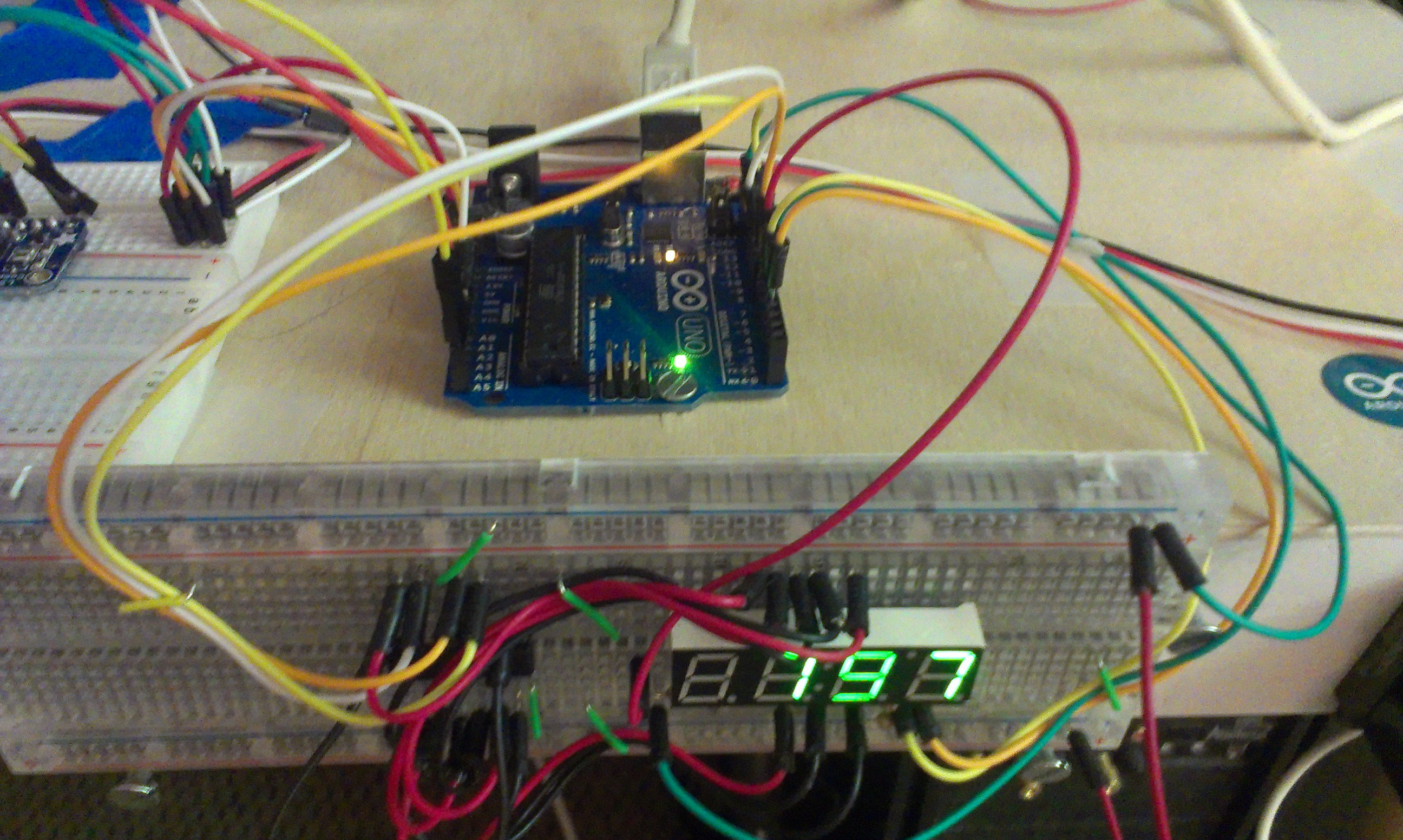
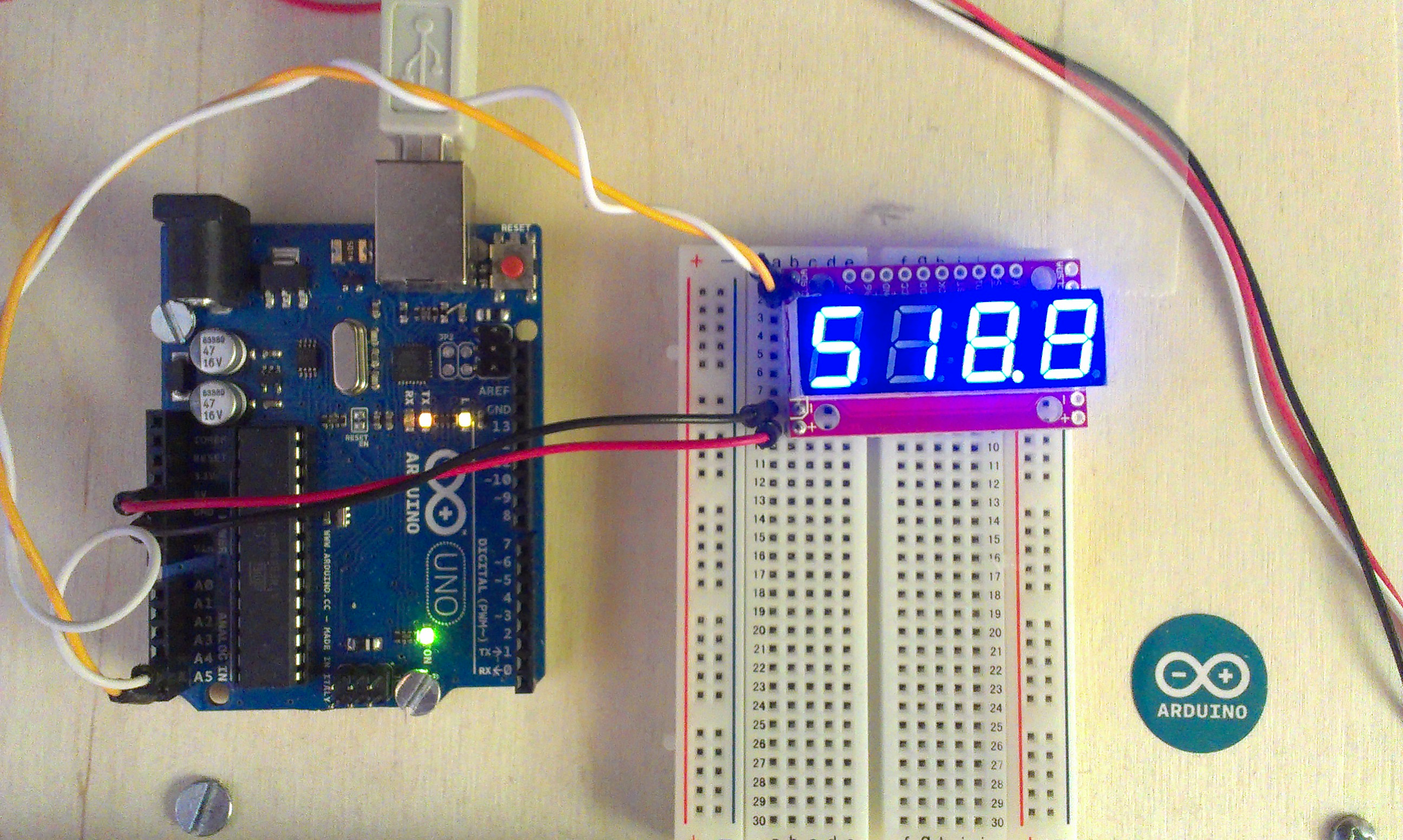
The end result should look something like this mess:
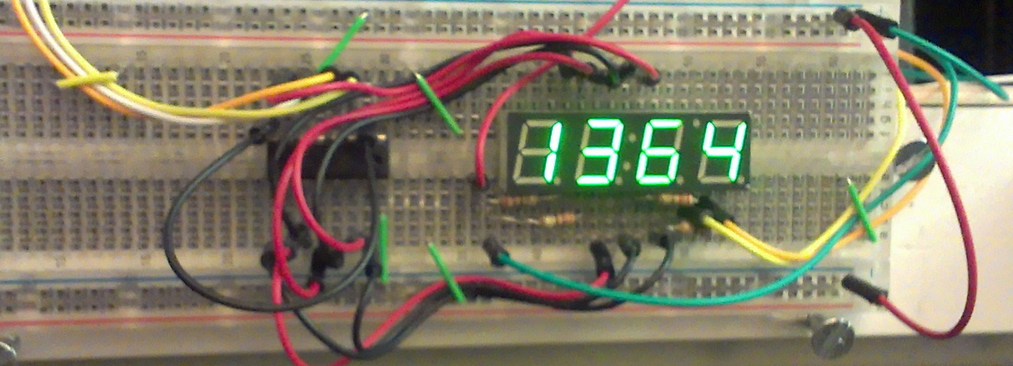
In this image, you can see an accelerometer to the left, which is not a part of this tutorial.
Clearly, the whole thing gets very messy. As a result, I would recommend one that works by serial, offloading this wiring and refreshing. There is a great Arduino-based one by Sparkfun , and a cheaper one available at Adafruit . It's $10-$13 for the serial ones, but these bare displays are 2$, the shift register is 3$ for a pack of three, uses at about 20 breadboard wires, 8 pins on your Arduino, and requires that the Arduino be able to cycle through the digits of the display frequently. The extra cost is minimal and saves a lot of effort.
Parts List
- .39 inch 4 digit 7 segment display (BL-Q39A-42UG-21 from Adafruit )
- 74HC595 Shift Register (bought from Adafruit )
- Arduino Uno
- 4x 220Ω resistors
- Lots of breadoard wire
Pinout of Display
I had some trouble getting the display to work according to the spec sheet, so I just reverse engineered it.
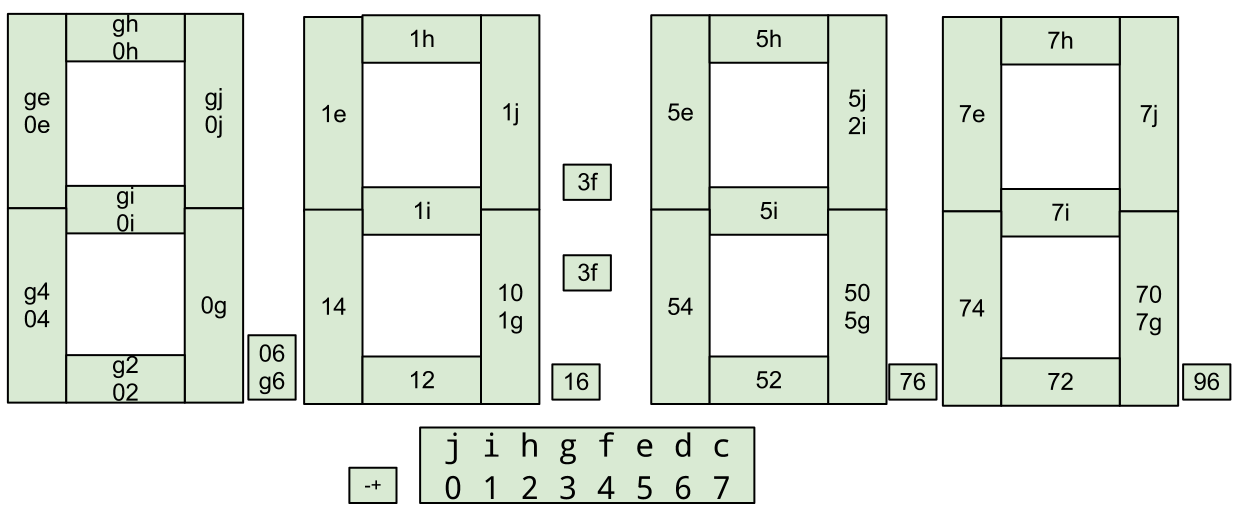
The numbers on the digit segments are in the order of negative and positive. So, to light up the left most digit, 0 must be negative (grounded), and each of the segments can be lit with by giving each of the right most lettered pins a positive. As a result, the grounding pin must be cycled, and the other digits must be positive. Also, apparently the 0 and g pins are interchangable.
Wiring Diagram
I made a wiring diagram in Fritzing. Even like this, it still looks daunting, but at least you can tell what goes where.
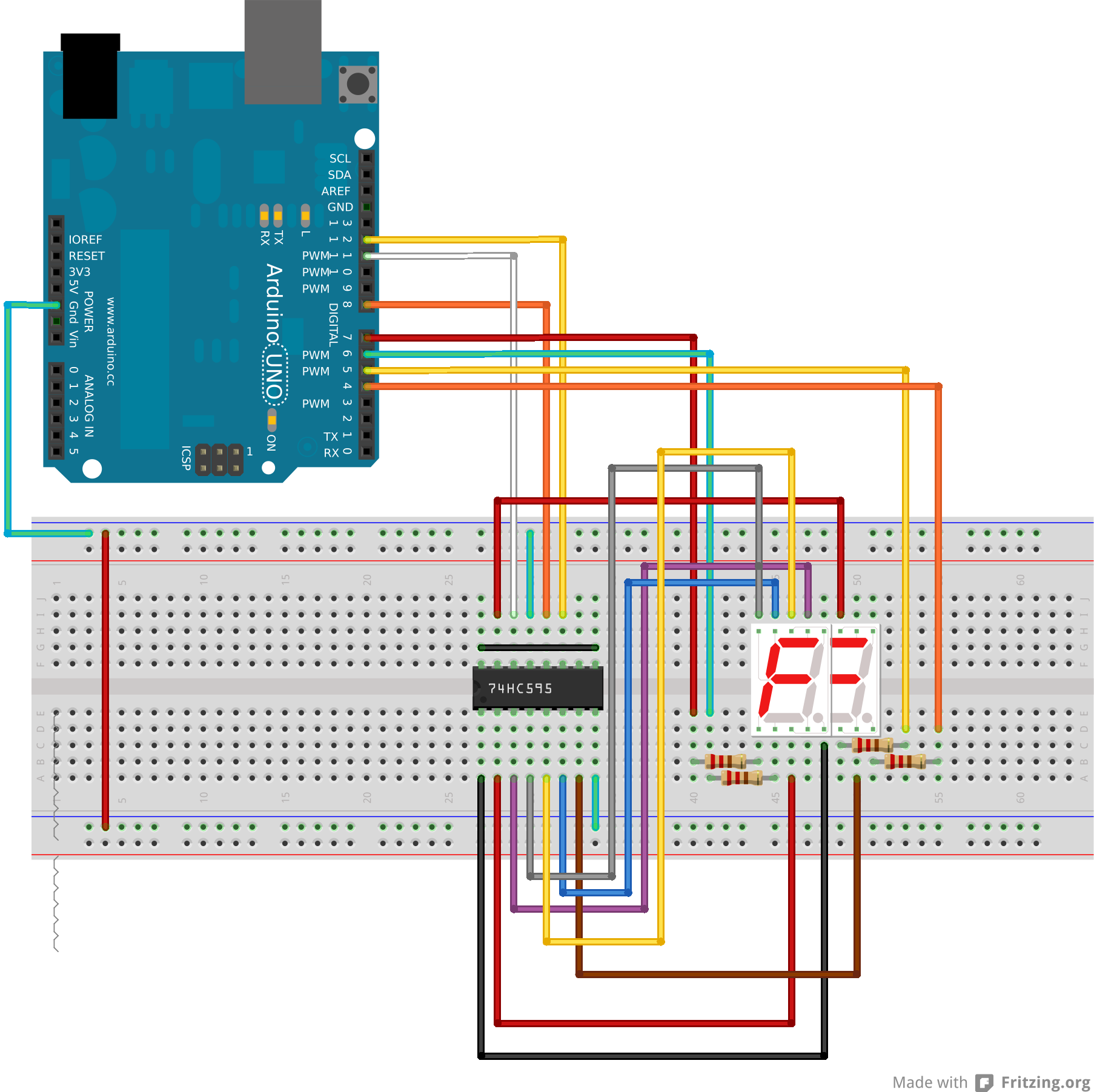
I couldn't find something for a 4 digit seven segment display that has 8 pins on each side. So, I just used two 7 segment displays overlayed so they had the right number of pins. It looks ugly, but pretend it's ok. The wires should still be the same.
The svg and Fritzing files are attached at the bottom as well for your convenience.
Code
The code is also somewhat complicated. There are two main problems: converting a character to a a map of on or off values for each pin, and the fact that the display has to be refreshed ever few milliseconds. I took care of both problems by writting my own class. It should actually be universal for all 7 segment displays with minimal adjustment. I wrote it to utilize the Kernel library I made so that the timing is non-blocking.
The .ino file:
#include "kernel.h"    //handles timing in non-blocking way
#include "SevenSeg.h"  //maps characters to pin outs on shift register

// declare some global instances of the classes
Kernel kernel;
SevenSeg sev;


int count = 0;
void increment() {
    sev.display( count );
    count++;
    if ( count > 9999 ) {
        count = 0;
    }
}


void setup() {
    //set up the seven segment display class
    sev.setup();
    sev.setShift( 8, 12, 11);  //which pins the
    sev.setDigits( 7,6,5,4 );
    sev.setSegmap( 0, 1, 2, 3, 4, 5, 6, 7);

    //takes an Unsigned Long (UL) for the microseconds between intervals
    kernel.setInterval(100000UL, increment);
}

void loop() {
    kernel.runNext();
}
The SevenSeg.h class:
The SevenSeg class should be universal, but you have to do a few things to set it up first.
First, you need to tell it which pins the shift register is on. This is fairly straightforward with:
setShift(latch, clock, data)
The arguments should correspond to the spec sheet for your shift register
- latch: may be denoted as ST_CP, or RCLK
- clock: may be denoted as SH_CP, or SRCLK
- data: may be denoted as DS, or SER
Next, you need to tell SevenSeg which pins are used to toggle which digit is being lit in the cycle. These should be real pins on the Arduino addressable by digitalWrite. The digits are in order from left to right.
setDigits( 7,6,5,4 );
Then, you need to map the digits of the display to the pins on the shift register
setSegmap( ... )
The value of the argument is the pin on the shift register. The order of the arguments says which segment it belongs to according to this:
/*
  0 5555555555555 4
  00 55555555555 44
  00             44
  00             44
  00             44
  00             44
  0 6666666666666 4
  1 6666666666666 3
  11             33
  11             33
  11             33
  11             33
  11 22222222222 33   777
  1 2222222222222 3   777
*/
Conclusion
Download the Arduino code: ![]() sevSegTest.zip
sevSegTest.zip
Again. It's a really really good idea to just get one that works over serial.
Clock Display With Serial - Sparkfun
Clock Display With Serial - SparkfunIntroduction
These seven segment displays are managed by an extra Arduino embedded in them. As a result, far less wiring and code is required for your project, since it is all encapsulated in this nice package. Here is the finished project:
Basic Wiring (I2C)
| Arduino | Serial7Segment |
|---|---|
| A5 | SCL |
| A4 | SDA |
| 5V | + |
| GND | - |
The wiring is really straightforward. On the top sides there is an SDA and SCL, which go to A4 and A5 respectively on your Arduino Uno. If you are using a different Arduino, check the documentation on the Wire library to see which pin you should use.
On the bottom sides, there is a plus and minus, which should be hooked up to the 5V and GND pins respectively on your Arduino.
Basic Code
I based my code on the public domain code posted by sparkfun. I added:
- Number formatting (space padded to the right)
- Use snprintf to handle overflows
- Funciton for decimal printing using floats
- Beware! Floats on Arduino are really innacurate. I get 0.01 error on just a 3 digit number!
/* Serial7Segment is an open source seven segment display.
 To get this code to work, attach a Serial7Segment to an Arduino Uno using:
 A5 to SCL
 A4 to SDA
 VIN to PWR
 GND to GND
*/

#include <Wire.h>

#define APOSTROPHE  5
#define COLON       4
#define DECIMAL4    3
#define DECIMAL3    2
#define DECIMAL2    1
#define DECIMAL1    0

//This is the default address of the OpenSegment with both solder jumpers open
#define DISPLAY_ADDRESS1 0x71

void setup()  {
  Wire.begin();       //Join the bus as master

  Serial.begin(9600); //Start USB serial communication at 9600 for debug prints

  //Send the reset command to the display
  //this forces the cursor to return to the beginning of the display
  Wire.beginTransmission(DISPLAY_ADDRESS1);
  Wire.write('v');
  Wire.endTransmission();

  //High Brightness
  Wire.beginTransmission(DISPLAY_ADDRESS1);
  Wire.write(0x7A);         // Brightness control command
  Wire.write(100);          // Set brightness level: 0% to 100%
  Wire.endTransmission();
}


float cycles = 0.0;         // TEST DECIMAL SENDING
void loop() {
  cycles+= 0.1;             // increment decimal
  Serial.print("Cycle: ");
  Serial.println(cycles);

  i2cSend(cycles);          //Send the decimal to the display

  delay(1);                 //a very small delay to prevent flickering
}

void i2cSend(float numberToPrint) {
    int decimalPlace = -1;

    //find decimal place, fix the position of leftmost digit to the left
    if ( numberToPrint < 0 ) {
        i2cSend( int( numberToPrint * 100 ) );
        decimalPlace = DECIMAL1;
    }
    else if ( numberToPrint < 10 ) {
        i2cSend( int( numberToPrint * 1000 ) );
        decimalPlace = DECIMAL1;
    }
    else if ( numberToPrint < 100 ) {
        i2cSend( int( numberToPrint * 100) );
        decimalPlace = DECIMAL2;
    }
    else if ( numberToPrint < 1000 ) {
        i2cSend( int( numberToPrint * 10) );
        decimalPlace = DECIMAL3;
    }
    else {
        i2cSend( numberToPrint );
    }

    if ( decimalPlace != -1 ) {
        Wire.beginTransmission(DISPLAY_ADDRESS1); // transmit to device #1
        Wire.write( 0x77 );                       // send decimal command
        Wire.write( 1 << decimalPlace );          // send the place using bitshift
        Wire.endTransmission();                   // Stop I2C transmission
    }
}

//Given a number, chop up an integer into four values and sends them over I2C
void i2cSend(int numberToPrint ) {

  // use snprintf. It will align the number to the right of the string
  // snprintf truncates the number after the first few digits
  char str[5];
  snprintf(str, 5, "%4d", numberToPrint);

  i2cSendString( str );

  // the number is too big - mark that it was cut off.
  if ( numberToPrint > 9999 ) {
      Wire.beginTransmission(DISPLAY_ADDRESS1);   // transmit to device #1
      Wire.write( 0x77 );                         // send decimal command
      Wire.write( 1 << APOSTROPHE );              // indicate an "overflow"
      Wire.endTransmission();                     // Stop I2C transmission
  }
}

//Given a string, i2cSendString sends the first four characters over i2c
void i2cSendString(char *toSend) {
  Wire.beginTransmission(DISPLAY_ADDRESS1); // transmit to device #1
  for(byte x = 0 ; x < 4 ; x++)             // for each of the 4 characters
    Wire.write(toSend[x]);                  // Send the character from the array
  Wire.endTransmission();                   // Stop I2C transmission
}
Documentation
Here are some other links to SparkFun's documentation:
- Product Page: https://www.sparkfun.com/products/11442
- Tutorial: http://www.sparkfun.com/tutorials/407
- Code: https://github.com/sparkfun/Serial7SegmentDisplay
Long based Decimals
Long based DecimalsIntroduction
Arduino has floats that are only accurate to about 6-7 digits. When combined with the fact that floats cannot represent certain decimal values well ( like .1 or .3 ) because they are expressed as negative powers of base 2, you may often see error - especially when full value is printed, or the output is truncated instead of rounded.
I have written a class here that basically stores a whole number into a long. Similar to a float, there is even an "exponent" field that says where the decimal point is in the whole number. Unlike a float, operations are done in base 10 (onto a base 2 number). In exchange for the flexibility of true floating point number in the range of possible values, we gain greater precision in the nearer to zero area - the area firmly within the range of the long (-2,147,483,648 to 2,147,483,647). The smaller the left hand side (LHS) of the decimal place is, the more precision is available for the right hand side (RHS) of the decimal.
Usage
So far, all I have is a really basic class that only handles the construcor and the bare minimum needed for printing.
#include "longDecimal.h"

void setup() {
    Serial.begin(9600);
    Serial.println( "BEGIN TEST:");

    LongDecimal dec(131,158272);

    Serial.print( dec.getLHS() );
    Serial.print( '.' );
    Serial.println( dec.getRHS() );

    LongDecimal dec1(-131,158272);

    Serial.print( dec1.getLHS() );
    Serial.print( '.' );
    Serial.println( dec1.getRHS() );


    LongDecimal dec2(12345678,158272);

    Serial.print( dec2.getLHS() );
    Serial.print( '.' );
    Serial.println( dec2.getRHS() );
}

void loop() {}
Output
BEGIN TEST:
131.1582720
-131.1582720
12345678.15
Class
You might be able to figure out what is going on just based on the documentation on the code for the class as it is:
#include <Arduino.h>

class LongDecimal {
    private:
        long decimal;              //the left and right side of decimal
        unsigned int decimalPlace; //where the decimal is in the above variable

    public:
        //constructors
        LongDecimal( long lhs, long rhs );
        LongDecimal( float f );

        //type conversions
        long getLHS();
        long getRHS();
};

LongDecimal::LongDecimal( long lhs, long rhs ) {
    decimalPlace = 0;

    //shift lhs to the left in the long
    long lhsSpace = abs(lhs);
    long rhsSpace = 1;

    // float the LHS all the way to the left of the long - may not be desirable
    while ( 214748364L > lhsSpace ) { // maximum long divided by ten
        lhsSpace *= 10L;

        decimalPlace++;
        rhsSpace *= 10L;
    }

    // put the LHS into the main decimal variable
    decimal = lhs * rhsSpace;


    // float the right hand side to align with LHS
    //moves right if necessary - losing precision
    while ( rhs > rhsSpace ) {

        rhs /= 10;
    }
    //moves left if necessary
    while ( rhs * 10L < rhsSpace ) {
        rhs *= 10L;
    }

    // put the RHS into the main decimal variable
    // add to the decimal if positive subtract if negative
    if ( lhs < 0 ) {
        decimal -= rhs;
    }
    else {
        decimal += rhs;
    }

}


//shifts decimal to the right until it is just the left hand side of the decimal
long LongDecimal::getLHS() {
    long LHS = decimal;
    for( int i = 0; i < decimalPlace; i++ ) {
        LHS /= 10;
    }
    return LHS;
}
//removes the left hand side of the decimal by subtraction
long LongDecimal::getRHS() {

    long LHS = getLHS(); //removes RHS, but is shifted right

    //shift back to the left
    for( int i = 0; i < decimalPlace; i++ ) {
        LHS *= 10;
    }

    return abs(decimal) - abs(LHS);
}
Organized EEPROM storage
Organized EEPROM storageIntroduction
EEPROM is a permanent memory. It will remain even after the Arduino is restarted. It can be reprogrammed around 100,000 times, so it is substantially less resilient than the flash storage or a hard drive. It is also kind of slow (3ms per byte). The Ardiono Uno has 1KB of EEPROM.
The compiled program is uploaded to flash storage (not EEPROM), which is faster and larger. So, if you can, it is better to write keep as much as possible in the C++ file.
Sometimes it can be convenient or more reliable to use the EEPROM. You could log sensor readings to EEPROM so that the data will still be there even if it loses power. Alternatively, you could use an SD shield and get more, more reliable, and more portable storage.
If you have multiple Arduinos for a project that do the same tasks, but want a way to differentiate them despite having identical programming, you could flash an ID number to the EEPROM.
Simple Usage
Reader
This reader is used after the writer to get the value from the EEPROM:
#include <EEPROM.h>

int address = 0;

void setup() {
  Serial.begin(9600);

  int value = EEPROM.read(address);
  Serial.print("Read: ");
  Serial.println( value );
}

void loop() {
}
Writer
Here is a simple writer that just writes an int of 123 to the first byte in the EEPROM:
#include <EEPROM.h>

int address = 0;

void setup() {
  Serial.begin(9600);

  int value = 123;
  EEPROM.write(address, value);

  Serial.println("Done writing");
}

void loop() {
}
Structured and Organized Storage
A cool trick in C++ is to sort of overlay a structure onto an area of memory - taking advantage of data structure alignment. This organization method is used heavily in file manipulation, for example: reading a bitmap.
The cool thing about this is that you can mix datatypes and not have to worry about reading things in the right order. As long as the struct remains the same when you read it after you write it.
You might see this struct example and want to use it as a seperate class in a seperate header, but I didn't do that primarily because it depends so heavily on the struct you make. It is actually possible to make an encapsulated version of this by using templates. A template is a way to pick a data type for some elements in a class. Some good examples of ways they are useful are vectors and linked lists.
This class should only be used once in a project without any modification. By simply adding a fixed offset to the EEPROM.read and EEPROM.write methods, multiples could be used.
#include <EEPROM.h>

typedef struct                    /**** EEPROM STORAGE STRUCTURE ****/
{
    //stuff in here gets stored to the EEPROM
    unsigned short count;         /* A count of values stored */
    long           sum;           /* A running total of values */
    char           str[10];       /* A string label */
    int            values[100];   /* Array of values collected */
    boolean        complete;      /* a flag for whether gathering is finished */
} EEPROMSTORAGE;

// a class to manage the struct
class Permanent {
    private:
        // the actual eeprom gets stored here
        // the struct is overlayed onto this storage
        byte buffer[ sizeof(EEPROMSTORAGE) ];

    public:
        Permanent();   //constructor - reads the eeprom
        void write();  //a function to write to the eeprom

        //this pointer makes the buffer's contents easily accessed
        EEPROMSTORAGE * store;
};

//read the eeprom into the buffer
Permanent::Permanent() {
    for( int i = 0; i < sizeof(EEPROMSTORAGE); ++i ) {
        buffer[i] = EEPROM.read(i);
    }
    //overlay the pointer to the storage onto the buffer
    store = (EEPROMSTORAGE *) buffer;
}

//write the buffer into the eeprom
//be careful writting too often to the eeprom. It only has 100,000 writes
void Permanent::write() {
    for( int i = 0; i < sizeof(EEPROMSTORAGE); ++i ) {
        EEPROM.write(i, buffer[i]);
    }
}

//make an instance of the managing class called eeprom (in lower case!)
Permanent eeprom;

//this is just a demo of how you would access and write the data
void setup() {
     Serial.begin(9600);

     //check to see what was already in the eeprom. serial print it.
     Serial.println( eeprom.store->str );

     //fill the buffer's store with some data
     eeprom.store->count = 0;
     strcpy( eeprom.store->str, "Hello!");

     for(int i = 0; i < 50; ++i ) {
         int sensorVal = i*3+2;
         eeprom.store->values[i] = sensorVal;
         eeprom.store->sum += sensorVal;
         eeprom.store->count++;
     }
     eeprom.store->complete = true;

     //write the buffered data to the eeprom
     eeprom.write();
}

void loop() {}Blender Arduino Model
Blender Arduino Model
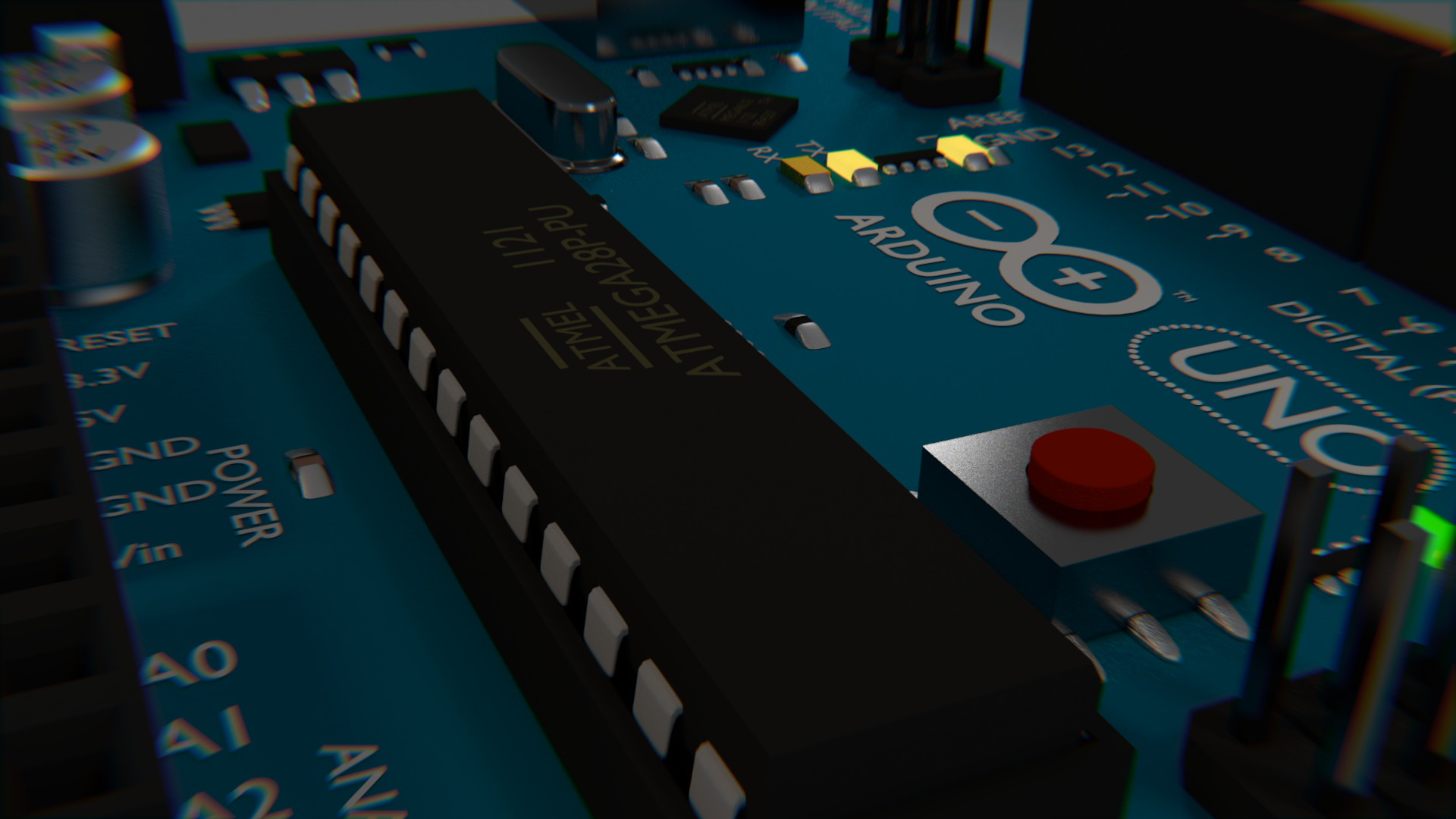
Results
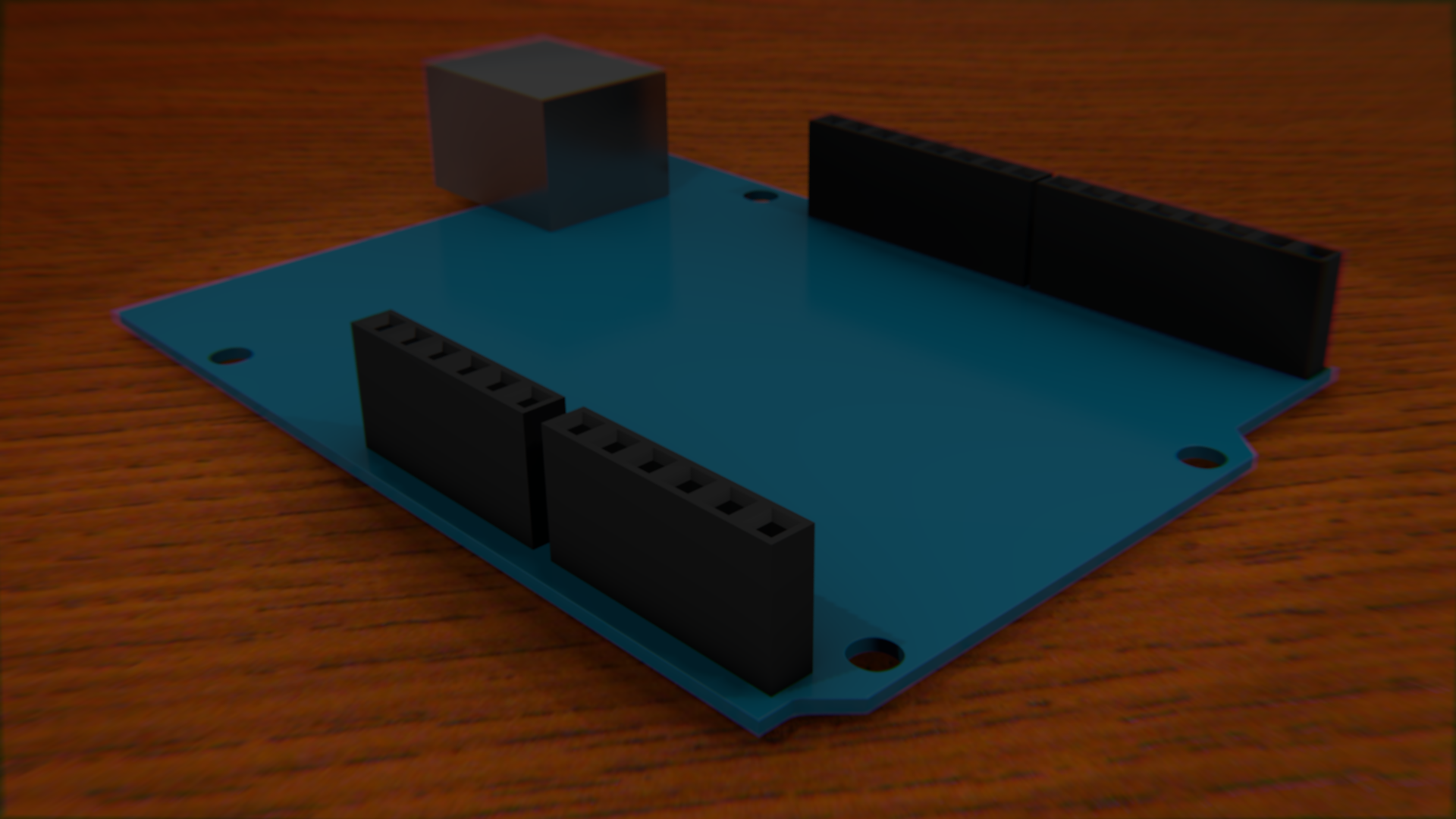
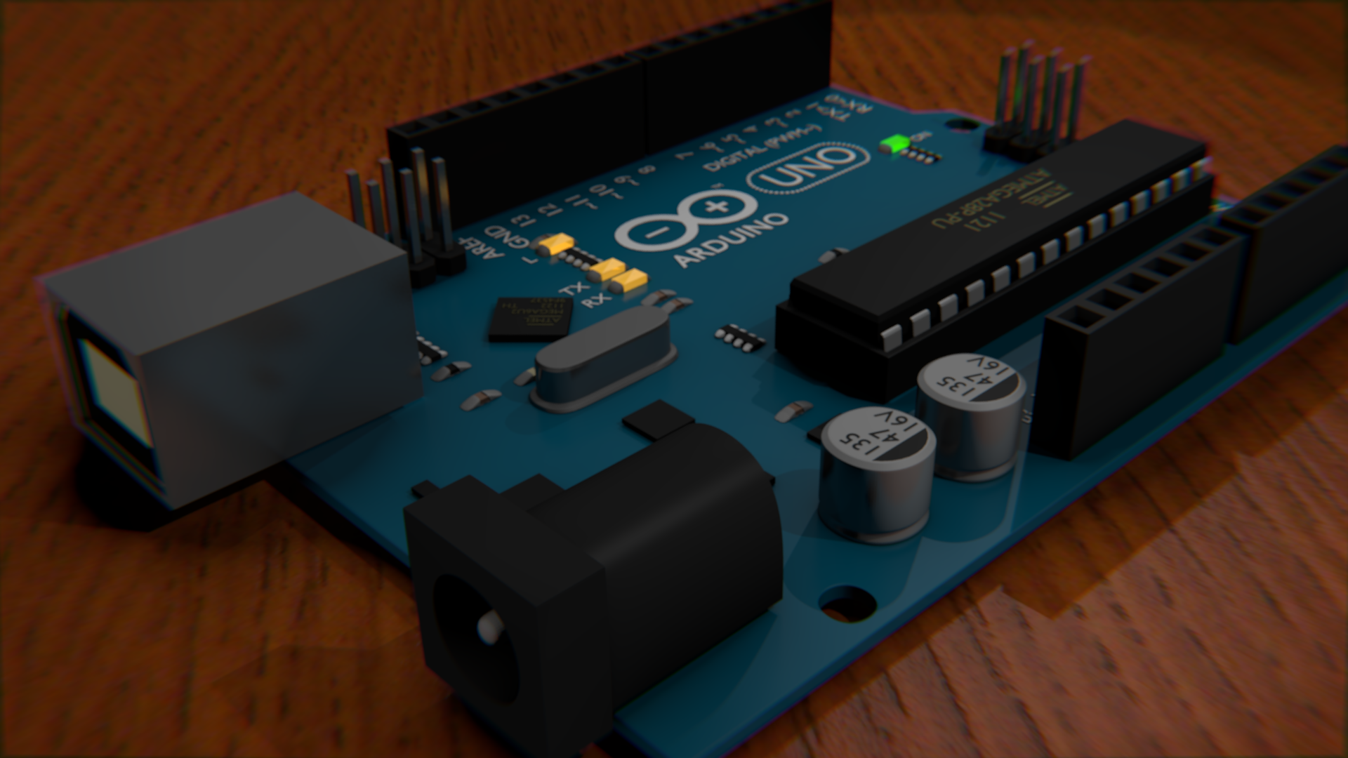
I could not really find any great Blender models of the Arduino Uno on the internet, so I decided to make my own. Mine was made entirely from scratch and does not use any image textures (except the wood in this demo). It features most of the details of the Uno, but does not have the printed circuitry. It was modelled off an image and some eyeballing for sizes, so it may not necessarily be to scale, but it looks close enough for Blender work. Even the text is there, using the default Blender font. The Arduino logo is actually a mesh of a circle. The most notable chips have the proper text on them, and the plugs even are shaped like sockets.

See the bottom of this post for the .blend files, or read more to see how it was done.
Progress
I kept renders from each of the steps along the way. I will describe each set of renders with a paragraph for each render in line from left to right.
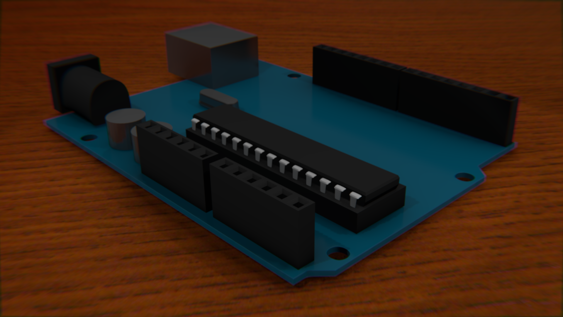
So, I start by tracing the board from an image, which was actually easy. Then "loop cut and slide" was done several times to square off the holes. Once the square holes are made, the subdivision modifier is applied. The edges on the top and bottom of the squares must be hardent with shift+e, otherwise it will look more like a worn down area than a drilled hole. The USB connection was easy. Picking the right material for it was the important part. It should be reflective and still have some roughness to it. Just one pin was made, then an array was used to duplicate the pin in a row. Then different sets were made by Shift+D for duplicate.
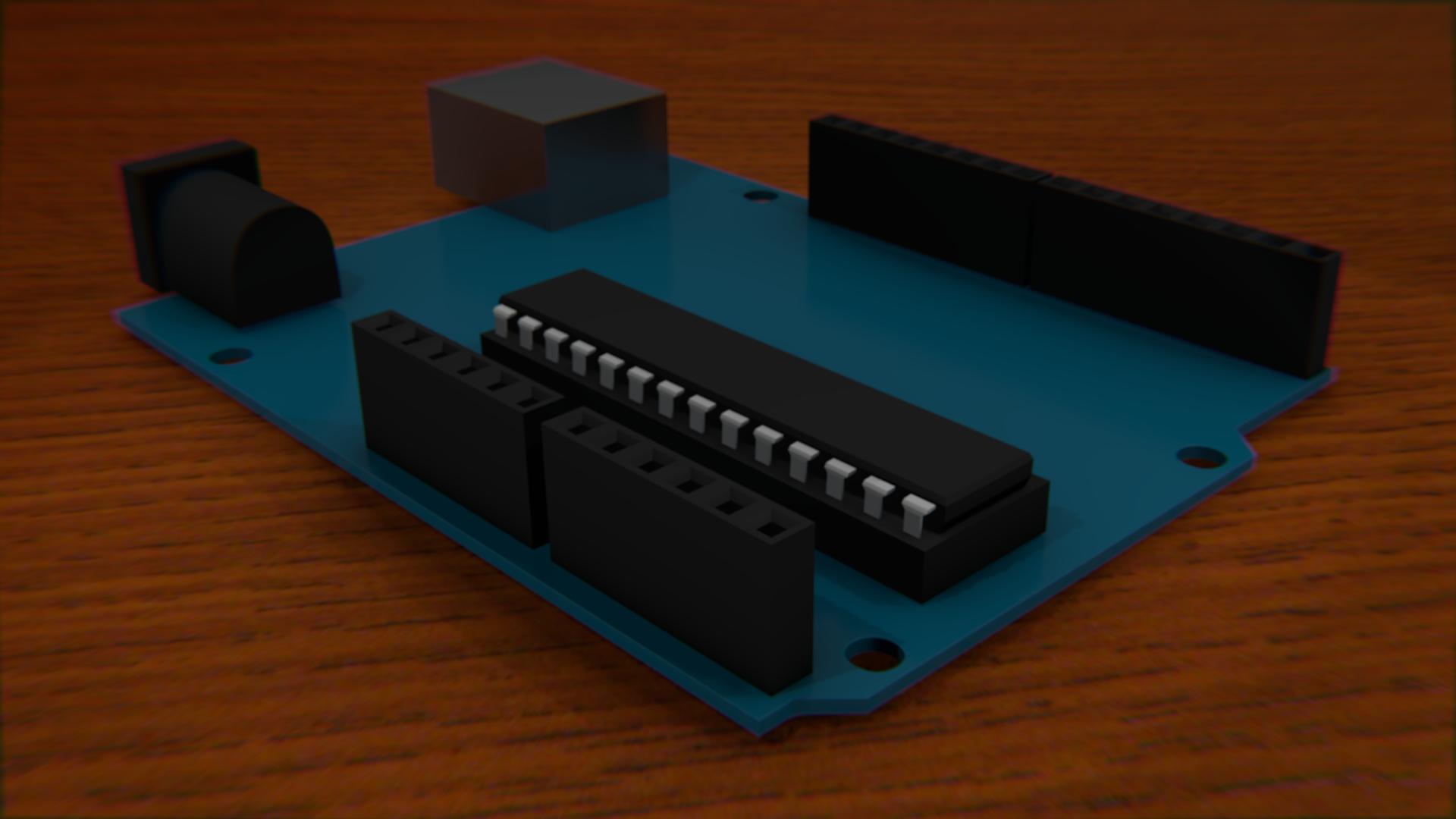
The power socket was easy, with just a cube. Extrude one face twice - once bigger then another the same size. Then subdivisions are applied to give the back end the rounded look. All edges but the top back two should be at their hardest with shift + e. The ATMEGA is actually really easy to do except for the pins, which never quite seem to look right.
I started trying to add the capacitors and the piezo by using cylenders, but that was the wrong way to go about it. Subdivisions are a lot easier.
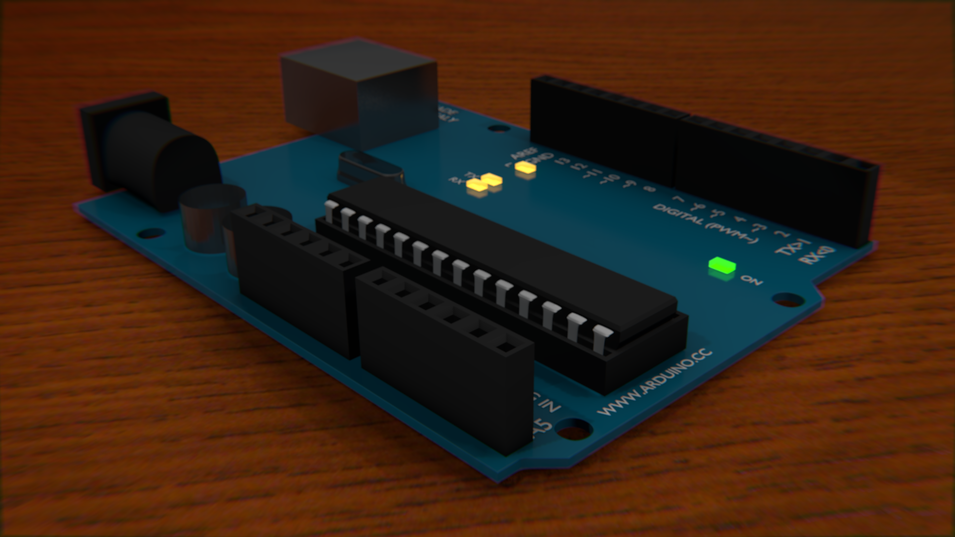
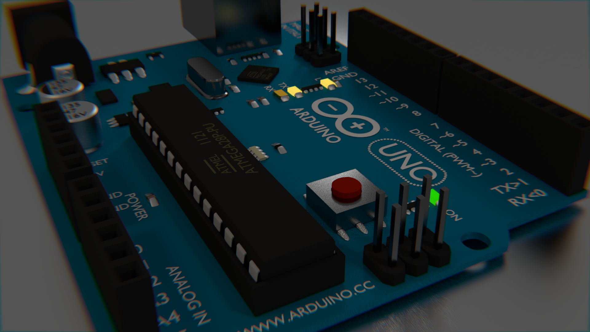
I realized that adding the text was going to be really important to making it look right. It was actually easy enough to add it in exactly the right places due to the use of a "background image" on the camera. When in wireframe mode, you can see both the text and the image you are tracing. The font is clearly wrong when looking at the comparison image, but it is not so obviously wrong when just looking at these images. The biggest difference is that the I is supposed to have the caps on it. The LEDs were added and turned on, just because they could be. It was later pointed out that it would be impossible for an arduino to have both on at the same time.
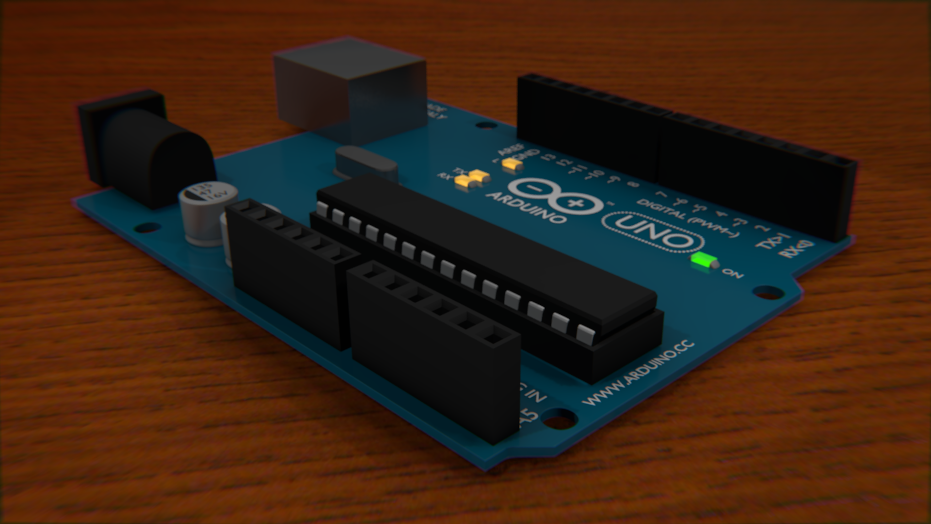
The arduino logo is simply a circle mesh extruded inward, then deformed a little bit. Here, I also fixed the capacitor and piezo to use subdivisions, and added the accurate notches and protrusions to each. I really like the way the black text on the capacitors looks. Again, the black side is just a circle.
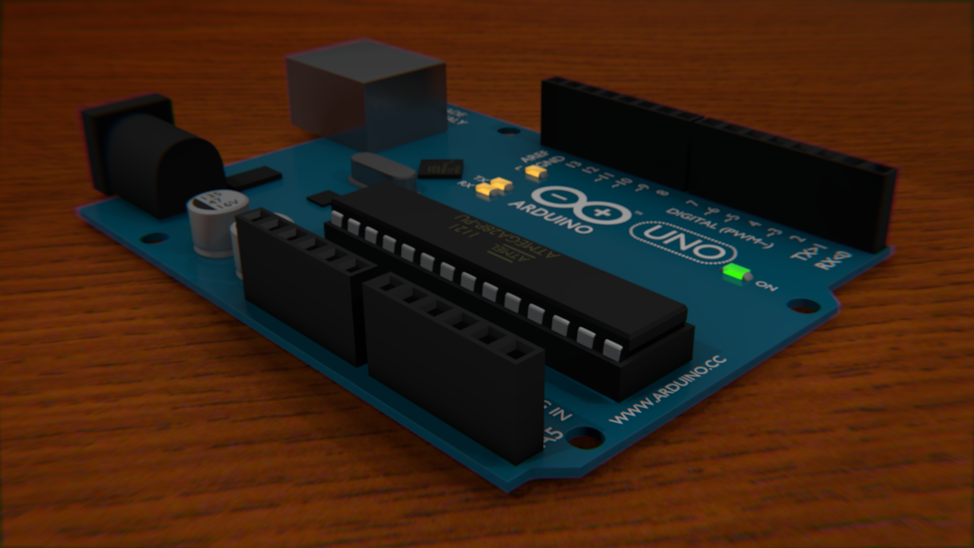


Of course the Arduino needs the text on the ATMEGA chip!. I also added some black boxes for the smaller chips that are scattered on the board. Here, a couple more black chips are being added to the board.
Here, I added the sockets to the USB and Power blocks. They did not have the interior parts before, but you couldn't see that. I still don't really like the way the interior of the USB socket looks, but I didn't really care as much about that feature.
I also wanted to add all of the little resistors and tiny components that litter the board, but decided to test how just this one works before duplicating it. I also tweaked the matte plastic texture a bit by making its specular less intense.
I then duplicated the resistors all over the place wherever they were needed. The pins that... well, actually I don't know what those ones that protrude do - I have never used them. Anyway, they were easy enough to make I didn't even use an array. I just duplicated them.
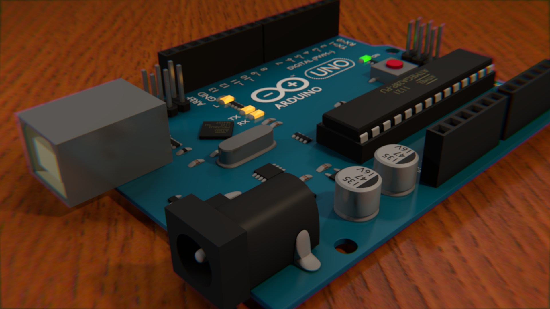
And of course, the reset button had to be added. That was just a box with a subdivided box on top. I also added connecting solder to a bunch of components. It's supposed to be mildly reflective, since it uses the same material as the capacitors, but it never really shows in these demos - probably because there is no skymap.
Cycles Tests
Cycles is a next-generation rendering engine in Blender. It is completely different than the current renderer, so the materials and textures system is entirely different and doesn't transfer back and forth. In theory, it is superior due to the fact that it all light bounces off things onto others. For example, if you have a light in your home that points upward toward the ceiling - as long as the ceiling is a light color it will still light the rest of the room since the light bounces off the ceiling too. The default blender render does not do this by default - but can be made to with the indirect lighting feature.
I struggled with the environment lighting in Cycles. The world material made a huge change in the overall lighting, and no matter what I tried nothing seemed to look quite right. However, the components themselves tended to have much better looks in cycles. I also decided to switch to a glossy demo surface just because It sort of looks nice with it's reflectivity. In some ways, these renders look nicer, and in some ways they look way worse.
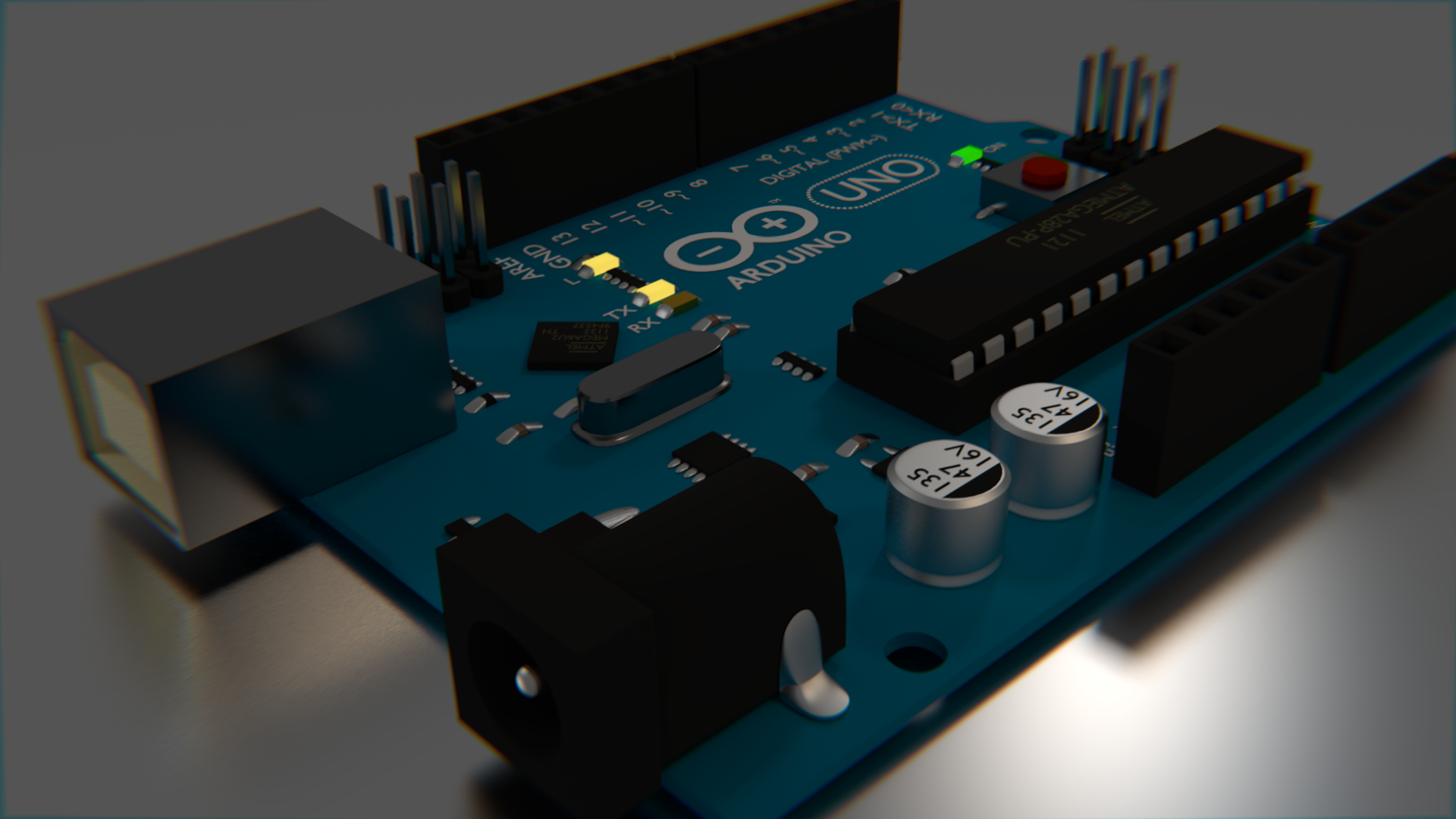


Really, converting it to cycles was as simple as just enabling "use nodes" on all the materials and then changing it to glossy in most cases. Very little tweaking was needed with the exception of the LEDs, which needed to be emission types, but they didn't look quite right when they were just emitting, so I mixed an emission type with a regular one so that it was looked a little more in place.
I sort of wish that the LED's looked better than they do. They glow, but they don't really light up their surroundings as much as I would like, which is made extremely obvious by the dim environment lighting I settled with in cycles.
LCD - Sainsmart HD44780 / LCD2004
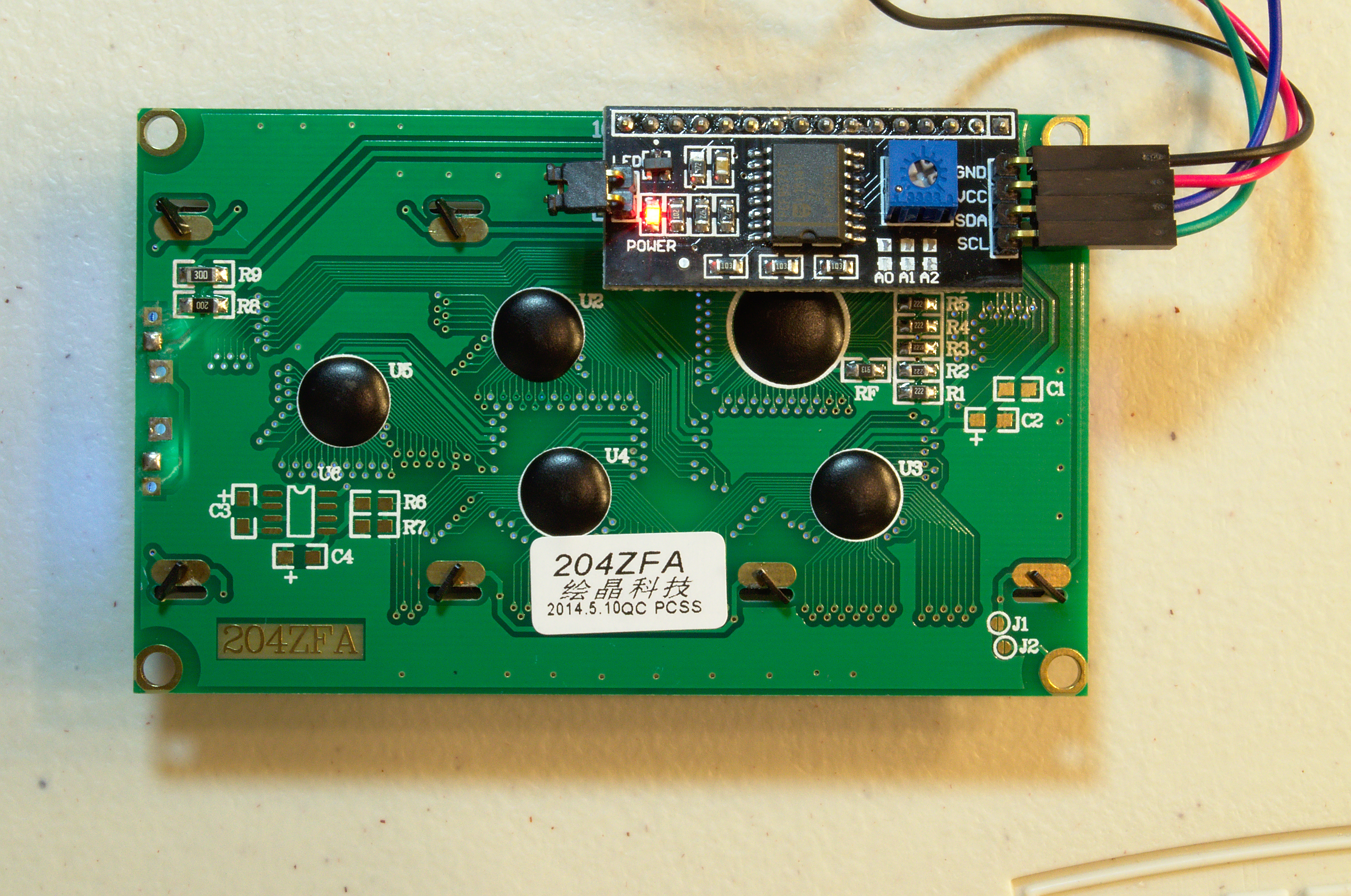
LCD - Sainsmart HD44780 / LCD2004Introduction
This is a very simple LCD display that has a two wire serial interface. It displays characters, not pixels. It can show 20 characters in a row and 4 rows. They are fairly inexpensive at retail - only about $10. They have a toggleable backlight and a variable contrast.

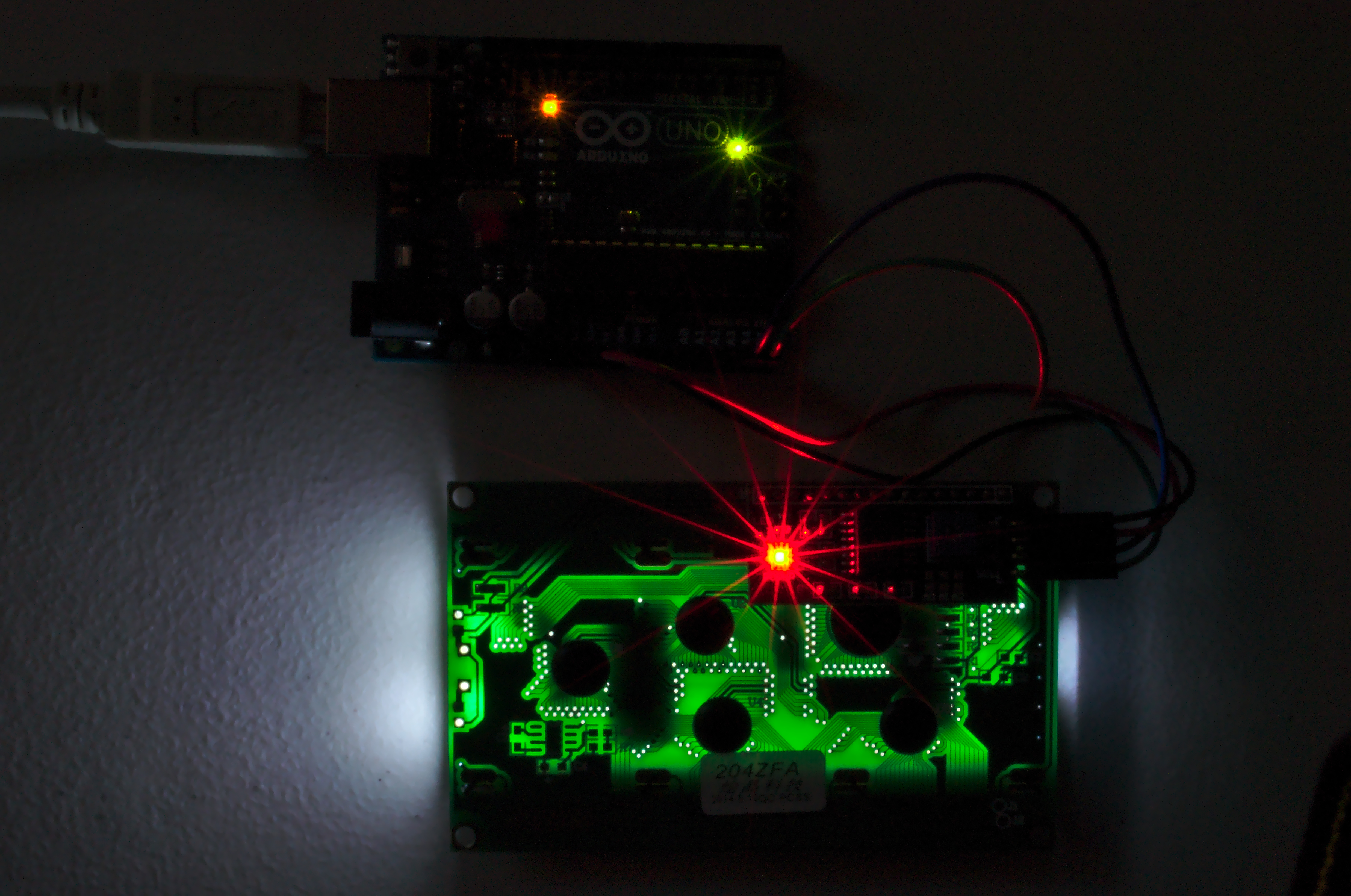
Wiring
The serial controller (or backpack) takes 5V, so connect the 5V and GND to the 5V and GND on the Arduino. The SDA and SCL pins are trickier. Depending on your Arduino, it could go any number of places, as seen in the table at the right.
| Board | SDA | SCL |
| Uno | A4 | A5 |
| Mega2560 | 20 | 21 |
| Leonardo | 2 | 3 |
| Due | 20 | 21 |
The most common board is the Uno, and the wiring of it can be seen here. Where SDA is the blue wire and SCL is the green wire - as is convention.
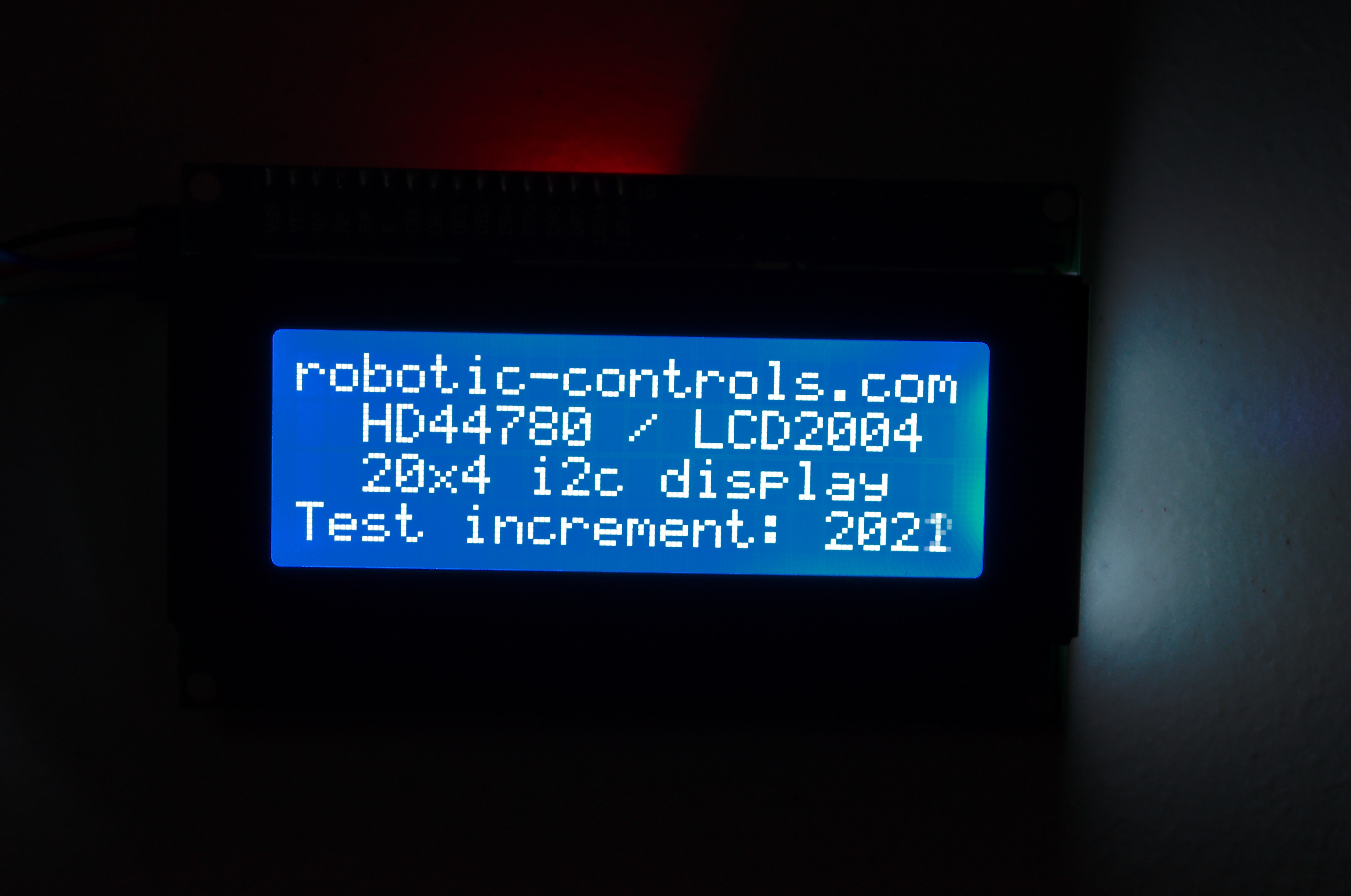
Coding
This code displays the information shown in the pictures above. It requires that you have some libraries installed. I have attached the version I used for convenience and preservation. However, the library is originally available from here, and a more up-to-date version may be available there.
The library must be installed in your Arduino folder. The folder location is:
| Windows | %HOMEPATH%/My Documents/Arduino/ibraries/ |
| OS X | ~/Documents/Arduino/libraries/ |
| Linux | ~/Documents/Arduino/libraries/ |
Download the LiquidCrystal library .zip folder and extract the whole folder into the libraries folder for your system above.
#include <Wire.h>
#include <LiquidCrystal_I2C.h>

#define I2C_ADDR    0x27  // Define I2C Address where the PCF8574A is
                          // Address can be changed by soldering A0, A1, or A2
                          // Default is 0x27

// map the pin configuration of LCD backpack for the LiquidCristal class
#define BACKLIGHT_PIN 3
#define En_pin  2
#define Rw_pin  1
#define Rs_pin  0
#define D4_pin  4
#define D5_pin  5
#define D6_pin  6
#define D7_pin  7

LiquidCrystal_I2C lcd(I2C_ADDR,
                      En_pin,Rw_pin,Rs_pin,D4_pin,D5_pin,D6_pin,D7_pin,
                      BACKLIGHT_PIN, POSITIVE);

void setup() {
  lcd.begin(20,4);        // 20 columns by 4 rows on display

  lcd.setBacklight(HIGH); // Turn on backlight, LOW for off

  lcd.setCursor ( 0, 0 );            // go to the top left corner
  lcd.print("robotic-controls.com"); // write this string on the top row
  lcd.setCursor ( 0, 1 );            // go to the 2nd row
  lcd.print("  HD44780 / LCD2004 "); // pad string with spaces for centering
  lcd.setCursor ( 0, 2 );            // go to the third row
  lcd.print("  20x4 i2c display  "); // pad with spaces for centering
  lcd.setCursor ( 0, 3 );            // go to the fourth row
  lcd.print("Test increment: ");
}

int n = 1; // a global variable to track number of display refreshes

void loop() {
  lcd.setCursor (16,3);         // go to col 16 of the last row
  lcd.print(n++,DEC);           // update the display with a new number
                                // - overwrites previous characters
                                // - be sure new number is more digits
  delay(500);                   // wait half a second before another update
}